540HP NA 7L V12 3 seater
Discussion


On the F1, or indeed any car with such a roof air scoop, any idea how they also prevent water entering the inlets?
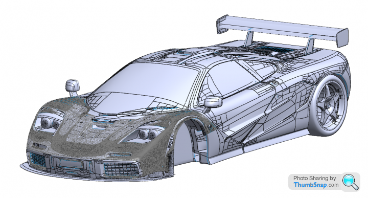
Got myself a central seat/ 3 seater project at last, the plan originally was an F1 LM clone but now decided to make it a one off design with the F1 and T50 as inspiration instead.
Got myself a central seat/ 3 seater project at last, the plan originally was an F1 LM clone but now decided to make it a one off design with the F1 and T50 as inspiration instead.
PAUL.S. said:
On the F1, or indeed any car with such a roof air scoop, any idea how they also prevent water entering the inlets?
Got myself a central seat/ 3 seater project at last, the plan originally was an F1 LM clone but now decided to make it a one off design with the F1 and T50 as inspiration instead.
According to Murray:Got myself a central seat/ 3 seater project at last, the plan originally was an F1 LM clone but now decided to make it a one off design with the F1 and T50 as inspiration instead.
Murray said:
We had to design a water separator, trap and drain to avoid filling the engine with water when following a truck in the rain
From https://www.roadandtrack.com/car-culture/car-desig... in turn quoting a Car interview.Sorry, no idea how to successfully design a reliable water separator, trap and drain in a tight space. Perhaps an expired patent search? I remember reading that the airflow over the windscreen separates the air naturally due to the scoops position, but can't remember source of that info, might be in windtunnel section of DA.
I didn't want to spend time developing something that might let me down in the worst weather conditions so thought best solution is to avoid it altogether. Main concern is dealing with heavy deluges and icy conditions, which in both cases will require a gentle throttle and therefore engine performance will not suffer having the cold air intake shut off almost completely.
Nice article link, my vote is for the NSX.
Edited by F1natic on Tuesday 5th September 12:28
F1natic said:
Sorry, no idea how to successfully design a reliable water separator, trap and drain in a tight space. Perhaps an expired patent search? I remember reading that the airflow over the windscreen separates the air naturally due to the scoops position, but can't remember source of that info, might be in windtunnel section of DA.
I didn't want to spend time developing something that might let me down in the worst weather conditions so thought best solution is to avoid it altogether. Main concern is dealing with heavy deluges and icy conditions, which in both cases will require a gentle throttle and therefore engine performance will not suffer having the cold air intake shut off almost completely.
Nice article link, my vote is for the NSX.
Pragmatic choice.I didn't want to spend time developing something that might let me down in the worst weather conditions so thought best solution is to avoid it altogether. Main concern is dealing with heavy deluges and icy conditions, which in both cases will require a gentle throttle and therefore engine performance will not suffer having the cold air intake shut off almost completely.
Nice article link, my vote is for the NSX.
Edited by F1natic on Tuesday 5th September 12:28
A bit more insight here: https://www.quora.com/How-do-hood-scoops-keep-out-...
marine boy said:
It's been a few years ago but I'm sure the original McLaren F1 used VW Corrado mirrors, yours look very similar
I had moulds taken off a VW part and then designed lightweight carbon mirror bodies with an extend plinth for the 97 long-tail car
Other parts raided from parts bins that I can remember are push button door locks were from the boot of an Audi 80 cabriolet, Lotus Elan front indicators, Citroën AX interior lights and for a one off cigarette lighter/ash tray upgrade from a Merecedes SL500.
Rear lights I think we're Hella units commonly used on German HGV trailers commonly
One of your creations? I had moulds taken off a VW part and then designed lightweight carbon mirror bodies with an extend plinth for the 97 long-tail car
Other parts raided from parts bins that I can remember are push button door locks were from the boot of an Audi 80 cabriolet, Lotus Elan front indicators, Citroën AX interior lights and for a one off cigarette lighter/ash tray upgrade from a Merecedes SL500.
Rear lights I think we're Hella units commonly used on German HGV trailers commonly

https://www.racecarsdirect.com/Advert/Details/1395...
Continue a bit of the last discussion, found this -->
https://www.thelotuscentreonline.co.uk/epages/sdct...
A brand new lens, housing, and gasket for cheaper than most want for some beat up lenses.
Tried to place the order online but unfortunately the system wouldn't complete the transaction citing something with shipping. I sent them an email so hopefully it's just due to it being an international order.
Bumping for an update.
As an aside, those turn indicators came in and are perfect.
BTW, if you want, I have a -nice- model of an F1 LM; also have the 3D scan info from an actual F1 GTR (Dark gray). (Also have 3D scan info for the rear fascia).
As an aside, those turn indicators came in and are perfect.
BTW, if you want, I have a -nice- model of an F1 LM; also have the 3D scan info from an actual F1 GTR (Dark gray). (Also have 3D scan info for the rear fascia).
Edited by RandomTask007 on Wednesday 18th October 20:26
CedricN said:
For a couple of quid there are rubber one way valves which are used in the bottom of ait boxes to drain out water and not let air by.
I think that would only work with pooled water, the engine would be sucking in the air and water before it had time to sit at the bottom. The odd thing is that cars can use water injection to cool them and I can’t see a lot of rain being an issue….obviously Gordon Murray thought it was and as such I would trust him more.RandomTask007 said:
Bumping for an update.
As an aside, those turn indicators came in and are perfect.
BTW, if you want, I have a -nice- model of an F1 LM; also have the 3D scan info from an actual F1 GTR (Dark gray). (Also have 3D scan info for the rear fascia).
Unfortunately my project has languished in the background as work/hobby balance is currently skewed in the wrong direction, although the door hinges are almost finalised for printing and casting. The timing of your offer to share a genuine GTR scan is absolutely perfect, especially if it has door detail. Very much appreciated, drop me a DM. As an aside, those turn indicators came in and are perfect.
BTW, if you want, I have a -nice- model of an F1 LM; also have the 3D scan info from an actual F1 GTR (Dark gray). (Also have 3D scan info for the rear fascia).
Have also been spending a bit of my spare time assessing subsurface modelling as a way of generating highly organic machinable surfaces, something I find difficult to control precisely in Solidworks - this video shows the technique I am working through;
https://www.youtube.com/watch?v=3rlMzsBWtPY
Congrats on collecting quite the array of genuine parts, it is really nice to have tactile objects to help drive the enthusiasm for your project.
Caddyshack said:
I think that would only work with pooled water, the engine would be sucking in the air and water before it had time to sit at the bottom. The odd thing is that cars can use water injection to cool them and I can’t see a lot of rain being an issue….obviously Gordon Murray thought it was and as such I would trust him more.
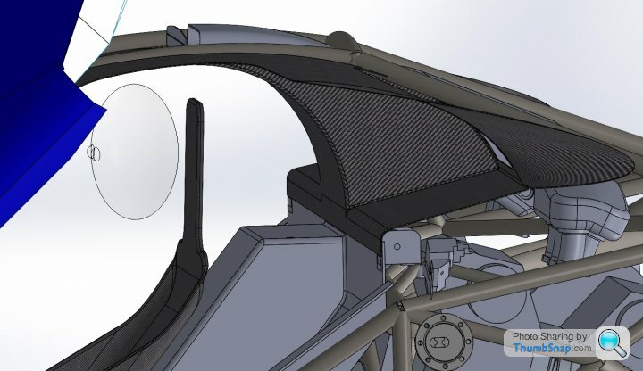
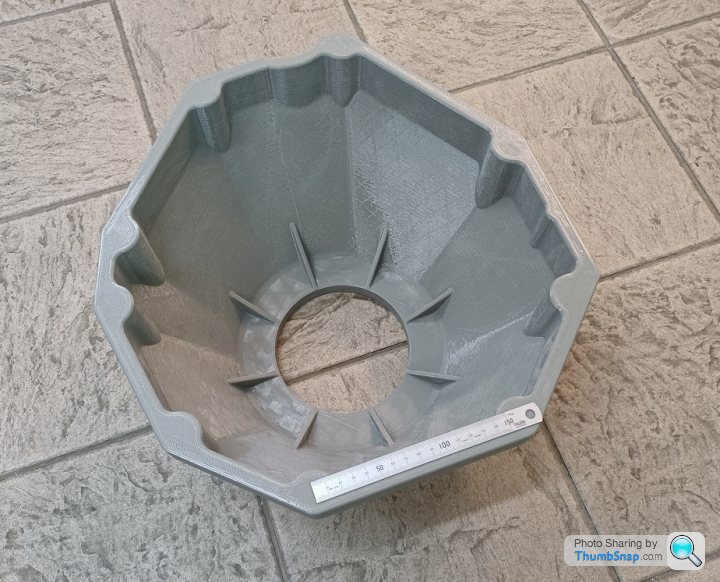
The F1 has 2 big conical air filters under the panel ahead of the plenum chamber, so depending on the air velocity profile water could coalesce and drain by gravity (out of any duckbills) before entering the plenum. Just like driving a convertible in the rain as long as you have forward movement a certain degree of filtering of heavy elements is achieved by the nature of the airstream over the scoop, plus a certain amount of water will be tolerated by a hot engine. However my problem is the massive steel rollover structure right where the filters would reside, so had to run the scoop through a smaller gap, with water separation at the front and filters nearer the rear. Some of the design is contingency planning, I probably won't end up building it unless it is actually required - the scoop deflector is probably one of them. The donor car was taken for it's last drive today, as I need the axles from it for my daily driver. After a proper warmup captured a range of ballpark datapoints for setting up the speeduino on the test engine, wideband O2 will be used to refine the fueling table.
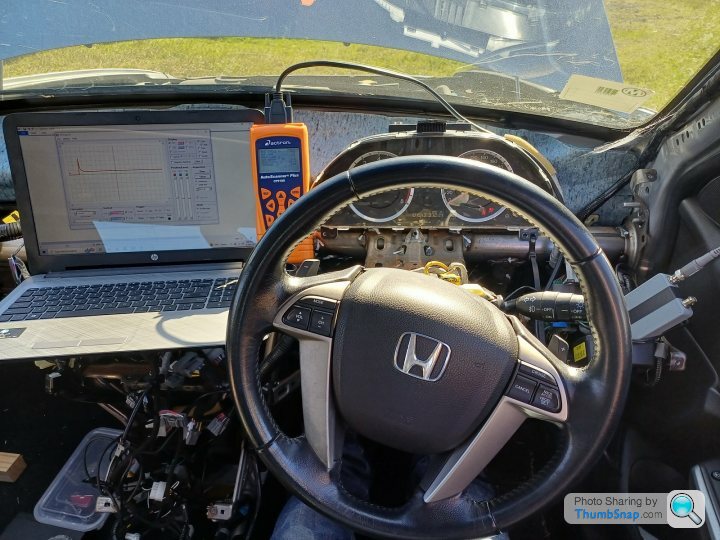
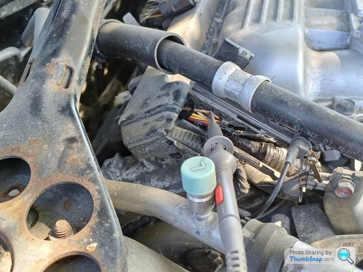
Sliced into the ignition signal wire to get a contact for the oscilloscope probe. Coil on plug dwell is 2.5ms at idle, around 3ms at higher loads.

The ECU grounds the injector coil so intercepted the wiring on the injector coil ground side to analyse the injector pulsewidth across a range of engine loads. Car in drive and brakes fully on, holding throttle at the desired MAP values that the speeduino will use as the engine load axis. Transmission oil got very hot but as it's off the road now not an issue.
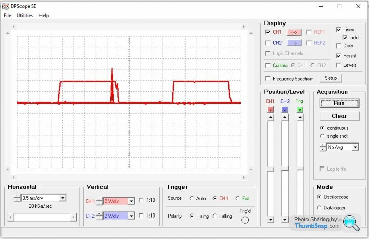
DPscope capture of full throttle injector pulsewidth - leads are set to 1:10 so voltage captured properly, however not sure they were correctly attenuated, but was really only interested in the pulsewidth anyway.
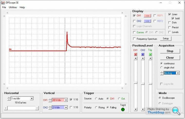
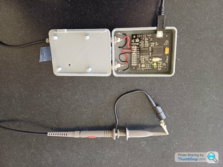
The laptop is running the DPscope software, works good enough for my budget/purposes. 16 quid plus shipping.
https://www.picaxestore.com/catalogsearch/result/?...
3D printed a housing and soldered leads to the 2 BNC connectors.
Sliced into the ignition signal wire to get a contact for the oscilloscope probe. Coil on plug dwell is 2.5ms at idle, around 3ms at higher loads.
The ECU grounds the injector coil so intercepted the wiring on the injector coil ground side to analyse the injector pulsewidth across a range of engine loads. Car in drive and brakes fully on, holding throttle at the desired MAP values that the speeduino will use as the engine load axis. Transmission oil got very hot but as it's off the road now not an issue.
DPscope capture of full throttle injector pulsewidth - leads are set to 1:10 so voltage captured properly, however not sure they were correctly attenuated, but was really only interested in the pulsewidth anyway.
The laptop is running the DPscope software, works good enough for my budget/purposes. 16 quid plus shipping.
https://www.picaxestore.com/catalogsearch/result/?...
3D printed a housing and soldered leads to the 2 BNC connectors.
Edited by F1natic on Sunday 12th November 08:03

The original position does not suit the Mercedes SLK door latches being used for this build, however with a bit of "adapting" (using a grinder to remove the superfluous material from the OEM parts) and swapping around the installation can achieve something functionally very close.

The component on the left is a standard right hand door assembly, where the mechanism would be mounted inside the door. Dihedral doors typically have the latch mechanism in the body and the striker pin on the door, so in this case taking a cutdown LH mechanism (shown on the right) and rotating it so the striker approaches from the topside works - at least in the CAD assembly.

Countless hours have been spent trying to resolve the clearance around and mounting of the modified door latches to the frame, happy now with the solution that ties the passenger seat belt retractor mount into the door latch mounting plate and a major chassis node.
The component on the left is a standard right hand door assembly, where the mechanism would be mounted inside the door. Dihedral doors typically have the latch mechanism in the body and the striker pin on the door, so in this case taking a cutdown LH mechanism (shown on the right) and rotating it so the striker approaches from the topside works - at least in the CAD assembly.
Countless hours have been spent trying to resolve the clearance around and mounting of the modified door latches to the frame, happy now with the solution that ties the passenger seat belt retractor mount into the door latch mounting plate and a major chassis node.
Edited by F1natic on Friday 24th November 23:21
Indeed "DA" is such a good source of photos from behind the scenes of the F1's creation. The chaps at IDAT did a great job too, although have never seen any photos of their work as I expect they were under confidentiality agreements. The whole process of taking the approved plug and reverse engineering the body panel tooling from it would have been a huge and highly skilled undertaking - modern scanning and CNC accessibility has likely replaced some of these skills? Would really like to hear how the process is currently done by someone involved in this aspect of the trade.
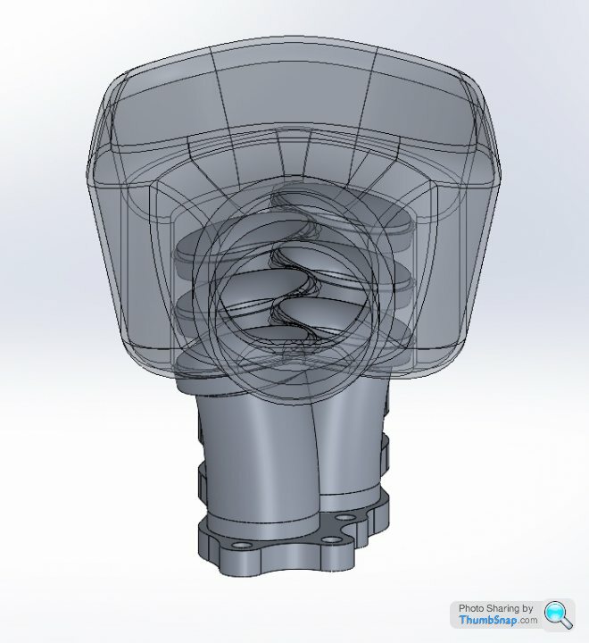
Next casting off the rank is a test bellhousing - hopefully for use on the secondary motor as no bosses or cutouts for the starter were detailed as I have run out of 2023. Will be cast in aluminium grade A356.
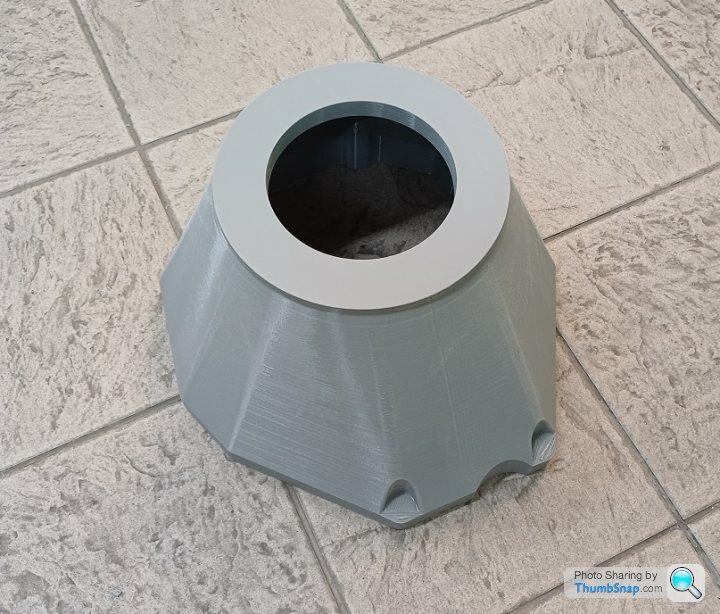
Next casting off the rank is a test bellhousing - hopefully for use on the secondary motor as no bosses or cutouts for the starter were detailed as I have run out of 2023. Will be cast in aluminium grade A356.
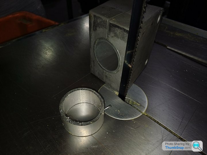
A while ago I 3D printed then cast in 4140 a small press tool for the intake tubes, finally got around to testing it. Worked out well as a cutting off guide in the bandsaw too. One dozen inlets took about an hour to make.

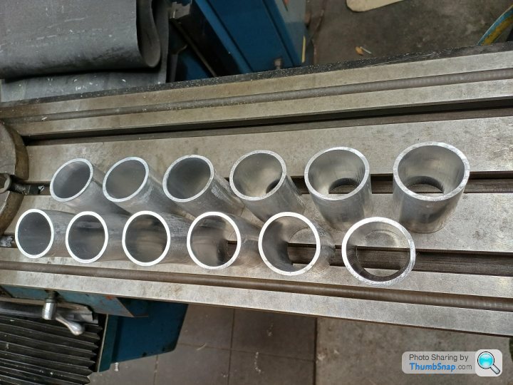
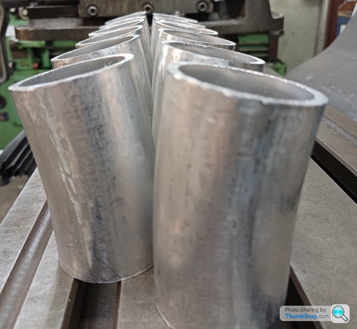
Will need to turn up some bellmouths and weld them to these tubes, then weld the tubes to the CNC'd lower plate which then bolts onto the standard honda lower intake manifold
Will need to turn up some bellmouths and weld them to these tubes, then weld the tubes to the CNC'd lower plate which then bolts onto the standard honda lower intake manifold
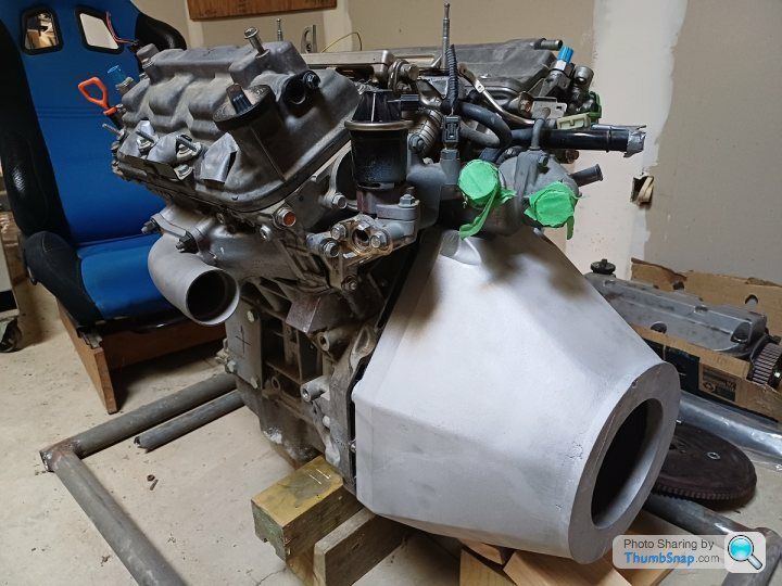
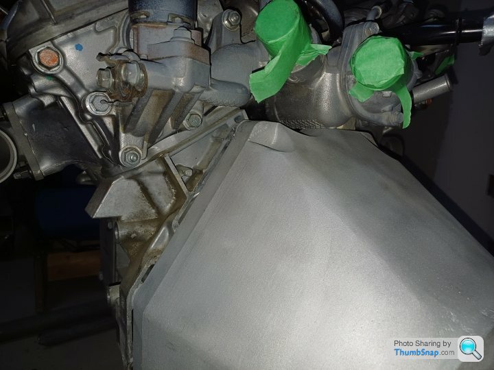
Bellhousing casting came out well for the first attempt;
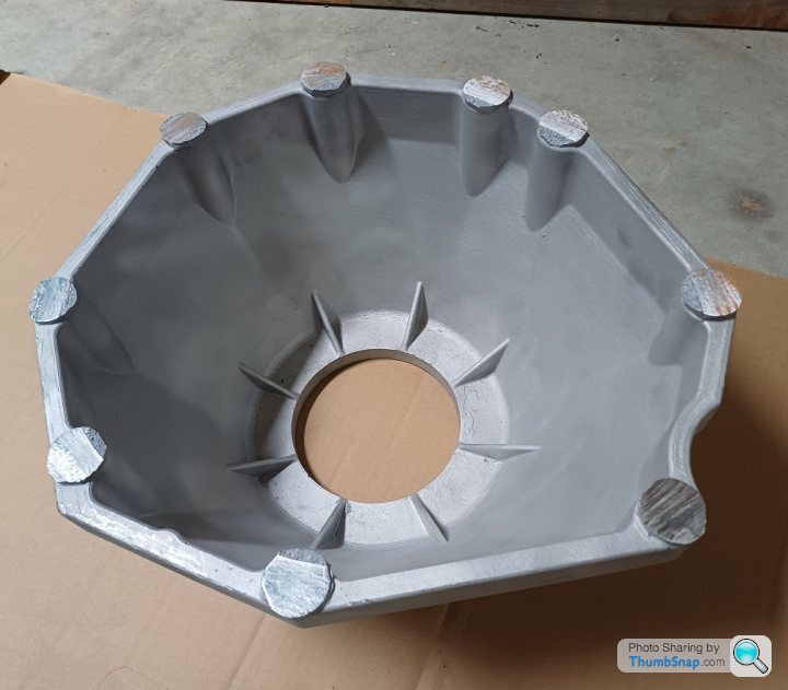
Fit looks good so will proceed to heat treat and machining in the new year - there was generous machining allowance included at each end.
Also knocked off a small task of blocking off the auxiliary line in the corvette fuel pump with a small brass pin - now it needs a tank to be fitted into!


Fit looks good so will proceed to heat treat and machining in the new year - there was generous machining allowance included at each end.
Also knocked off a small task of blocking off the auxiliary line in the corvette fuel pump with a small brass pin - now it needs a tank to be fitted into!
Edited by F1natic on Monday 18th December 06:57
Gassing Station | Readers' Cars | Top of Page | What's New | My Stuff