Effect of a 38mm restrictor on an LS7
Discussion


Firstly, appologies for not following this thread up before now, as i have been having some internet issues (mainly getting shafted by my ISP it turns out ;-(
Anyways,
1) you want the MAF before the restrictor generally (although it will work perfectly well downstream, you will find that it's diameter (which is generally fixed) will not be optimum for fitting into your new inlet system.
2) The ems will probably work fine with the restrictor, as the fuelling side is MAF + LAMBDA, and the ignition is MAP. However, you may find the transient fuelling a bit odd, and possibly get some transient detonation as well, as the throttle angle / vs plenum pressure relationship will have been modified by the restrictor. I'm guess you race on premium fuels, so det issues are unlikely, as the stock ecu will have a safe spark advance limit on "fruity blends"
3) You need to get the air flowing through the restrictor to be as laminar and columnar as possible. You need the hydraulic diameter to be as close as possible to the physical diameter of the restrictor choke. This means no tight bends in front, and ideally a large volume immediately upstream of the restrictor, with a large suitably designed bellmouth leading into the critical choke. The aim is to get the highest stagnation pressure possible upstream of the restrictor, and to present the most even velocity distribution to the inlet face. You can use the forward velocity of the vehicle to raise the stagnation pressure above ambient if the system is designed correctly.
4) The design of the intake bellmouth is almost as critical as the exit nozzle, but a lot lot harder to get right. As mentioned ^^^ a simple laminar expansion nozzle (with suitably low included cone angle) will get you a very good discharge co-efficient. But on the inlet side, the exact shape of the bellmouth is critical to maintaining an even total pressure (static pressure is traded smoothly for dynamic pressure). Not only do you have to get a smooth velocity profile, but ideally also a smooth acceleration of that velocity into the critical choke. (much like designing decent cam profiles actually ;-) (something Racingpuma might just about be good at by now............ ;-) (right back at ya!)
5) check the regs very carefully for positioning and total system volume requirements, some transient performanc benefit can be gained by introducing a large enough volume downstream of the critical choke etc.
The plan is that my navigator, who owns an aluminium fabrication shop, will do a CAD design to my/forum derived spec and then get a chap over the road to CNC machine it. It is, however, handy to have a back up plan!
I shall spend today working out how I can keep the inlet and outlet of the restrictor straight whilst turning 180 deg from the inlet manifold to air filter box.
I shall spend today working out how I can keep the inlet and outlet of the restrictor straight whilst turning 180 deg from the inlet manifold to air filter box.
The engine is in the back and the inlet manifold reversed bringing the air inlet into the car. There is a double skinned roof allowing cold,reasonably clean, air intake.
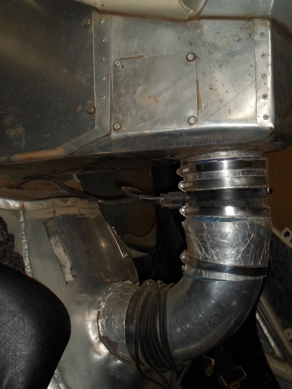
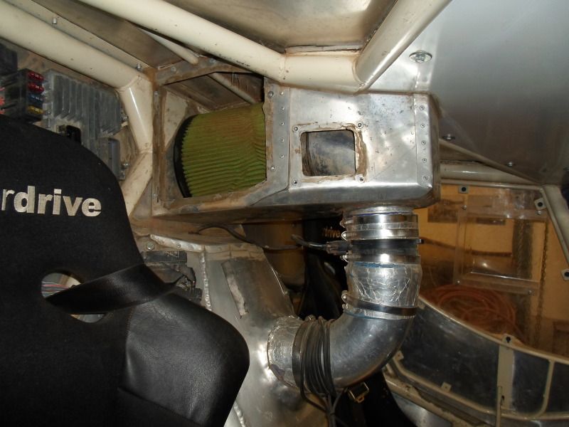
The centre line of the filter and throttle body are 350mm apart. I could move the MAF into the airbox which would give me @180mm for a restrictor where the MAF is. But, there would be 90 deg bends either side.
The centre line of the filter and throttle body are 350mm apart. I could move the MAF into the airbox which would give me @180mm for a restrictor where the MAF is. But, there would be 90 deg bends either side.
It would make fitment easier.
Ringram, you may recall a couple of years ago you kindly came up and changed the way my rev limiter works. It's much better now.
Will I need to change some settings in the ECU if I remove it? You picked up I most likely had a couple of wires off the MAF with your computer, which was correct. It seemed to run fine apart from a momentary hesitation at @ mid throttle.
An update for you.
I have just done a race with a restrictor. It was done at short notice, the French firstly decided to postpone introduction until next year and then a week before the event changed their minds. They've also reduced it to 37.2mm.
Further to the advice on here, and with off forum help from Ringram, I removed the MAF and fitted a separate intake temp probe. Because of the short notice I ran with a simple bellmouth restriction and no exit cone.
It ran a bit flat and obviously wouldn't rev out. However the standard GM ECU soon adjusted itself and performance wasn't as bad as I was expecting. The engine management light didn't come on.
So, I now have until next April to sort out a more efficient arrangement.
Thanks to those who contributed, no doubt I'll be back with some more questions.
Hi Racing-Friends,
I'm writing because I'm searching for an expert in using engines with turbo and air restrictor. I'm racing a car with 38mm air restrictor which must be placed 30cm in front of the compression wheel in a 2.0 TFSI from Volkswagen.
Right now the power is somewhere around 360hp an torque is about 460Nm. I have to upgrade to about 550Nm.
I got everything around the engine ready, except the turbo and the compression rate. Maybe you can help me with my last questions:
1. I have to use a turbo with K04 body. Might it be better to use bigger turbine and/or compression wheel?
2. Right now the enginge has a compression ratio of 9.8:1 Might it be better to reduce the compression to somewhere around 9.3:1 to use higher boost? I have to use 100 Octan gaz.
Edited by GolfR1974 on Sunday 3rd February 13:37
Steve_D said:
C Lee Farquar said:
......However the standard GM ECU soon adjusted itself and performance wasn't as bad as I was expecting........
It will have managed this using Long term fuel trim which will be lost if you power down the ECU so you need to be aware of that.Steve
But I imagine the VE table could be well out of whack with the restrictor, so could well do with a revamp.
This may be a case of where the long term trims to help.
Powering down the ECU, which is done each time I turn off the ignition, seemed to make no difference to the mapping. I didn't argue the point because as I don't hack the ECU so it's anecdotal. However I did manage to root my phone and flash the ROM this weekend so maybe I get brave with the ECU 
To update the thread, I ordered and have just received a Raetech restrictor. The quality is top notch and looks like it just wants to flow air. I'm moving the air cleaner to optimise the positioning. I'm hoping to race in April but the car is currently in component form.
To update the thread, I ordered and have just received a Raetech restrictor. The quality is top notch and looks like it just wants to flow air. I'm moving the air cleaner to optimise the positioning. I'm hoping to race in April but the car is currently in component form.
C Lee Farquar said:
Powering down the ECU, which is done each time I turn off the ignition, seemed to make no difference to the mapping......
The ECU should have both ignition switched supplies to it and permanent supplies so unless you have yours wired differently then the permanent supply will maintain the ECU trims when the ignition is off.Steve
Regulation change for this year, restrictor size up to 42mm and 15 litres of air allowed between the throttle and restrictor. From 37.2mm this about 30% bigger area, and I believe a bigger percentage increase in flow?
I'd bought one of the Raetech restrictors pictured above at 37mm. There isn't enough meat on this to bore out so I have a local machinist scaling it up. I'm redoing the whole intake to take advantage of the 15 litres and to incorporate a better air cleaner. Separate thread on the air cleaner.
I'd bought one of the Raetech restrictors pictured above at 37mm. There isn't enough meat on this to bore out so I have a local machinist scaling it up. I'm redoing the whole intake to take advantage of the 15 litres and to incorporate a better air cleaner. Separate thread on the air cleaner.
I thought I'd update this thread.
The engine has been using a fair amount of oil, about a gallon for 120km of competition, 200km of liaison.
Last event it started running rough on the last day
Earlier in the year, 5.45 into video
Near the end, 36.44 and 41.49 into the video
My car sounds lazy compared to the others as most run five/six speed sequential boxes, I have a three speed auto TH350.
The oil light had come on about four times on a stage the previous night, I had underestimated the consumption.
To me it sounded like it was missing the next day.
It stopped as I crossed the line at the end of the final stage.
Engine is now out
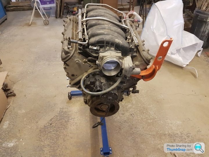
Initial inspection shows one big end has spun and bore wear is up to about 6 thou.
Plan is to take the block in for machining early Jan, I'm hoping a rebore can be done at 10 thou.
There seems to be quite a bit of disparity of opinion as to how much the LS7 can be bored out, 10 thou pistons are readily available, anything bigger is thinner on the ground. I believe this is due to the liner thickness.
A new crank is just over £500, which would be OK. A new block is about £2500 which would be painful.
I've never had the OEM GM ECU tuned for the restrictor, but plan to do so if it will rebuild.
Some oil was being pulled through the air intake from the crank case. I'm sure the bore wear would be from a few years back when I had an ineffective air cleaner.
I'm not convinced the engine sounding rough was related to the big end spinning and would welcome opinions.
The engine has been using a fair amount of oil, about a gallon for 120km of competition, 200km of liaison.
Last event it started running rough on the last day
Earlier in the year, 5.45 into video
Near the end, 36.44 and 41.49 into the video
My car sounds lazy compared to the others as most run five/six speed sequential boxes, I have a three speed auto TH350.
The oil light had come on about four times on a stage the previous night, I had underestimated the consumption.
To me it sounded like it was missing the next day.
It stopped as I crossed the line at the end of the final stage.
Engine is now out
Initial inspection shows one big end has spun and bore wear is up to about 6 thou.
Plan is to take the block in for machining early Jan, I'm hoping a rebore can be done at 10 thou.
There seems to be quite a bit of disparity of opinion as to how much the LS7 can be bored out, 10 thou pistons are readily available, anything bigger is thinner on the ground. I believe this is due to the liner thickness.
A new crank is just over £500, which would be OK. A new block is about £2500 which would be painful.
I've never had the OEM GM ECU tuned for the restrictor, but plan to do so if it will rebuild.
Some oil was being pulled through the air intake from the crank case. I'm sure the bore wear would be from a few years back when I had an ineffective air cleaner.
I'm not convinced the engine sounding rough was related to the big end spinning and would welcome opinions.
Commented just to follow.
Max_torque you blow my mind. I swear I am a reasonably intelligent guy, all be it in electronics not engine design but I literally have no clue what your saying sometimes (no offence intended, your clearly an expert in your field). I'm now off to read about air flow and intake design so I can understand it.
Don't suppose you have a link to some appropriate reading for a novice trying to follow this. It would be greatly appreciated.
Gassing Station | Engines & Drivetrain | Top of Page | What's New | My Stuff