Hitari Turbo King - Toy grade to Hobby grade conversion
Discussion


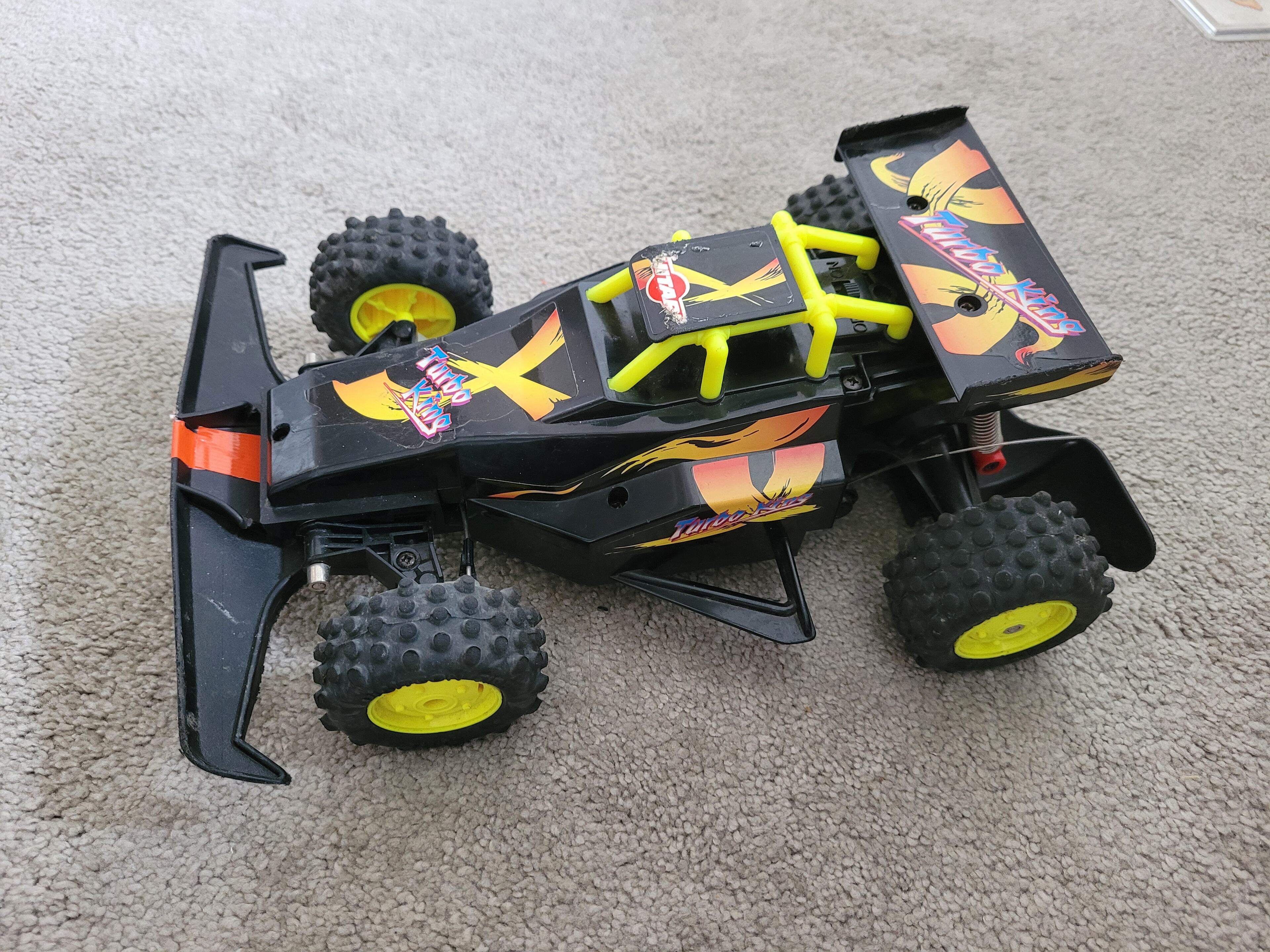
I though some of you might be interested in the little project I have done over the last few weeks, it started when I won a Hitari Turbo King on ebay to relive my childhood a little.
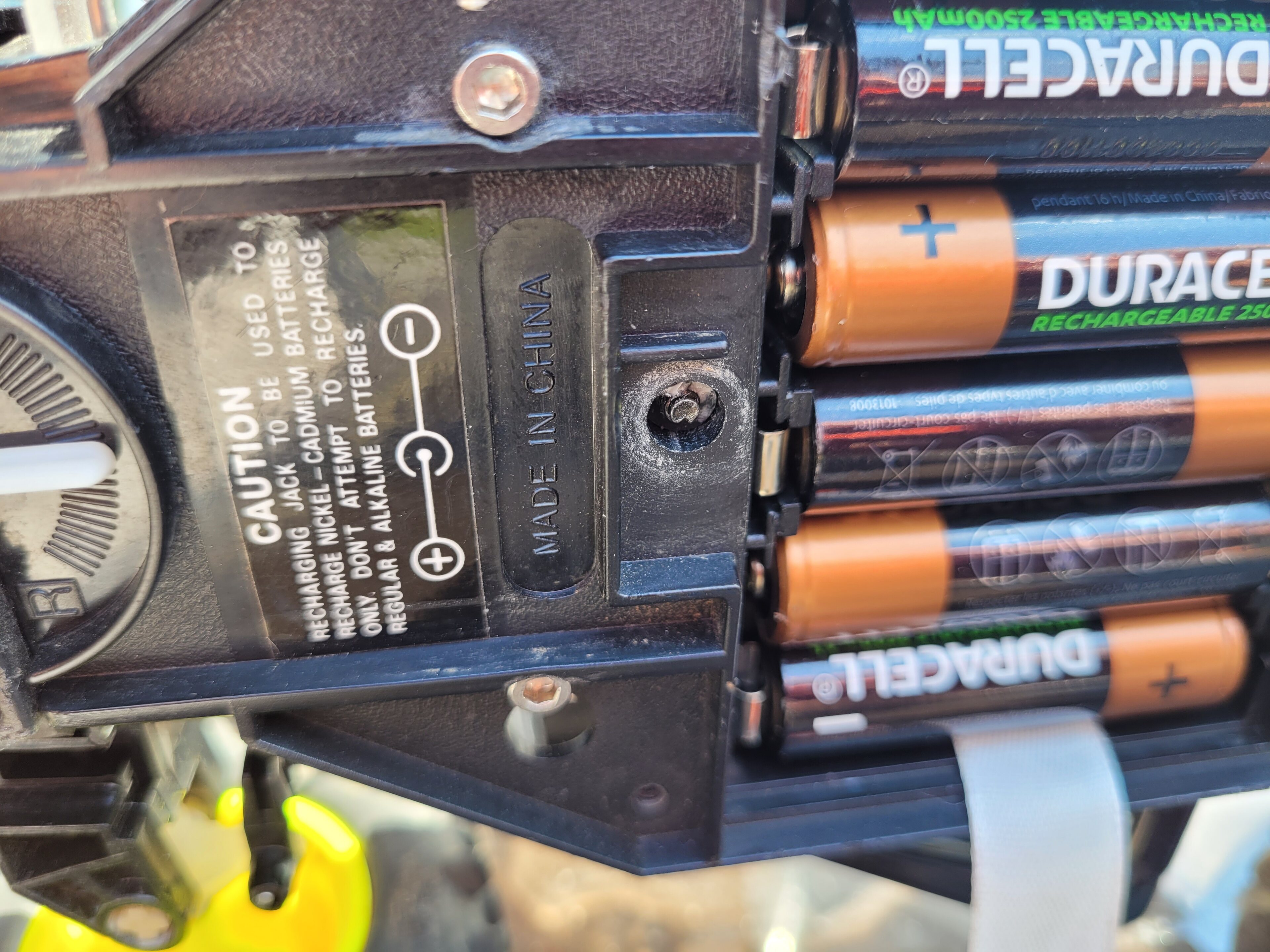
Rather than the Ni-Cd 6V pack that mine had growing up, this one had space for 8xAA batteries, that were then recharged in the car. This meant no concerns over battery degradation as I could fit some modern Ni-MH rechargeable batteries.
Having received the car, and put in 8 fully charged batteries, I was pleasantly surprised by its performance, it was quicker than I remembered! But it was immediately obvious it couldn't output full power and steer at the same time, the motor would cut out when turning. In addition it was a typical toy grade car, so had 2-steps to the speed and the steering was full left or full right only.
Because it was actually relatively fast, I decided it could be fun to upgrade it closer to hobby grade internals, aiming for fully proportional throttle and steering.
I'll follow up with a list of components I used, and then some details of the conversion itself.
For the conversion, I needed a new ESC, Servo and Receiver / Transmitter, for these I aimed to get it cheap, I got them all from AliExpress. Annoyingly with the recent change in tax rules, where the sellers have to add the tax if under £135, this is no longer as cheap as it once was.
Dumbo RC X6 receiver & X6G transmitter. I doubt I'll have any need for the Gyro, but if ever take it out it might be useful in the future,
https://www.aliexpress.com/item/1005004980903440.h...
MG995 Servo - Cheap and metal geared. In hindsight, I should probably have gone with a mini servo as it might have packaged better, but I really liked the aluminium bracket I found, and it did fit neatly in the end
https://www.aliexpress.com/item/1005004841336318.h...
Servo Bracket
https://www.aliexpress.com/item/4000454634346.html...
40A Brushed Speed Controller - I might need to try a different one, as the low voltage cut off is possibly an issue
https://www.aliexpress.com/item/1005004737301865.h...
I then got a Servo Arm, some M3 Tie Rods, M3 bolts, nuts, washers and standoffs of which I have used 2 M3 nuts and bolts. I should have planned the steering conversion in more detail earlier on.
The conversion.
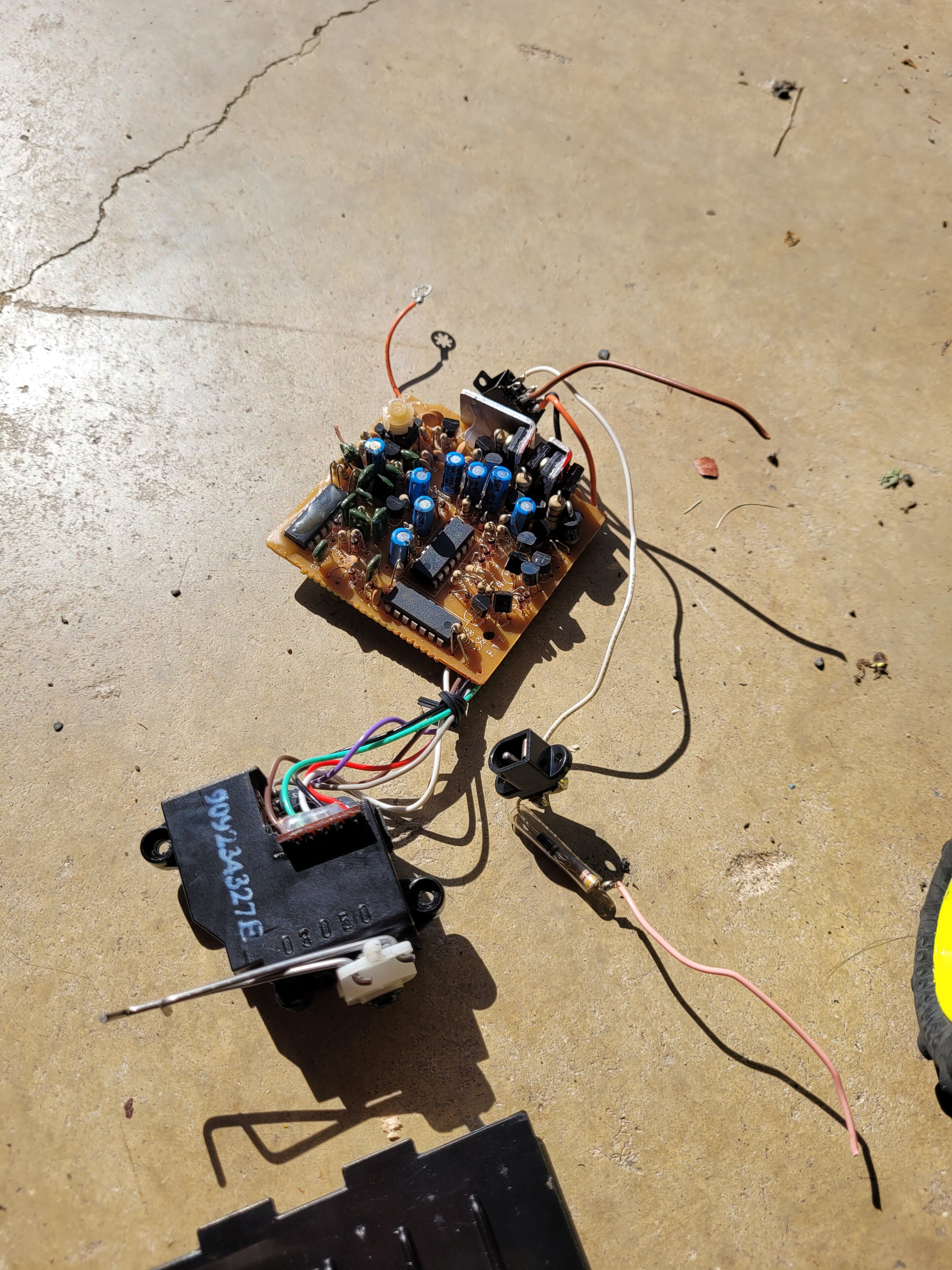
Once all the parts had arrived, I set up to replace all the electronics. First step was to remove the old electronics and steering motor.

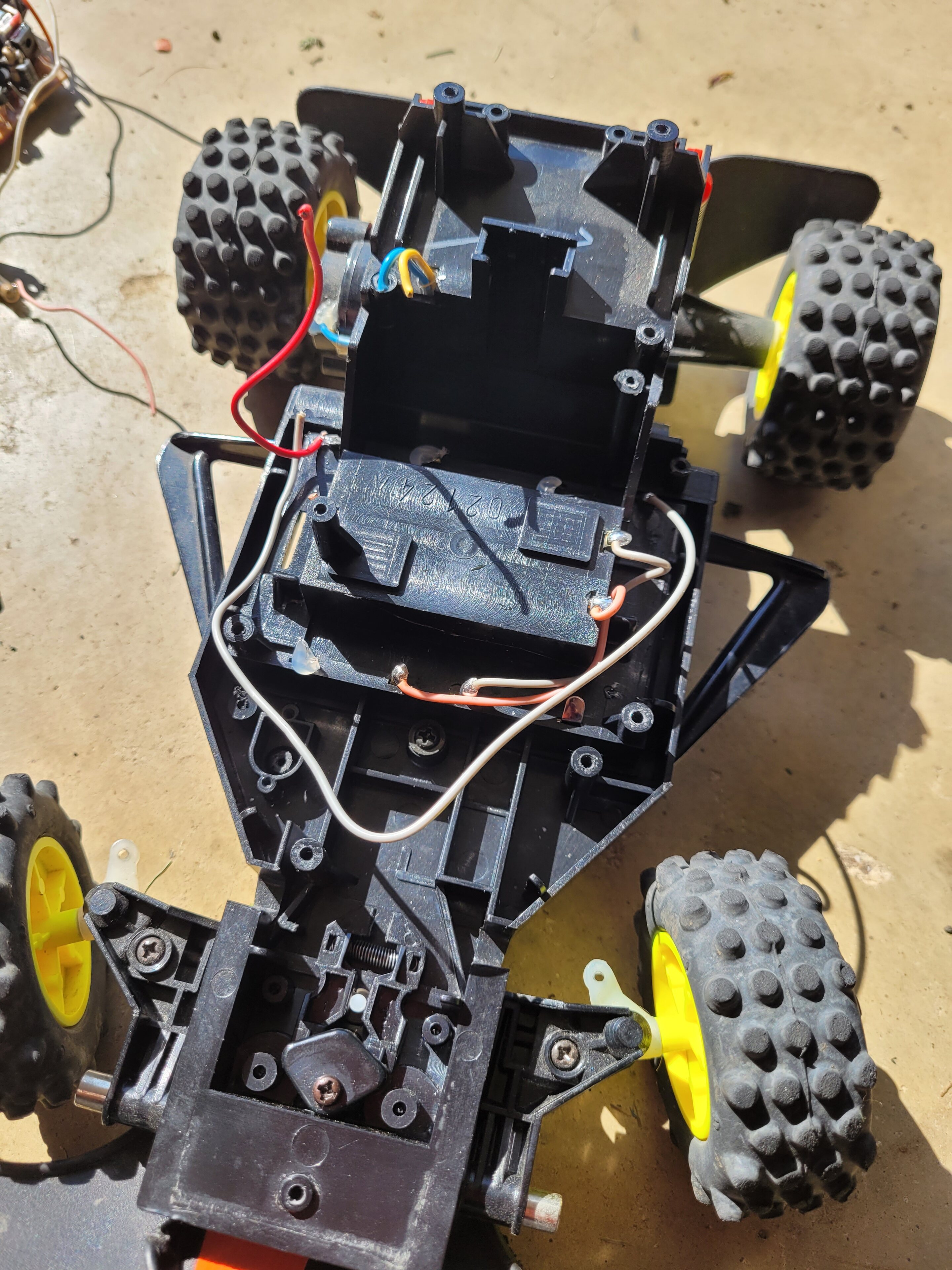
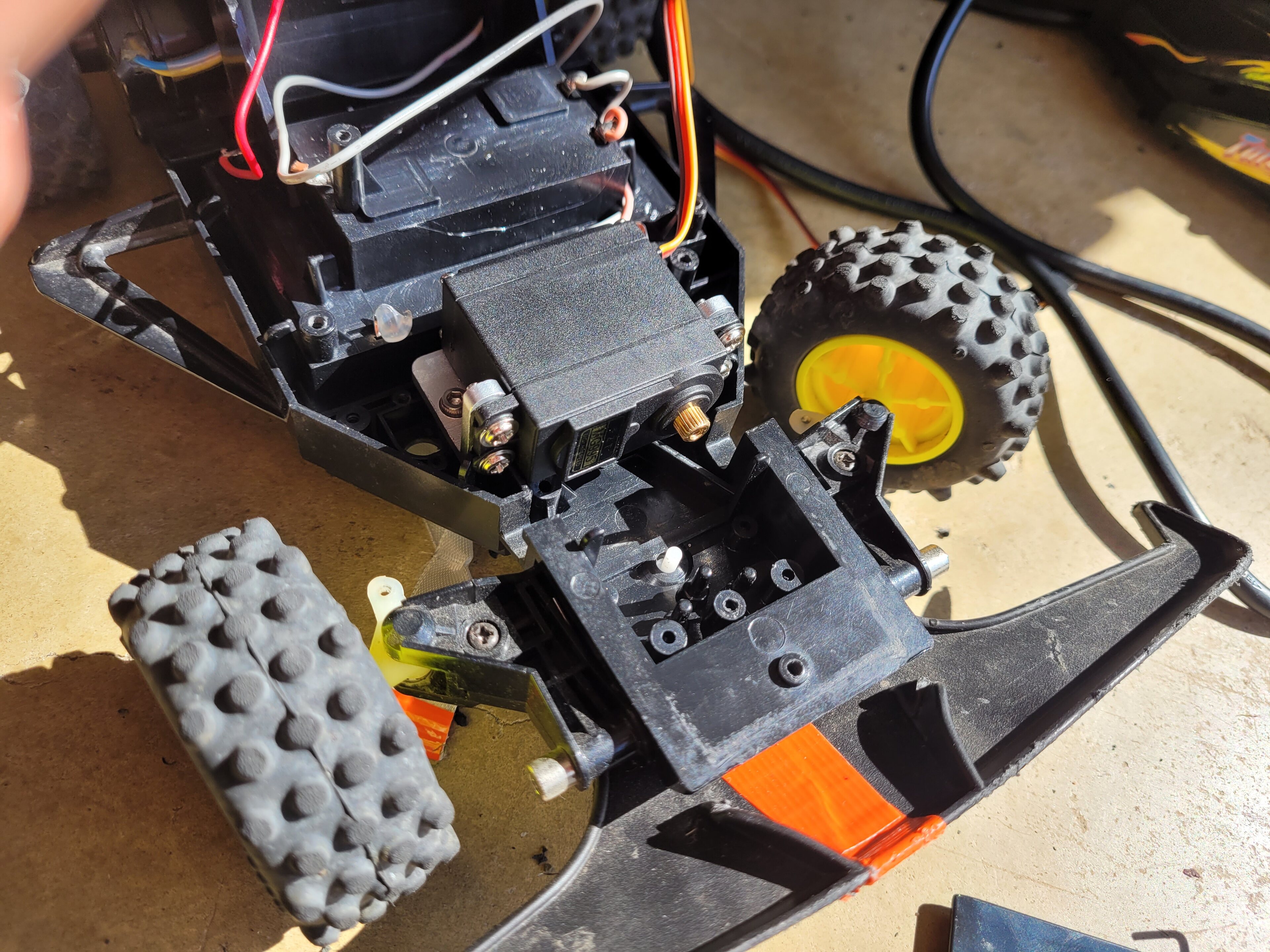
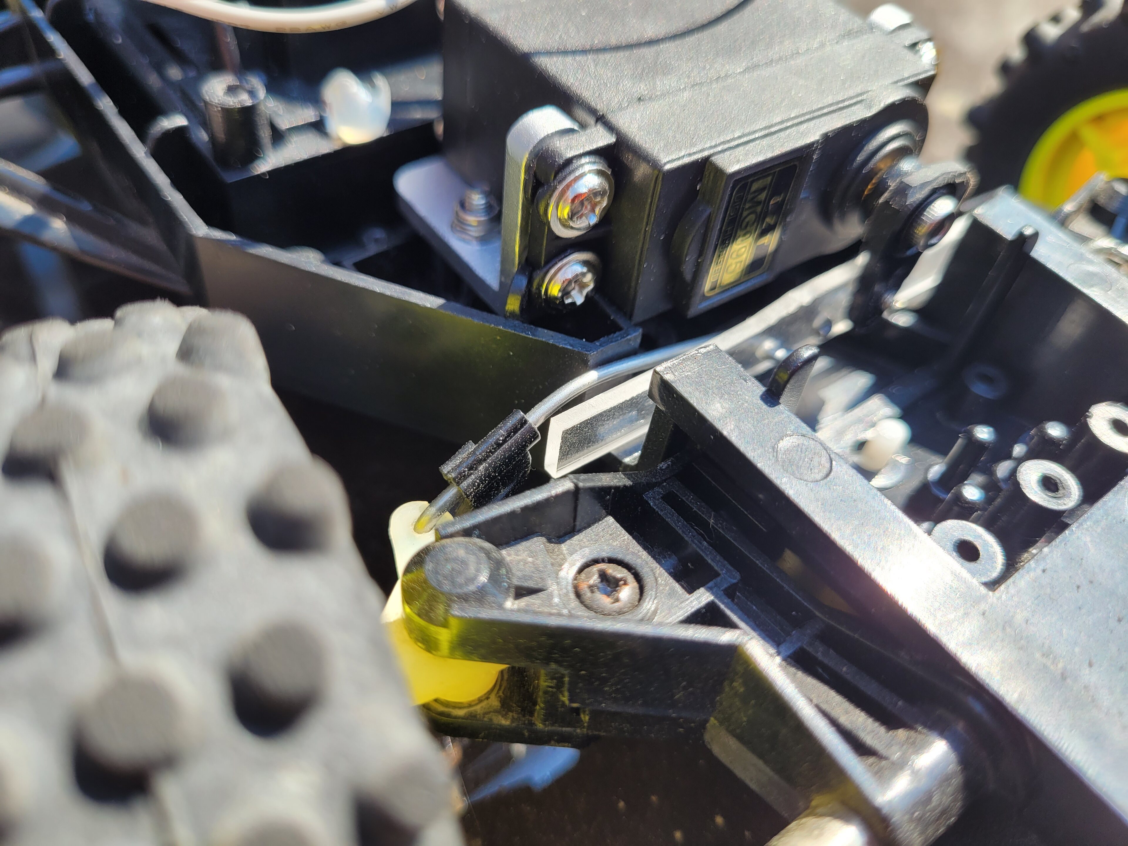
Once I had remove the old internals, I started fitting the new servo and planning new linkages. It turns out I was very fortunate the standard servo fitted in the front of the car, and with the aluminium bracket could be mounted quite easily. I had to trim a little bit of the plastic mounts from the old steering bracket.

As the servo shaft was now off centre, my original plan was to use some M3 adjustable tie rods to the knuckles on each side, but when I started to mock this up, it was quick obvious this wouldn't fit without serious chopping to the original body. Although I am happy to modify it to fit the new internals, I don't want to risk durability to much.
With the tie rods being a no go, I then decided to use the original ~2mm links, with a new bracket. I took a piece of acrylic (because I had some, a less brittle plastic would be better) and mounted the links, as well as one of the plastic servo arms that came with the servo. By keeping the acrylic bracket wider than the chassis, it is prevented from twisting, which helps to keep everything straight despite the offset servo mount, It took 3 acrylic brackets before I was happy with the result.
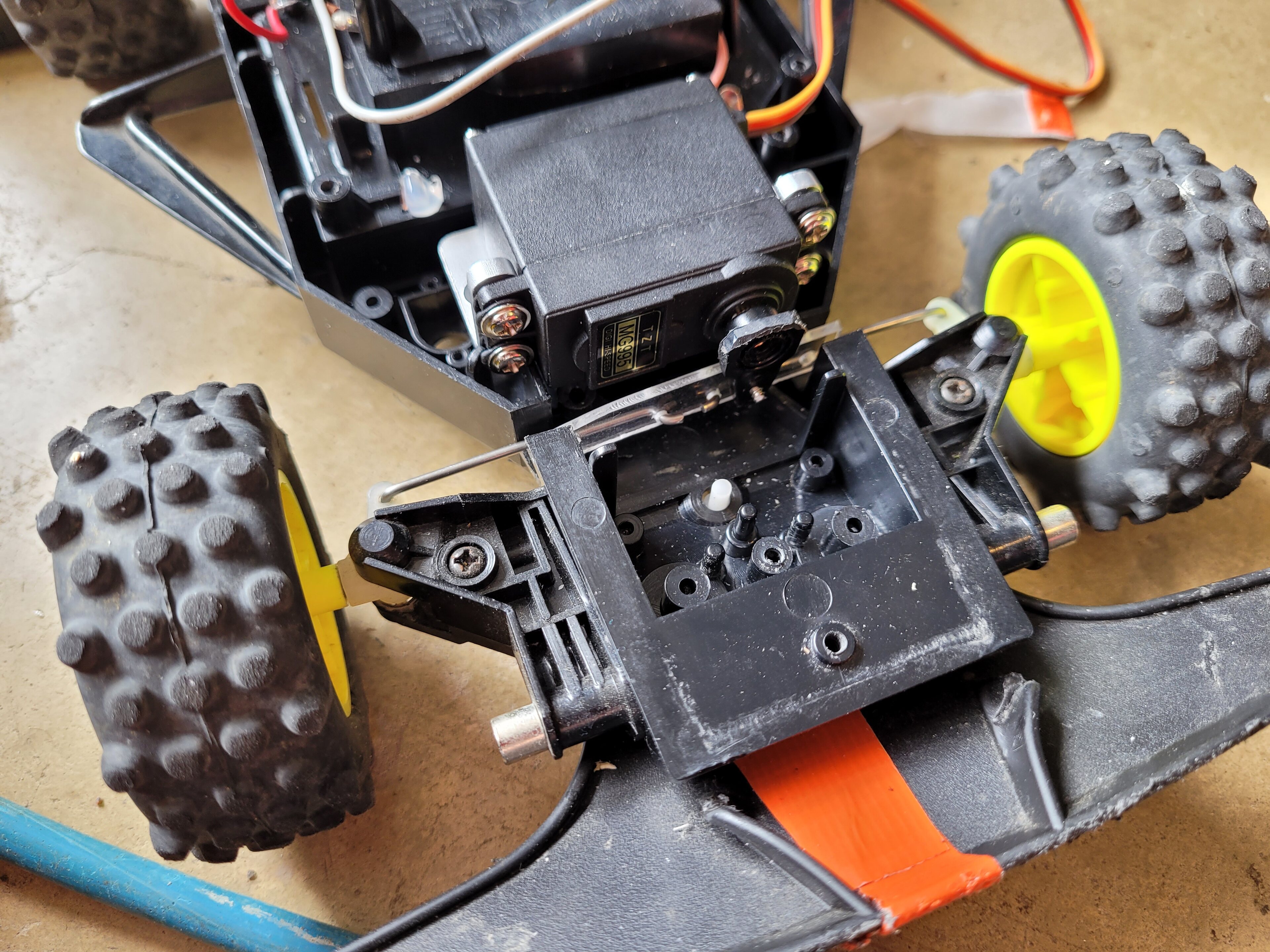
This is one of the earlier narrower brackets, I later found this fouled on the body when I was reassembling it.
I'll put some more details about ESC installation next, but family life is calling.
Once all the parts had arrived, I set up to replace all the electronics. First step was to remove the old electronics and steering motor.
Once I had remove the old internals, I started fitting the new servo and planning new linkages. It turns out I was very fortunate the standard servo fitted in the front of the car, and with the aluminium bracket could be mounted quite easily. I had to trim a little bit of the plastic mounts from the old steering bracket.
As the servo shaft was now off centre, my original plan was to use some M3 adjustable tie rods to the knuckles on each side, but when I started to mock this up, it was quick obvious this wouldn't fit without serious chopping to the original body. Although I am happy to modify it to fit the new internals, I don't want to risk durability to much.
With the tie rods being a no go, I then decided to use the original ~2mm links, with a new bracket. I took a piece of acrylic (because I had some, a less brittle plastic would be better) and mounted the links, as well as one of the plastic servo arms that came with the servo. By keeping the acrylic bracket wider than the chassis, it is prevented from twisting, which helps to keep everything straight despite the offset servo mount, It took 3 acrylic brackets before I was happy with the result.
This is one of the earlier narrower brackets, I later found this fouled on the body when I was reassembling it.
I'll put some more details about ESC installation next, but family life is calling.

With the steering servo sorted, it was time to fit the new ESC. As the 40A esc came with JST connectors for the motor and battery, I decided to solder the matching connectors onto the original wires. I ordered some pre fitted connectors with 5cm of cable from Ebay, and then got the soldering iron out. Fortunately I remembered to heat shrink all the joins, so you can't see my terrible soldering, I need a lot more practice. I can never get the solder to flow as neatly as they do in al the tutorials, probably wrong solder, soldering iron temperature, and I was only born with 2 arms, not the three needed for soldering.
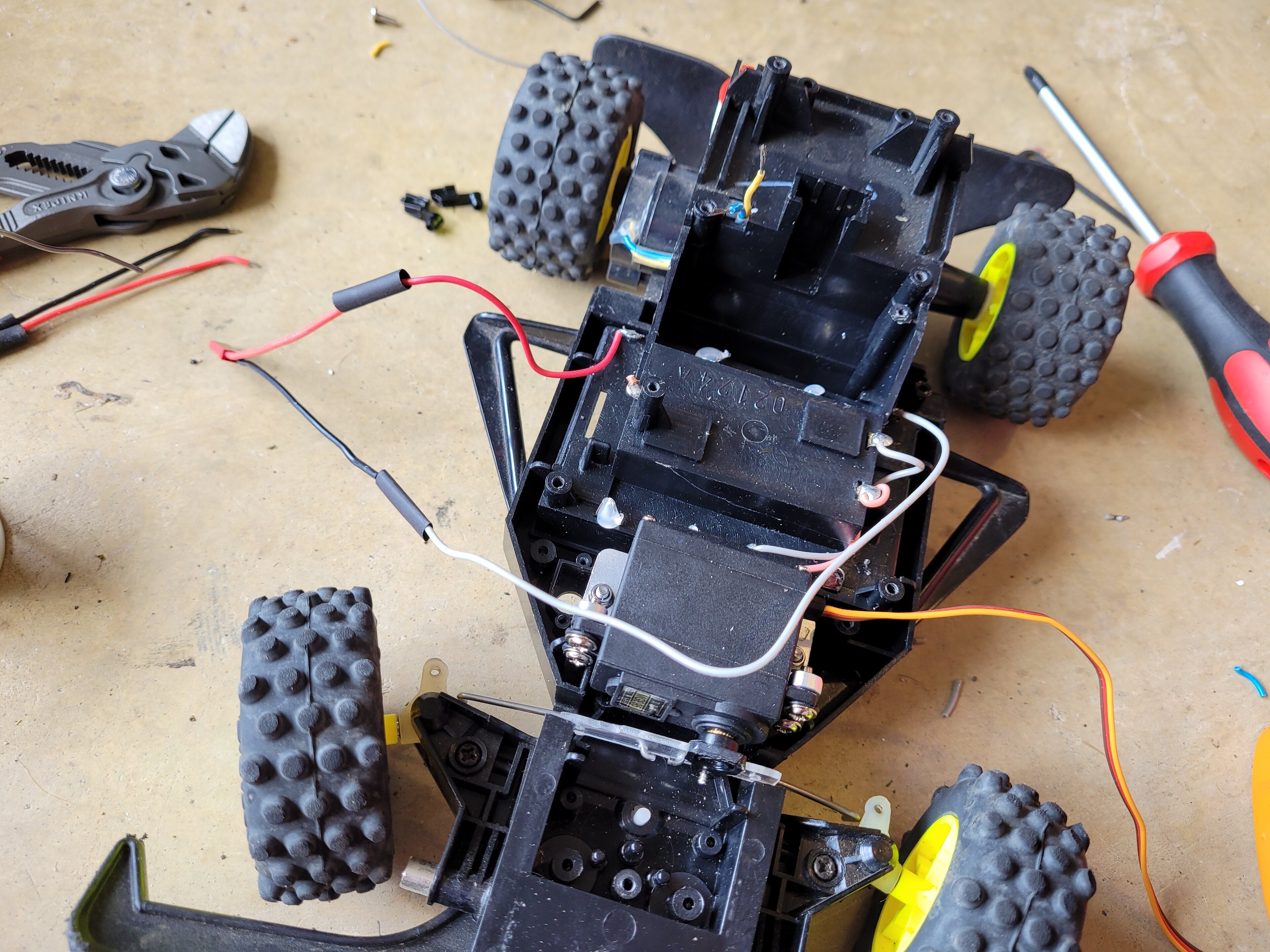
For the motor connectors, I had checked with my voltmeter which was positive and negative when running forwards . backwards and made sure to connect in the same way for the new esc.
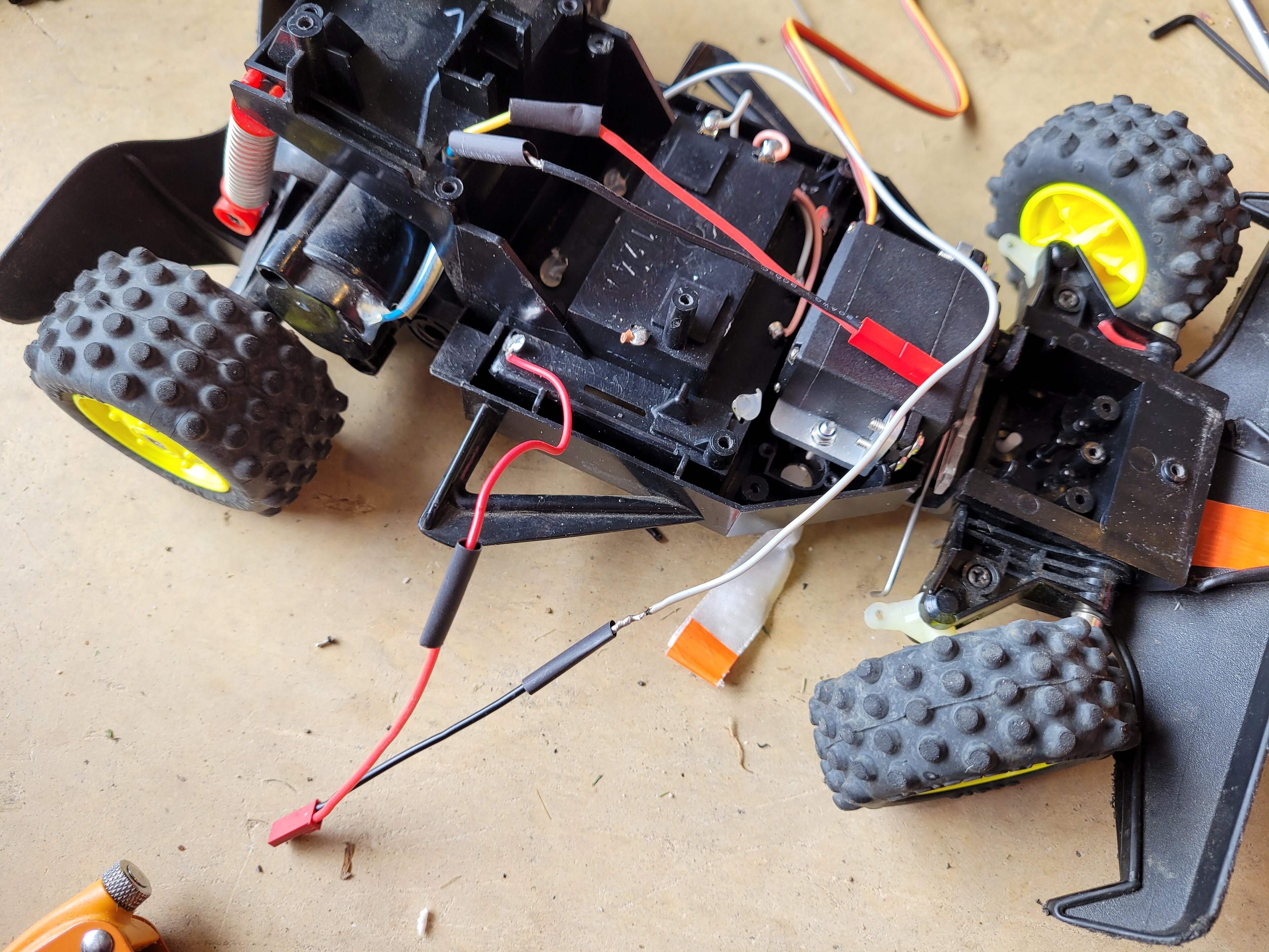
With the soldering done, and once I had found enough batteries for the DumboRC and the car, it was a time to check it all worked, before sticking the ESC and receiver down with some double sided tape
This has the new wider steering bracket on it,

With the wiring slightly tidie, I could screw the body back on, and it was finished. Foolishly, I don't have any photos at this point, but it looks like the picture at the start of the thread. Externally, the big floppy antenna is now removed, and you can just see the ends of the steering bracket, but otherwise it looks mostly stock.
I'm really pleased with the result, its now fully proportional, possibly a little quicker with the esc, and there is no cut out of steering at full throttle.
For the motor connectors, I had checked with my voltmeter which was positive and negative when running forwards . backwards and made sure to connect in the same way for the new esc.
With the soldering done, and once I had found enough batteries for the DumboRC and the car, it was a time to check it all worked, before sticking the ESC and receiver down with some double sided tape
This has the new wider steering bracket on it,
With the wiring slightly tidie, I could screw the body back on, and it was finished. Foolishly, I don't have any photos at this point, but it looks like the picture at the start of the thread. Externally, the big floppy antenna is now removed, and you can just see the ends of the steering bracket, but otherwise it looks mostly stock.
I'm really pleased with the result, its now fully proportional, possibly a little quicker with the esc, and there is no cut out of steering at full throttle.
Although it was now working after the initial conversion, there were some issues.
Firstly, I crashed it into a post and promptly bent the steering arm, it will be interested to see how these hold up, but easily bent back to shape.

The other issue I had required new parts, the ESC that I had picked had an automatic low battery cut off for LiPO batteries. As this is running with 8 AA batteries in series, it was recognising it as a 3S LiPO, this meant the cut off was set to suit a 3S LiPO. The issue I had is that NiMH have much more voltage drop under load than a LiPO, so the low voltage would trigger when running full throttle for several seconds, as the voltage would drop that much, although the batteries still had plenty of charge.
The 40a ESC had no manual way to set the battery type back to NiMH, it only auto-detected. I therefore purchased a new 60a ESC from surpass hobby which included a jumper to set between LiPO and NiMH. The cut off for NiMH is much lower than with LiPO, so I shouldn't see any early low voltage warnings.
https://www.aliexpress.com/item/1005001913977267.h...
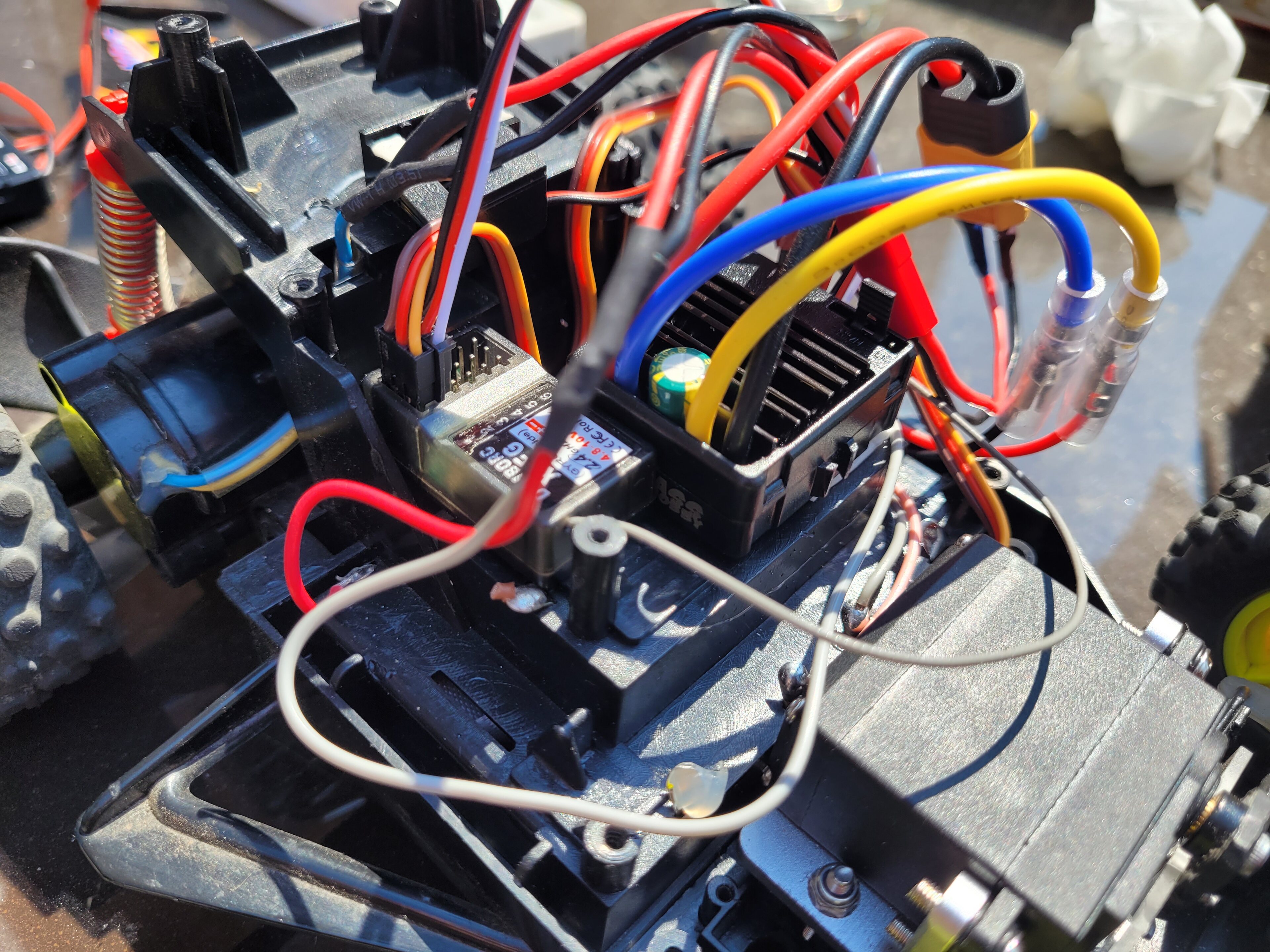
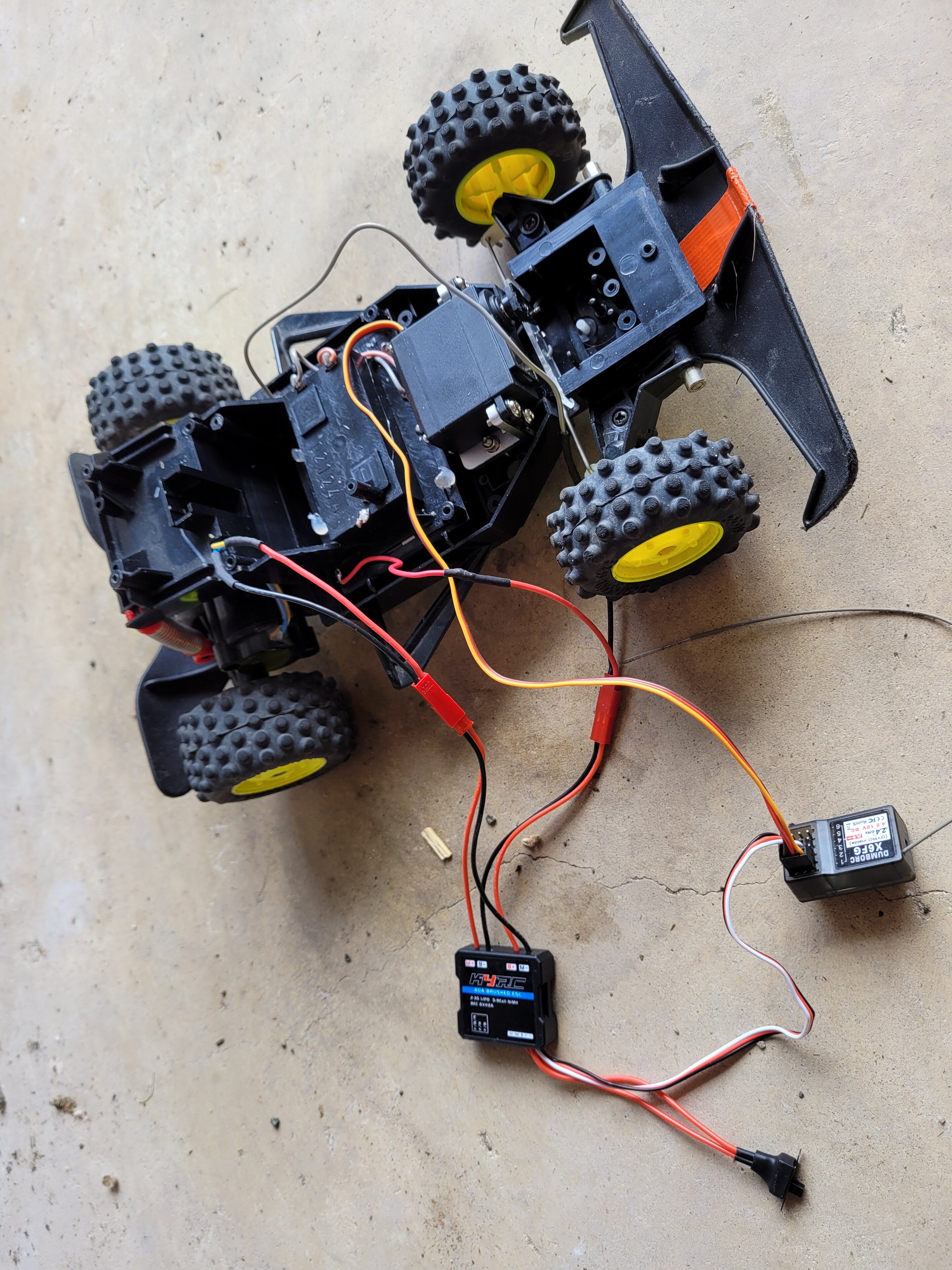
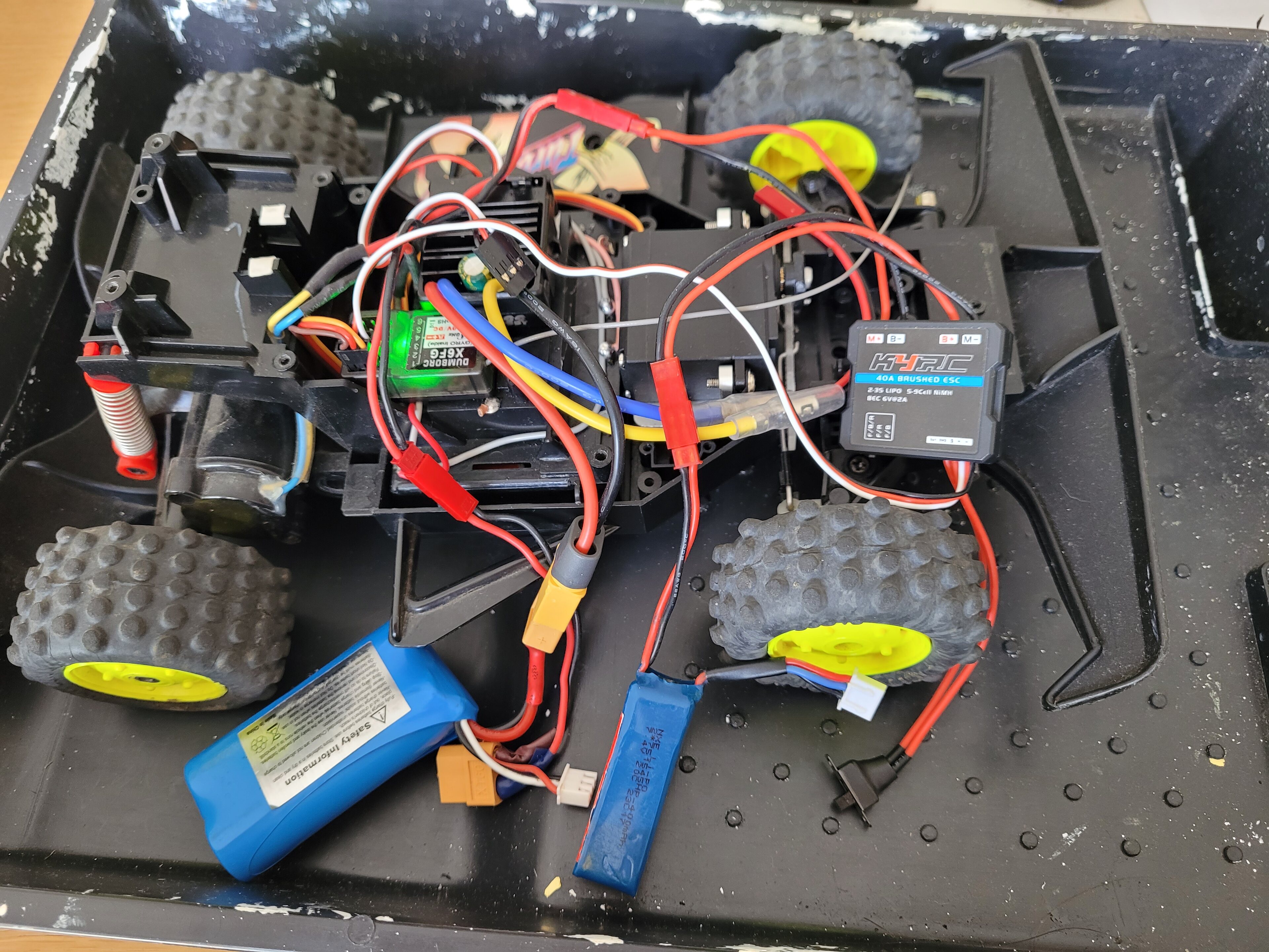
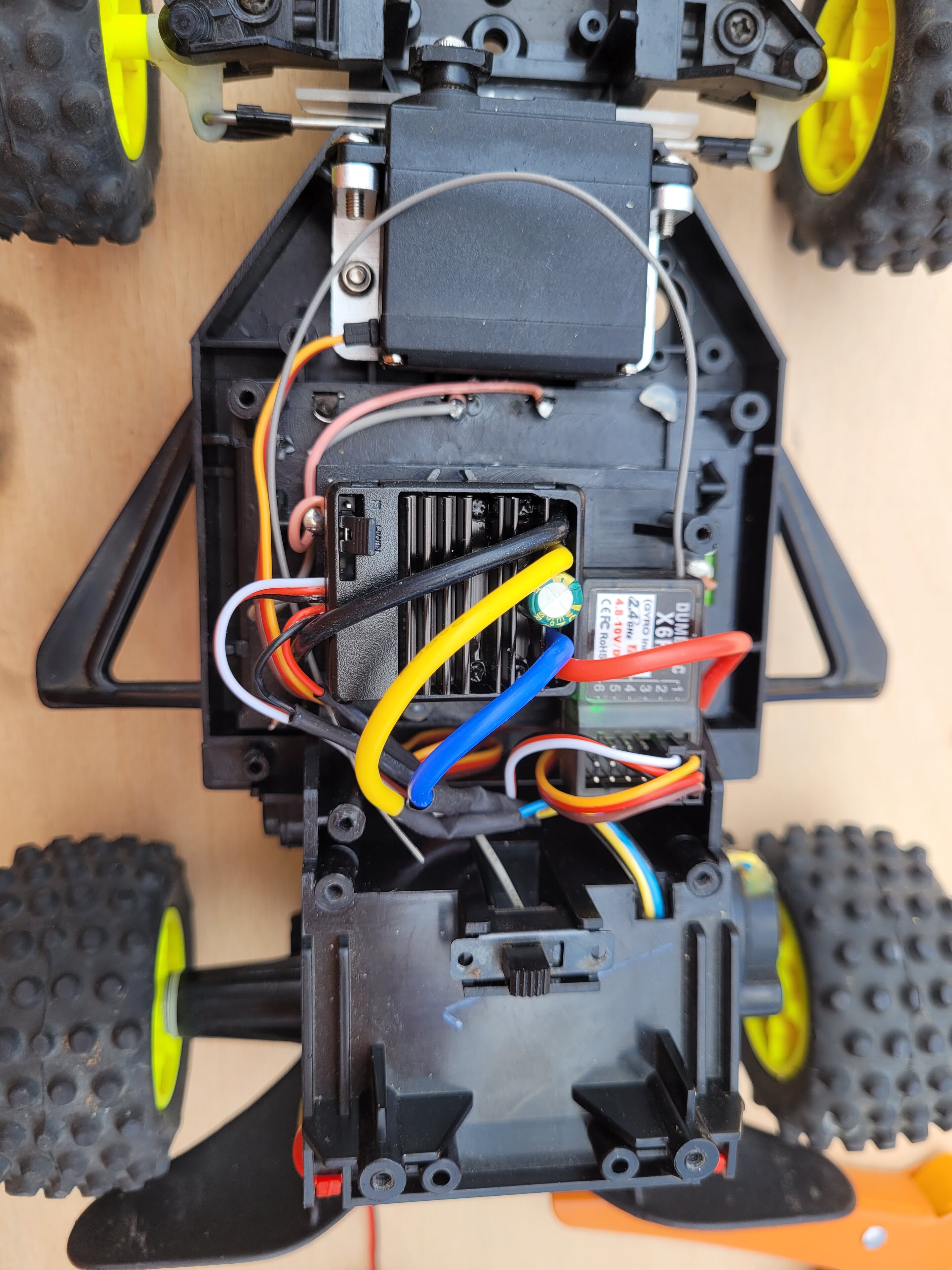
Some excellent wiring spaghetti with the new ESC, one day I might go back and tidy this up, but just used some adapter cables with the JST plugs I soldered previously to do initial testing.
With the new ESC, I went for a quick test drive without the body. The low voltage warning seems resolved, it could stay at full throttle for multiple runs without cutting to 50% throttle.
However, I broke it again. The catch for the battery tray came loose and snapped off, so need to think about how to repair / replace it. As always family duty called again, so maybe later next week.
Firstly, I crashed it into a post and promptly bent the steering arm, it will be interested to see how these hold up, but easily bent back to shape.
The other issue I had required new parts, the ESC that I had picked had an automatic low battery cut off for LiPO batteries. As this is running with 8 AA batteries in series, it was recognising it as a 3S LiPO, this meant the cut off was set to suit a 3S LiPO. The issue I had is that NiMH have much more voltage drop under load than a LiPO, so the low voltage would trigger when running full throttle for several seconds, as the voltage would drop that much, although the batteries still had plenty of charge.
The 40a ESC had no manual way to set the battery type back to NiMH, it only auto-detected. I therefore purchased a new 60a ESC from surpass hobby which included a jumper to set between LiPO and NiMH. The cut off for NiMH is much lower than with LiPO, so I shouldn't see any early low voltage warnings.
https://www.aliexpress.com/item/1005001913977267.h...
Some excellent wiring spaghetti with the new ESC, one day I might go back and tidy this up, but just used some adapter cables with the JST plugs I soldered previously to do initial testing.
With the new ESC, I went for a quick test drive without the body. The low voltage warning seems resolved, it could stay at full throttle for multiple runs without cutting to 50% throttle.
However, I broke it again. The catch for the battery tray came loose and snapped off, so need to think about how to repair / replace it. As always family duty called again, so maybe later next week.
She lives, well she lived, and now she is dead again.
So last year I kept an ebay search live, and was able to buy a parts car to fix mine with. This was a more modern version that used a 6v brick battery, rather than the AA battery tray, but I was able to reuse the battery catch with a small modification, sorry no pictures of the fix.
The car was running well, but on the most recent run out, my son was using it and declared the battery was flat, but it was a little more serious than that - steering servo was still running perfectly, so strip down and investigation required.
First checked with a different speed controller confirmed my suspicion, the motor has burnt out, this means the spares car particularly comes into its own.
The 60a ESC, along with ~12v is probably a bit much for the motor, so I expect to have the same issue in the future. Plan is to swap the complete axle assembly anyway, and tidy up some of the wiring.
Speed controller test;
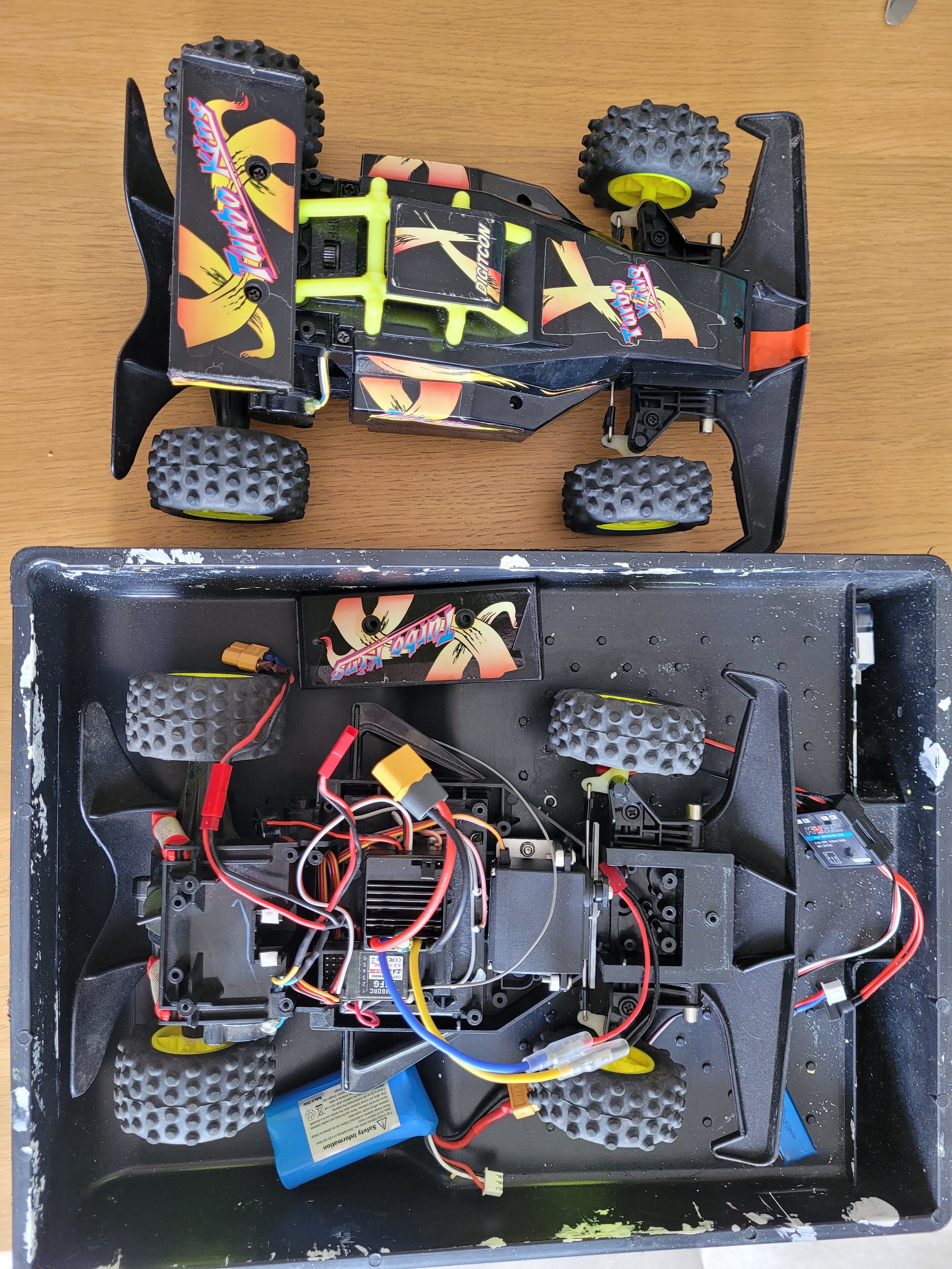
Parts car, branded digitcon rather than Hitari, I already swapped out my broken front bumper.

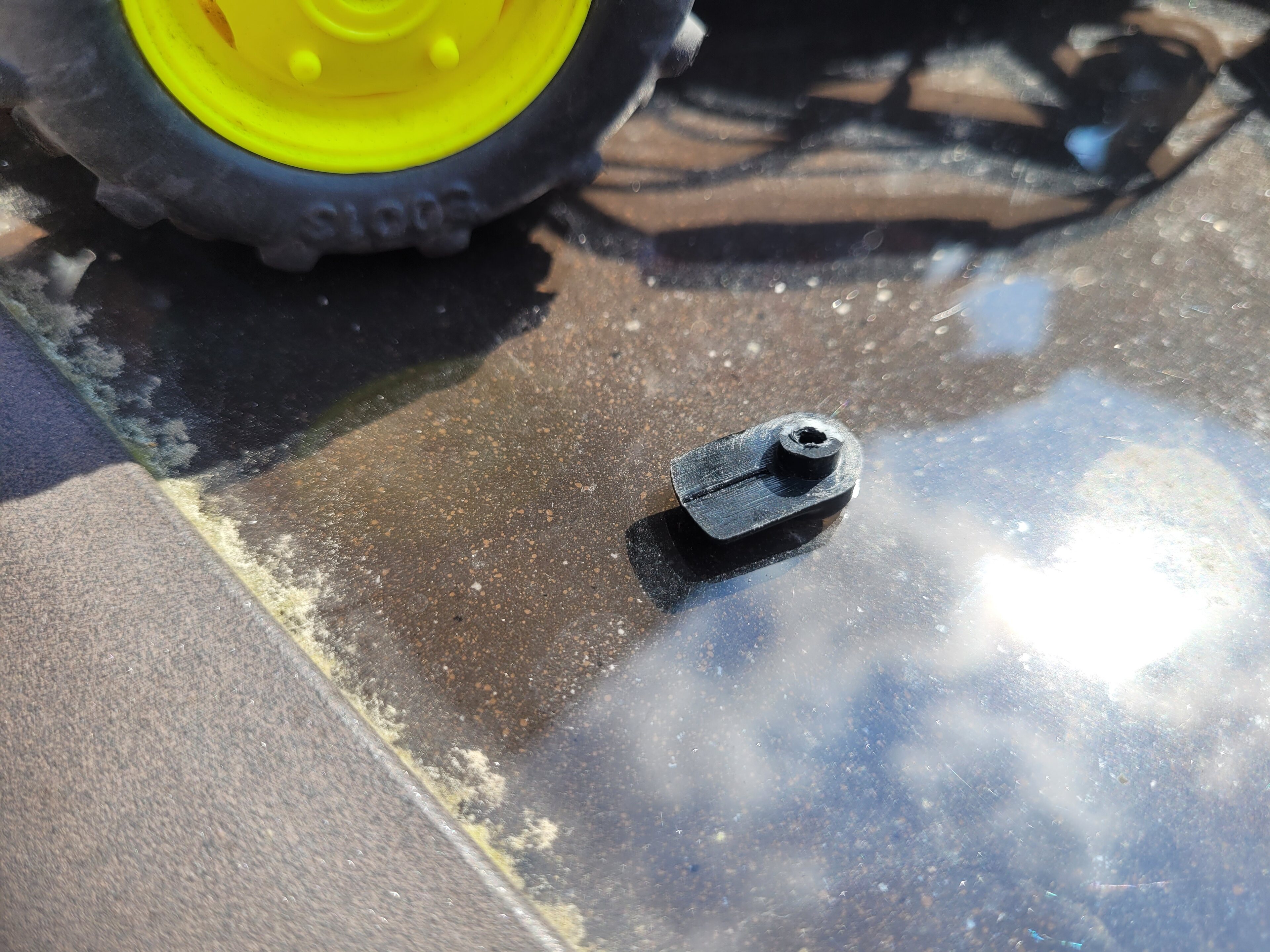
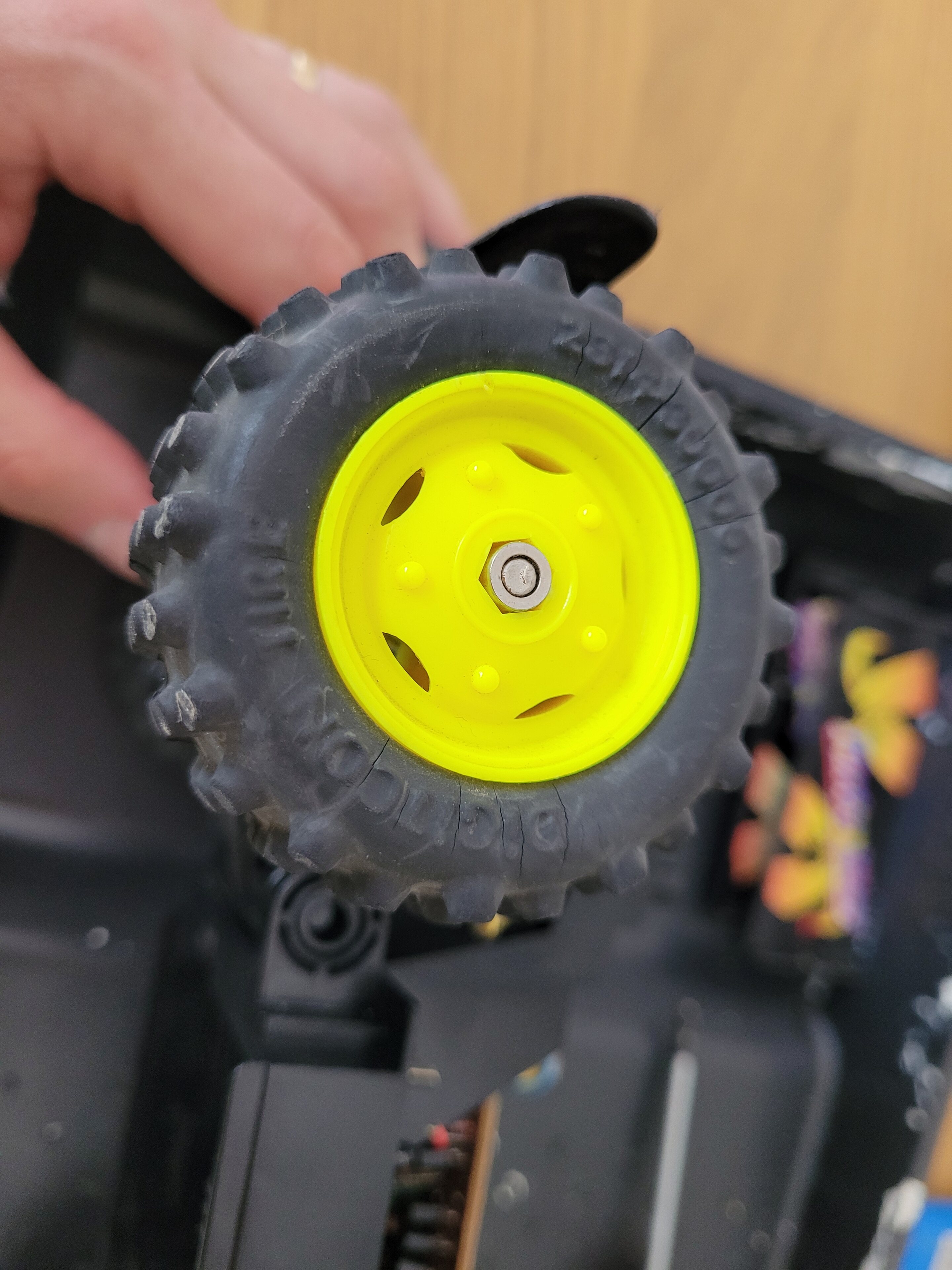
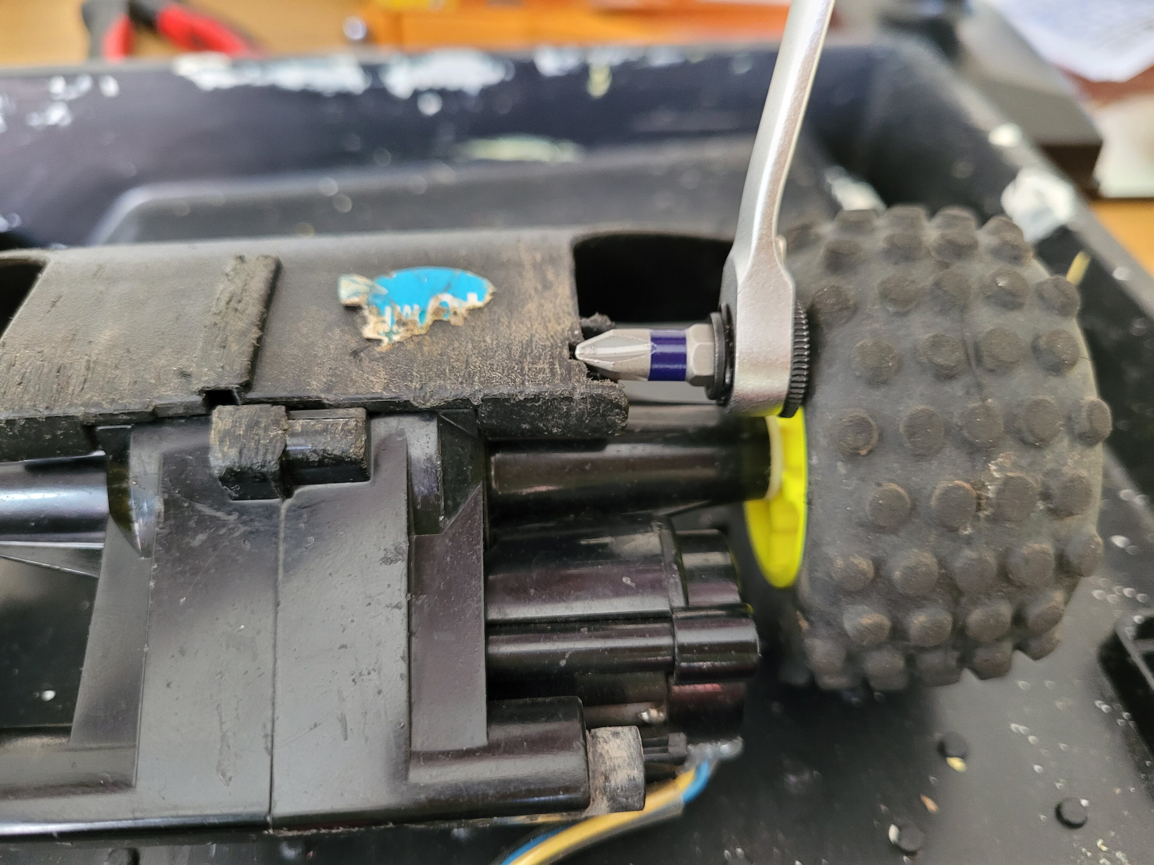
After I've fixed my running car, I want to investigate the burnt out motor, but am struggling to strip it down. I can't access the bumper screw as the wheel is too close, but can't see how the wheels would come off - preferable in one piece. Its a moulded hex on the wheel, but a cylindrical feature on the axle.
Any tips on removal?
So last year I kept an ebay search live, and was able to buy a parts car to fix mine with. This was a more modern version that used a 6v brick battery, rather than the AA battery tray, but I was able to reuse the battery catch with a small modification, sorry no pictures of the fix.
The car was running well, but on the most recent run out, my son was using it and declared the battery was flat, but it was a little more serious than that - steering servo was still running perfectly, so strip down and investigation required.
First checked with a different speed controller confirmed my suspicion, the motor has burnt out, this means the spares car particularly comes into its own.
The 60a ESC, along with ~12v is probably a bit much for the motor, so I expect to have the same issue in the future. Plan is to swap the complete axle assembly anyway, and tidy up some of the wiring.
Speed controller test;
Parts car, branded digitcon rather than Hitari, I already swapped out my broken front bumper.
After I've fixed my running car, I want to investigate the burnt out motor, but am struggling to strip it down. I can't access the bumper screw as the wheel is too close, but can't see how the wheels would come off - preferable in one piece. Its a moulded hex on the wheel, but a cylindrical feature on the axle.
Any tips on removal?
Morning,
Any chance you can drill 1 or 2 very small indentation on the flat surface of that cylindrical’’nut’ using a very fine drill bit?
Then, if you can achieve that, which will take some patience I appreciate. Then use a fine pointed instrument like a scriber or similar inserted into indentation and tap with a small hammer anti-clockwise ( I guess) and ‘walk’ the nut backwards. Just enough to it starts to back off enough - then get some fine nose pliers on it as it clears the surface of the wheel.
I hope that makes sense?
Edit: just been thinking about this on the way to work.
It’s a strange set up and difficult to understand how it was assembled in the first place. Are you sure it’s a ‘nut’ threaded on the shaft? Obviously you are going to have to try and work out a way to lock that shaft the drive nut tightens.
It looks 2wD and assuming that nut is on the drive axle? And it has a differential in gearbox? So assume you can’t lock the drive by holding the opposite wheel?
Edited by Jim H on Thursday 9th May 06:28
Thanks Jim,
It does have an open diff, so can't hold the opposite wheel, but can hold the wheel on the same side, as it is obviously locked to the drive shaft.
I suspect they have a press fit, as they wouldn't have planned for it to be dismantled and replaced. I would prefer not to destroy the wheels if we could avoid it but may have to press it off, but I don't think the plastic will be up for it.
Sacrificial bit is a good try, it would need to be very short though, as it needs to allow for the screw to come out as well.
Max, Exactly what you have already assumed, I also suspect they must be some sort of ‘press fit / friction fit’.
Totally agree.
I’d really discount it being a threaded shaft / nut arrangement. Speed and time is essentially the logic on these type of assemblies.
I helped a mate out last week who was trying to free up jammed carburettor barrel on an old two stroke RC engine.
I suggested boiling hot water. Heat is always preferable in these situations - not excessive. It did the job for my mate.
I obviously understand you don’t want to distort the plastic. But very hot water and gentle persuasion may give you an idea what you are fighting against. Mechanically.
Good luck and report back.
Edit: Very short hex bit just to get the head of the screw turning just enough outside of its enclosed indented hole.
Fine nosed pliers after that?
Edited by Jim H on Thursday 9th May 22:23
As always, a tale of two halves.
I successfully fitted the replacement motor & axle assembly, and feeling pleased with myself finally tidied up the wiring, so cut off all the extra connectors and directly soldered everything (annoying motor wires were flipped, so yellow to blue and blue to yellow). Looked much smarter inside the model.
Feeling pleased with myself I took it for a run, only to burn out the next motor within 15 minutes. Would be interesting if they were different motor specs, technically this motor came from a car that was only running at 6V, not the 12 I was running out.
With this set back I returned to the axle disassembly, but still no luck in disassembly. I have taken all the screws out the casing, but the metal rod is a reinforcement through the entire axle, so I can't split the case while it is still in tact. I think I will have to get destructive. I tried heat to remove the end rivets, but with no luck so far.
In more exciting news, I might have accidentally ordered one of these, it'll probably be more reliable until I inevitably crash it into something.
WLToys 124008
Hi, I've been reading with interest.
I've also got a Turbo King. Had it from new, 25yrs ago. Still works perfectly. It's the 8 x AA version.
I also had the battery cover catch break but fixed by drilling a hole through the catch and attaching with a hex head bolt, been bulletproof since.
I'd love to know how to keep the "turbo" straight line performance whilst cornering, rather than it derating the power, but I assume that's not a straightforward tweak to apply?
Cheers
mk1storm said:
Hi, I've been reading with interest.
I've also got a Turbo King. Had it from new, 25yrs ago. Still works perfectly. It's the 8 x AA version.
I also had the battery cover catch break but fixed by drilling a hole through the catch and attaching with a hex head bolt, been bulletproof since.
I'd love to know how to keep the "turbo" straight line performance whilst cornering, rather than it derating the power, but I assume that's not a straightforward tweak to apply?
Cheers
Unfortunately, I think the reduction in power during cornering is a limitation of the stock electronics, so the only change would be to undertake fairly serious modification's like I have. Considering the success I've had with burning out drive motors on mine - not sure I would recommend it if you like how it is running nowI've also got a Turbo King. Had it from new, 25yrs ago. Still works perfectly. It's the 8 x AA version.
I also had the battery cover catch break but fixed by drilling a hole through the catch and attaching with a hex head bolt, been bulletproof since.
I'd love to know how to keep the "turbo" straight line performance whilst cornering, rather than it derating the power, but I assume that's not a straightforward tweak to apply?
Cheers
Gassing Station | Scale Models | Top of Page | What's New | My Stuff