Instructions to change fuel maps on 14CUX Griffith, Chimaera
Discussion


I checked with Colin. He doesn't have great confidence in the curve fitting function. Then I repeated what Erik did and got the same results as Erik. I then asked Colin to update the RoverGauge code using the data table instead of a function. The error seams to accumulate at the ends of the range (very hot or very cold) which may be why it was never noticed until now. I'm confident that the previously posted table (pg 19) is more accurate than what the function produced and is what Colin was actually aiming for. Thanks to Erik for bringing this forward.
Expect a new version of RG soon.
Expect a new version of RG soon.
I need some help from the experts. I would like to adjust two tables for which I have insufficient information to know what I'm doing.
1) At the moment the car is running very rich after starting. Therefore I want to reduce the startup enrichment, especially at low temperatures. This is the 12x3 table that is present in each map. I assume the first row is the temperature, if the current temperature is below two values, does it use the left (higher temperature) or right colum of the table?
What is the "cranking value"? Is this a multiplier for the injector duty cycle or is it added to the duty cycle? With what significance is it added (e.g. how big is the impact of 1 lsb)?
How many bits is the final injector dutycycle used in the timer? Assuming 8 bits for the map + 16 bits for the multiplier would say 24 bits, but given the clock frequency of the processor this seems highly unlikely.
Does the start up enrichment only use the column that is applicable at startup or does it step through each of the columns to the left (including the ones for a very hot engine)?
2) Yesterday we did a dyno run of the 5.2L. During mapping we found the throttle enrichment quite severe, therefore we would like to reduce the throttle enrichment to prevent very high and very low AFR's. What do the columns represent? Is it again a coolant temperature value?
How do the opening and closing limits work? Why is the opening multiplier divided over two rows, is it a 16 bit value?
What value for the opening and closing multiplier represents "1" (no change) and what is a value larger/smaller than "1"?
I hope someone can answer these questions who has been looking into the assembly code a lot or has experience. It might be useful to collect all information relevant for adjusting the ECU on a single webpage, e.g. at stevesprint's server.
Erik, if I remember correctly, when the coolant temperature count is between two values in the first row, the column to the right is used. Also, normally the software does keep refreshing the values, so the active column slides to the left as the engine warms.
The 2nd row values in the 12x3 table are used for cranking fuel only and are no longer used once the engine starts. So the 2nd row is probably not what you want to change. The 3rd row values are used in an unusual way. These values are treated both as time (seconds) and also as a numerical addition to the fueling value. Contrary to what I said above, this is one value that is only selected from the table once at startup. It is also decremented by a counter at the rate of 1 Hz.
As an example, if a value of 15 is selected from the table at startup. That value would be added to the fuel enrichment for one second, then 14 is added for the next second, and on down to zero. Looking at the 3rd row values, you can see that this enrichment decreases and phases out very quickly (less than 1 minute). Do you think this will solve your problem? If not, you should look at the 8x3 table just below the 12x3 table.
The 8x3 table creates a fuel enrichment curve that follows the coolant temperature count. If you understand how the RPM curve works, it may help here. The column values work together to create a smooth curve from one bracket to the next so I would not change anything (at least permanently) without modeling. If you think you need to change this table to solve your problem, you may try sliding just the top row to the left 1 or 2 columns. Don't move or change the last two rows.
danbourassa said:
I checked with Colin. He doesn't have great confidence in the curve fitting function. Then I repeated what Erik did and got the same results as Erik. I then asked Colin to update the RoverGauge code using the data table instead of a function. The error seams to accumulate at the ends of the range (very hot or very cold) which may be why it was never noticed until now. I'm confident that the previously posted table (pg 19) is more accurate than what the function produced and is what Colin was actually aiming for. Thanks to Erik for bringing this forward.
Expect a new version of RG soon.
New version (0.8.4) has been posted:Expect a new version of RG soon.
https://github.com/colinbourassa/rovergauge/releas...
It was actually the backend library (libcomm14cux) that changed. Windows users can just download the latest .zip file as usual. Linux users will need to update the library separately.
To reiterate, this version switches to using a lookup table for coolant temperature and fuel temperature readings. This should be more accurate than the previous version, especially for very high and very low temps.
Griffian said:
It does look good. After a bit more research, the other minor negatives to this 'budget' unit are:
Griffian- The processor is a little slower than on their premium products so may have a slower sampling rate. I expect it will still be much faster than the 14CUX though.
- The VSS input probably won't have the ideal resolution for multiple pulses per wheel revolution. It would work better with an additional sensor or some kind of electronic waveform divider.
- It requires initial free-air calibration when a new sensor is used as it doesn't use the manufacturer's calibration resistor.
- I would check it can output 2 or more readings per second
- I wouldn't worry too much about the road speed, as you know its not required for remapping but useful to know your AFR at set speeds like cruising on the motorway. Could you use a hardware signal generator to convert the road speed pulses to a varying 0 - 5v signal like Dan suggests would have been better for the 14CUX.
- Also don’t worry about the free air calibration, I had to calibrate my LC2 sensor, its very quick and easy.
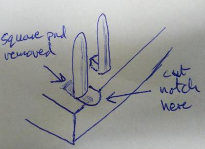
Thanks for your clear sketch. I’ve since bought an Aries 28-526-10 socket and now see exactly what you mean about removing the small square standoff to make room to loop the wire around the pin before soldering. Neat!!
TomcatErik said:
I have three more questions to the experts of the 14CUX injection system.
1) After reading the book on power tuning the rover V8 I decided to change the thermostat to a 74-78C. As a result the nominal engine temperature is now 77C as read with rovergauge. What should I edit in the cold-start enrichment table to prevent enrichment above 74C?
2) At the moment, no speedo signal is connected to the ECU. What are the adverse effects, other than a MIL light for speedo sensor error?
3) I'm still having a problem with the idle control. I cleaned the IACV by disassembling it, cleaning it and reassembling it with a bit of WD40. After starting the idle control works fine. However, after bit of driving the stepper drifts away to fully open with the ECY thinking it is closed. Changing to another used and cleaned unit gives the same problem.
For the speedo signal, we have a TD5 transfer box with the original 3-wire TD5 speed transducer. This transducer gives an output of 0V to 12V (battery voltage) square wave. Can I connect this directly to the ECU or do I need to bring the signal down to 5V?
1. I’m not sure about the adjustment factor based on engine temperature table and never experimented with it but hopefully Dan’s suggestion will help.1) After reading the book on power tuning the rover V8 I decided to change the thermostat to a 74-78C. As a result the nominal engine temperature is now 77C as read with rovergauge. What should I edit in the cold-start enrichment table to prevent enrichment above 74C?
2) At the moment, no speedo signal is connected to the ECU. What are the adverse effects, other than a MIL light for speedo sensor error?
3) I'm still having a problem with the idle control. I cleaned the IACV by disassembling it, cleaning it and reassembling it with a bit of WD40. After starting the idle control works fine. However, after bit of driving the stepper drifts away to fully open with the ECY thinking it is closed. Changing to another used and cleaned unit gives the same problem.
For the speedo signal, we have a TD5 transfer box with the original 3-wire TD5 speed transducer. This transducer gives an output of 0V to 12V (battery voltage) square wave. Can I connect this directly to the ECU or do I need to bring the signal down to 5V?
2.3. I can also confirm from personal experience point 3 is caused by point 2 and yes you can safely connect the +12v sign wave from your transducer direct to the ECU road speed sensor input. Do not bring it down to 5 volts. If you still experience issues Dan has shown us how to change the road speed input sensitivity by changing the road speed comparator in the RoadSpeed.asm.
rdSpdCompTest   ldaa        #$27                ; [2] SC=0 PC=1  Set comparator mode on ch 7 (RS)
                staa        AdcControlReg1      ; [4] Hitachi says write this reg starts conversion
                ldaa        #$C8                ; [2] load compare value (to determine high or low)
Also some people suggest using a 120 ohms resistor or diode in series to alter the sensitivity.
Dan has also shown DaveP how to change the road speed calibration in the code.
TomcatErik said:
For the idle control, could we change the code to allow some degree of
"overstepping" to always have idle control. Also when the stepper is not in perfect condition.
Interesting, you could change the coolant temperature based idle control table at prom offset C17B to overstep the stepper to increase the coasting and initial starting idle but not only when the stepper is not in perfect condition."overstepping" to always have idle control. Also when the stepper is not in perfect condition.
I’ve personally always thought the code deliberately stalls the engine when their is no road speed signal as it would be too easy to pull the VSS fuse to eliminate the road speed limiter and stop running up the miles on the clock. The only other way is to have a clutch pedal switch input so the ECU knows when the transmission is disconnected or is your Tomcat automatic.
TomcatErik said:
It might be useful to collect all information relevant for adjusting the ECU on a single webpage, e.g. at stevesprint's server.
I plan to update my web pages this winter in particular the prom addresses page, I'll add the coolant based table with Dan's notes plus the extended data repeated in the 5 maps. I'm also thinking about creating a code page with the popular code mods we've learnt.Steve
danbourassa said:
I checked with Colin. He doesn't have great confidence in the curve fitting function. Then I repeated what Erik did and got the same results as Erik. I then asked Colin to update the RoverGauge code using the data table instead of a function. The error seams to accumulate at the ends of the range (very hot or very cold) which may be why it was never noticed until now. I'm confident that the previously posted table (pg 19) is more accurate than what the function produced and is what Colin was actually aiming for. Thanks to Erik for bringing this forward.
Expect a new version of RG soon.
Everyone, please don't panic about the accuracy of RoverGauge's temperature guages, they have always been accurate from -10 degs C up to 100 degs C which is within normal operating temperatures. Dan & Erik are only talking about the very extreme temperatures that I hope no one experiences, i.e. below -10 deg C & above 100 deg C.Expect a new version of RG soon.
Here's Dan's 8-bit coolant sensor reading to temperature in degrees C table with his explanation below.
    0   1   2   3   4   5   6   7   8   9   A   B   C   D   E   F
0  130,129,127,126,124,123,121,120,118,117,115,114,112,111,109,108, 0
1  106,105,104,103,102,101,100, 99, 98, 97, 96, 95, 94, 93, 92, 91, 1
2   90, 89, 88, 87, 86, 85, 84, 83, 82, 81, 80, 79, 78, 77, 76, 75, 2
3   74, 73, 72, 71, 70, 70, 69, 68, 67, 66, 65, 64, 63, 63, 62, 61, 3
4   60, 59, 59, 58, 58, 57, 56, 56, 55, 55, 54, 54, 53, 52, 52, 51, 4
5   51, 50, 50, 49, 49, 48, 48, 47, 47, 46, 46, 45, 45, 44, 44, 43, 5
6   43, 42, 42, 41, 41, 40, 40, 39, 39, 38, 38, 37, 37, 36, 36, 35, 6
7   35, 35, 34, 34, 33, 33, 32, 32, 31, 31, 30, 30, 29, 29, 28, 28, 7
8   28, 28, 27, 27, 26, 26, 26, 25, 25, 24, 24, 23, 23, 23, 22, 22, 8
9   22, 21, 21, 20, 20, 19, 19, 18, 18, 17, 17, 16, 16, 15, 15, 14, 9
A   14, 14, 13, 13, 12, 12, 11, 11, 10, 10,  9,  9,  8,  8,  7,  7, A
B    7,  7,  6,  6,  6,  5,  5,  5,  4,  4,  3,  3,  3,  2,  2,  2, B
C    2,  1,  1,  0,  0, -1, -1, -2, -2, -3, -3, -4, -4, -5, -5, -6, C
D   -6, -6, -7, -7, -8, -8, -8, -9, -9,-10,-10,-11,-11,-11,-12,-12, D
E  -12,-13,-13,-14,-14,-15,-15,-16,-16,-17,-17,-18,-18,-19,-19,-20, E
F  -20,-20,-21,-21,-22,-22,-22,-23,-23,-23,-24,-24,-24,-25,-25,-25  F
    0   1   2   3   4   5   6   7   8   9   A   B   C   D   E   F
0x27 would be 2 down and 7 across (first down then across). The coolant table is arranged 16 x 16 so it matches up nicely with hex values. This is just a calibration table that we refer to often in order to understand the 14CUX software better. It's not in the 14CUX code at all.
stevesprint said:
- I would check it can output 2 or more readings per second
stevesprint said:
- I wouldn't worry too much about the road speed, as you know its not required for remapping but useful to know your AFR at set speeds like cruising on the motorway. Could you use a hardware signal generator to convert the road speed pulses to a varying 0 - 5v signal like Dan suggests would have been better for the 14CUX.
The sensors are back in stock so I've paid now and it should be on its way to me shortly. No excuses now - I need to get my hands dirty!
Do we have any definitive numbers for the number of pulses per road distance the ECU is expecting from the road speed sensor?
I read something from a Morgan document saying the old cable driven speedo transducer generated 6 pulses per wheel revolution, but I don't know what wheel circumference that assumes (presumably a large Land/Range Rover one). I also found these early posts on this thread where stevesprint found a figure of 8000 pulses per mile This boils down to 9.8 pulses per wheel turn for my tyre size so 3 per propshaft rotation at a diff ratio of 3.31:1.
The reason I ask is in part the perennial TVR speed calibration unit question, and partly to give a speed input to my new O2 sensor. I cant lop teeth off as the signal drives the dash speedo, but I'm thinking about knocking up a box of tricks to take the T5 TVR style signal and divide it to a slower rate to suit my O2 sensor, and if I can generate something which the ECU will tolerate it would be a nice bonus.
The second question is what the ECU code contains in the way of calculations/constants and assuming I can get the pulse frquency into the right ball-park, whether the ECU could be calibrated to my setup. In my view it's easier to keep the hardware simple by dividing by powers of 2 and to tweak the software. With the BIG assumption that the numbers and arithmetic is correct, the Griff sensor gives 53 pulses per wheel turn, my 02 sensor wants about 1 and the ECU wants about 10. In theory, I could divide the pulses by 4 or 8 for the ECU and by 64 for the O2 sensor.
I do realise that the ECU speed calculation comes with a health warning, but I'm sort of banking on Dan producing some magic with his code optimisations and in the meantime, close enough is good enough!
I read something from a Morgan document saying the old cable driven speedo transducer generated 6 pulses per wheel revolution, but I don't know what wheel circumference that assumes (presumably a large Land/Range Rover one). I also found these early posts on this thread where stevesprint found a figure of 8000 pulses per mile This boils down to 9.8 pulses per wheel turn for my tyre size so 3 per propshaft rotation at a diff ratio of 3.31:1.
stevesprint said:
I've reduce the teeth on the wheel down to 4. 16 teeth use to throw the ECU into error and 8 teeth use to hit the ECU road speed limiter. 3.5 teeth would be spot on but without RoverGauge I wouldn't even know it was over reading.
stevesprint said:
I’ve noticed the following on the ACT website about 1/3 down the page.
“The signal should go up and down between 0-2.0 Volts and 10.5-13.0 Volts, changing every 4-5 metres. This signal is 8000 pulses per mile”.
“The reed switch is mounted on a simple circuit board in series with a 120 Ohm resistor”.
http://www.actproducts.co.uk/2011/lucas-14cux-fuel...
This is much slower than the rate the Griff sensor is giving from the 16 toothed wheel and sounds plausible as I would guess the worm gear driven LT77 sensors generated fewer pulses per rotation than the propshaft trigger wheel.“The signal should go up and down between 0-2.0 Volts and 10.5-13.0 Volts, changing every 4-5 metres. This signal is 8000 pulses per mile”.
“The reed switch is mounted on a simple circuit board in series with a 120 Ohm resistor”.
http://www.actproducts.co.uk/2011/lucas-14cux-fuel...
The reason I ask is in part the perennial TVR speed calibration unit question, and partly to give a speed input to my new O2 sensor. I cant lop teeth off as the signal drives the dash speedo, but I'm thinking about knocking up a box of tricks to take the T5 TVR style signal and divide it to a slower rate to suit my O2 sensor, and if I can generate something which the ECU will tolerate it would be a nice bonus.
The second question is what the ECU code contains in the way of calculations/constants and assuming I can get the pulse frquency into the right ball-park, whether the ECU could be calibrated to my setup. In my view it's easier to keep the hardware simple by dividing by powers of 2 and to tweak the software. With the BIG assumption that the numbers and arithmetic is correct, the Griff sensor gives 53 pulses per wheel turn, my 02 sensor wants about 1 and the ECU wants about 10. In theory, I could divide the pulses by 4 or 8 for the ECU and by 64 for the O2 sensor.
I do realise that the ECU speed calculation comes with a health warning, but I'm sort of banking on Dan producing some magic with his code optimisations and in the meantime, close enough is good enough!
Hi guys !
I am new here, and I would like first to thank everyone that has done things to make the 14CUX understandable and possible to remap !
My dad and I have a 1990 Range Rover Classic 3.9 V8 since a few years, on which we worked a lot since we have it. We made a few improvement on the engine, such as Kent H180 camshaft and catalytic converters removed. My father discover RoverGauge, and started to read things about the 14CUX and how to change the eprom. We changed the Eprom by an eprom a friend gave us, and it worked better. We changed the tune resistor also as we no longer have catalytic converters.
The past tree months, we completely rebuilt a 4.6 Rover V8 from a Range Rover P38, we we installed it into our car. We swap the whole engine, so we have the new oil pump, the 4.6 plenum and no more ignition distributor. To take care of the ignition, we installed a programmable ignition ECU called Secu3T, which is an Open Source one, it works great and is very cheaper than MegaJolt or MegaSquirt ECU !
Since a few days, I am reading all stuff on SteveSprint web site (Thanks !) and from this forum to try to understand how to remap my self the 14CUX. Therefore I have a few questions...
1. On SteveSprint I found an XDF file to use with TunerPro to be able to read the .BIN files. However I am not able to open all .BIN files, and I think this is because the XDF file I have is for 32k eprom. Is there an XDF file for 16k eprom available or how to open 16k eprom with it ?
2. Even if I didn't manage to open my original .BIN on tunerpro, thanks to the HEX address details, I managed to look at and compare MAP 2 of different eprom, and except the one from my friend, all map are the same for a 3.9, 4.2, 4.3 and 4.6 engine. I thought they would be different. Then I found that there is a Main Scalar table, which is if I understood right, a multiplier numbers that depends on the engine size, is that right ? If I am, it means this is this number that differs from a 3.9 and 4.6 engine ?
I searched but I didn't find the address of this multiplier in the eprom, does anyone know where it is ?
If I want to adapt my current eprom (for the 3.9) to the 4.6, I just have to change this main scalar ?
3. For the Z axis of the fuel table, what do the values from 0 to 255 represent ? A percentage ? Of what ?
4.I have put a tune resistor for non cat engine, and now I cannot access to lambda information on RoverGauge when logging. Is there a mean to have the lambda info logged without making the lambda trim affect the fueling ?
5. I've seen on SteveSprint web site that the CO trim voltage has to be modified for "precat owners". On my car, according to RoverGauge it is at 2.50V. My car has cat, but they have been removed. Should I modify it ?
Thanks in advance for your aswers,
Regards,
Michael
I am new here, and I would like first to thank everyone that has done things to make the 14CUX understandable and possible to remap !
My dad and I have a 1990 Range Rover Classic 3.9 V8 since a few years, on which we worked a lot since we have it. We made a few improvement on the engine, such as Kent H180 camshaft and catalytic converters removed. My father discover RoverGauge, and started to read things about the 14CUX and how to change the eprom. We changed the Eprom by an eprom a friend gave us, and it worked better. We changed the tune resistor also as we no longer have catalytic converters.
The past tree months, we completely rebuilt a 4.6 Rover V8 from a Range Rover P38, we we installed it into our car. We swap the whole engine, so we have the new oil pump, the 4.6 plenum and no more ignition distributor. To take care of the ignition, we installed a programmable ignition ECU called Secu3T, which is an Open Source one, it works great
and is very cheaper than MegaJolt or MegaSquirt ECU ! Since a few days, I am reading all stuff on SteveSprint web site (Thanks !) and from this forum to try to understand how to remap my self the 14CUX. Therefore I have a few questions...
1. On SteveSprint I found an XDF file to use with TunerPro to be able to read the .BIN files. However I am not able to open all .BIN files, and I think this is because the XDF file I have is for 32k eprom. Is there an XDF file for 16k eprom available or how to open 16k eprom with it ?
2. Even if I didn't manage to open my original .BIN on tunerpro, thanks to the HEX address details, I managed to look at and compare MAP 2 of different eprom, and except the one from my friend, all map are the same for a 3.9, 4.2, 4.3 and 4.6 engine. I thought they would be different. Then I found that there is a Main Scalar table, which is if I understood right, a multiplier numbers that depends on the engine size, is that right ? If I am, it means this is this number that differs from a 3.9 and 4.6 engine ?
I searched but I didn't find the address of this multiplier in the eprom, does anyone know where it is ?
If I want to adapt my current eprom (for the 3.9) to the 4.6, I just have to change this main scalar ?
3. For the Z axis of the fuel table, what do the values from 0 to 255 represent ? A percentage ? Of what ?
4.I have put a tune resistor for non cat engine, and now I cannot access to lambda information on RoverGauge when logging. Is there a mean to have the lambda info logged without making the lambda trim affect the fueling ?
5. I've seen on SteveSprint web site that the CO trim voltage has to be modified for "precat owners". On my car, according to RoverGauge it is at 2.50V. My car has cat, but they have been removed. Should I modify it ?
Thanks in advance for your aswers,
Regards,
Michael
Edited by tahiti-range on Friday 19th February 08:32
Before you get too carried away with remapping you need a reliable way of measuring the mixture. The lambda probes fitted as standard are narrow band, and give a large voltage change around 14.7:1 but very little voltage shift above and below this. Having said that if you can accurately read the voltage from the probe directly in the region of 0 to 1.4 volts you can get a rough idea of the overall fuelling. Typically 1 volt is 14.7, 1.2 is around 14.1 and 1.3 is around 13.5:1- but this does vary depending on the age of the probe but it will give a rough idea. You have to measure this directly on the non cat map with a test meter off the back of the probe, (black and white connections) and it must be connected to the loom still. Rovergauge is no use for this measurement on the green map. Much better would be to fit a wide band probe and AFR meter for accuracy. You really cant start any mapping process by guesswork.
You need the 14cux toolkit to duplicate the 16k to 32k region if you cant read some bins.
The fuel table values on 0 to 255 are simply a value of zero to maximum fuel- its a number used to control the injector timing along with the multiplier. Tuner pro can display it in decimal or hex. This are the values you increase or decrease to add or reduce fuel at the individual load points.
Id leave the CO trim enabled personally- its nice to be able to tweek the mixture from the side of the AFM rather than set in stone in the Eprom- Steve simply set the value in the Eprom that was spot on for his engine- yours may not be the same.
Edited by blitzracing on Friday 19th February 11:05
Thanks, I used 14CUX toolkit, and I am now able to open my map on Tunerpro, but I have a new problem... my eprom is a R2419, and I think the XDF file is for eprom after R2666 as I get very strange fuel map, I think address are not correct 
EDIT: ok, I found that there are map for 2422 and older table and for main scalar... my bad. Are the other values (row scalars (I got FF...) limits, temperature fuel table, good for any revision ?
EDIT: ok, I found that there are map for 2422 and older table and for main scalar... my bad. Are the other values (row scalars (I got FF...) limits, temperature fuel table, good for any revision ?
Edited by tahiti-range on Friday 19th February 21:57
Edited by tahiti-range on Friday 19th February 22:58
blitzracing, when you talk about measuring the voltage with a test meter off the back of the probe still connected to the loom, you mean it still have to be connected to the 14CUX while measuring ?
I have a very good voltmeter that I can calibrate around a value, and also a portable oscilloscope, what would you suggest to be the best ?
I will in the future buy a wind range lambda, but not right now, I would like to be familiar with 14CUX first.
I have a question about the multiplier, how does it work ? I mean, it simply multiplies the fuel map by a constant value, or is it dependant on other parameters ?
I did compare map from 3.9-4.2-4.3 and 4.6 engines, and this multiplier and the row scalar are the main differences between the except from slight differences in fuel map.
Is that right to say that it is related to the engine displacement ? Is it possible to adapt a 3.9 eprom to a 4.6 engine just by changing this value ?
In my eprom, using xdf file from Steve web site, I have Tracing map fuel blue and white, what are these table for ?
Also, the what are the address of the Throttle Table, the Start up enrichment, and the Temperature Fuel Multiplier table in the eprom ? As my eprom is a 2419 rev, I changed the address for nearly all the map and scalars in the XDF, but I didn't find where are the precedent map.
Thanks in advance !
The lambda probes are resistive and take a voltage supply from the 12 volt heater supply (red wire) to produce an output, so you need to splice off the test connections to the black (positive) and white (ground wires) from the probe in the loom to get a voltage reading. In terms of measurement devices an analogue meter with a 0 to 3 volt range is best as it smooths out the spikes you get from a DVM for a better average. A scope would be really hard to read whilst driving. The best thing is to use a VU bar graph display as used for audio measurement- you just need to calibrate it over the 0 to 1.5 volt region, and you can use different colour LED's for different mixture states. I used this quite effectively but had to mess around with the input resistances to get it to work as I liked.
https://www.quasarelectronics.co.uk/Item/velleman-...
The rest of you questions you need to wait for Steve, Dan or Colin to pop along.
https://www.quasarelectronics.co.uk/Item/velleman-...
The rest of you questions you need to wait for Steve, Dan or Colin to pop along.
I read again what you told me about the CO trim voltage, and what Steve's saying in his web site.
My car was originally a CAT car, and the CO trim is about 2.50V. I don't want to disable, I wonder if I have to modify it to 1.4V as Steve explained if I want to run NON CAT map 2, tuned by myself. If I leave the CO trim to 2.50V, will the main scalar be taken into account correctly ?
My father is programming a small software to be able to log the lambda voltage and the 14CUX info (such as current row and line in the table, temp, load, ... at a given moment) to be able to have an idea about the mixture and try to tune it correctly then.
The CO trim happens to sit in the same memory location as the long term trim for the catalyst map- so the pot on the side of the AFM on green tune (map 2 - non cat) has the same effect as the lambda feedback on white tune (map 5 catalyst map) in setting the basic fuelling. On green tune the lambdas are ignored and the trim is set by the voltage on the pot only, and vice versa the pot is ignored on white tune- and the lambdas set the trim . On green tune typically the pot voltage will around 1.2 volts for a correct mixture- a higher voltage will make it run richer.
Hi,
I checked the CO trim voltage of my 3AM Lucas AFM, and it gives me strange results. I have about 3.4 - 4.7V, and moving the screw is very easy and dosn't affect the value except from going from 3.4 to 4.7V at once. However, the airflow signal is good (0.4 engine off, ~1.6-1.7 engine running). Does it means my AFM is dead ?
Anyway, I have a 20 AM Lucas from a P38 4.6 Range Rover that I didn't plane to use. I wired it today, following these instructions http://www.v8engines.com/carbs-2.htm#4.6airflow .
I put a pot to tune the CO trim and it is now at 1.3V. As I understand voltage from the 3AM and 20AM are different, so I would like to adapt the voltage map of the 14CUX to fit the 20AM. Which map have I to adjust ? The adjustment to be done is to increase by 15% the values as I understood ?
Or should I just play with the Row scalar and Row offset ?
Thanks
Edited by tahiti-range on Thursday 25th February 03:03
Edited by tahiti-range on Thursday 25th February 03:05
Edited by tahiti-range on Thursday 25th February 03:06
Edited by tahiti-range on Thursday 25th February 03:35
Ive fitted quite a few 20am meters now but never plotted the difference in airflow v output between the 3/5am and 20am as each car was mapped individually.
Blitz has done some investgation into airlfows v outputs on air flow meters so he might be able to give you the relative air/volts curves but I think you will end up gradually refining your mapping based on hours of on the road data logging if that's your chosen route.
Much quicker to find a local rolling road and get yourself somewhere in the right ball park with regards to the mapping (buy moates ostrich, theyre perfect for this kind of thing .. burning chips will take far longer and an ostrich isn't expensive in the grand scheme of things, especially if you can sell your experience/time to other 14cux owners down the line ) , and then tweak the last little bit on the road afterwards.
Rolling roads are very good for getting your map somewhere close in a short time.
The CO trim s nothing more than a 5 volt rail that gets pulled to ground by a variable resistor, so it means the internal resistor is knackered on your 5AM. There is nothing stopping you using the pot you have off the 20 AM on the 5AM to ground now you know it works. The differences between the 20 AM and 5AM are on previous pages on this post.
Edited by blitzracing on Thursday 25th February 13:35
Gassing Station | Griffith | Top of Page | What's New | My Stuff