Instructions to change fuel maps on 14CUX Griffith, Chimaera
Discussion


blitzracing said:
Anyone tried RoverGauge on Windows 8 yet? I had a guy on Ebay say he could not get the receive signal back from the ECU on windows 8, but it worked perfectly on Windows 7. It did not make a lot of sense, as you could get a receive signal back with a loop back wire, so that would imply that the TX signal was wrong in some way, so the ECU was not responding---wierd
Mark, there could be driver differences for Windows 8. Is it 64-bit? He may want to visit this site:http://www.ftdichip.com/FTDrivers.htm
stevesprint said:
Dan,
How is the injector opening time not cut short by the next spark interrupt?
DanHow is the injector opening time not cut short by the next spark interrupt?
I've noticed from reading the Motorola MC6803U4 data sheet the microprocessor three timers run independently of the code, which I should of realised in the first place, sorry. I also notice in the ignitionInit code timers 1 & 3 are used for the injector banks. Therefore am I right in thinking the ignitionInt code only starts the timers and then the code continues executing leaving the timers ticking away on their own? That explains why the next ignition spark interrupt doesn't interrupt the timer early, if anything at very high revs the code could potentially re-start the timers even before the timers have had enough time to finish from the last spark interrupt, effectively holding the injectors open.
While reading the Motorola MC6803U4 data sheet it was also interesting to learn about the processor’s different operating modes, am I right in thinking the 14CUX uses mode 2 as the MPU Ram Location is $0040 to $00FF?
cmb said:
As Dan said, the 14CUX likely started as a Motorola reference design, but there are indeed other FI systems designed around this processor. Perhaps the best documented is the Weber-Marelli IAW system, about which there is lots of information over at http://bigturbo.co.uk/. That one was designed for a four cylinder application, and used on the Ford Cossie and Lancia Delta Integrale. Because a flat-crank V8 is mechanically equivalent to two four-cylinder engines running synchronously, the IAW system was also used (in pairs) on the Ferrari 288 and F40. Finally, it was used on the Aston Martin Virage V8, which, because it had a conventional cross-plane crank, was set up with each ECU servicing two cylinders from each bank.
EDIT: Forgot to mention that the Chrysler 2.2/2.5 engine family also had a management system that used the MC6803U4. That's all I've read about it, because frankly, the notion of a four-cylinder Chrysler engine from the 1980s is downright depressing.
We all know now the 14CUX is one of a kind and after reading up on the Bosch LH Jetronic (hot wire) system on Wikipedia at http://en.wikipedia.org/wiki/Jetronic you soon realise the 14CUX is possibly the only Bosch hot wire system using the Motorola MC6803U4 micro processor, which backs up Colin and Dan's comments above. I guess Lucas chose the Motorola MC6803U4 microprocessor for its additional timers to control the injectors in banks. Even the Weber-Marelli system ( http://www.bigturbo.co.uk ) also based on the Motorola MC6803U4 doesn’t use a MAF sensor, but instead uses a Manifold Absolute Pressure Sensor and an air charge sensor. Surprisingly the Weber-Marelli 4 cylinder version is sequential injection and the processor still has enough horsepower to also control the ignition spark and support larger fuel tables, impressive. EDIT: Forgot to mention that the Chrysler 2.2/2.5 engine family also had a management system that used the MC6803U4. That's all I've read about it, because frankly, the notion of a four-cylinder Chrysler engine from the 1980s is downright depressing.
In the early 1990's I actually remember Weber pushing their fuel injection system at car shows for aftermarket use and I’m sure it would have been this Motorola MC6803U4 based system.
The prices at the bottom of this page http://rp-lab.com/map_editor.shtml for a Weber map editor really make me appreciate how lucky we all are with Colin and Dan’s efforts & kindness.
stevesprint said:
Dan
I've noticed from reading the Motorola MC6803U4 data sheet the microprocessor three timers run independently of the code, which I should of realised in the first place, sorry. I also notice in the ignitionInit code timers 1 & 3 are used for the injector banks. Therefore am I right in thinking the ignitionInt code only starts the timers and then the code continues executing leaving the timers ticking away on their own? That explains why the next ignition spark interrupt doesn't interrupt the timer early, if anything at very high revs the code could potentially re-start the timers even before the timers have had enough time to finish from the last spark interrupt, effectively holding the injectors open.
While reading the Motorola MC6803U4 data sheet it was also interesting to learn about the processor’s different operating modes, am I right in thinking the 14CUX uses mode 2 as the MPU Ram Location is $0040 to $00FF?
Yes, the timers run independently from the core processor and, if required, can stay open continuously. And I think you're correct about Mode 2.I've noticed from reading the Motorola MC6803U4 data sheet the microprocessor three timers run independently of the code, which I should of realised in the first place, sorry. I also notice in the ignitionInit code timers 1 & 3 are used for the injector banks. Therefore am I right in thinking the ignitionInt code only starts the timers and then the code continues executing leaving the timers ticking away on their own? That explains why the next ignition spark interrupt doesn't interrupt the timer early, if anything at very high revs the code could potentially re-start the timers even before the timers have had enough time to finish from the last spark interrupt, effectively holding the injectors open.
While reading the Motorola MC6803U4 data sheet it was also interesting to learn about the processor’s different operating modes, am I right in thinking the 14CUX uses mode 2 as the MPU Ram Location is $0040 to $00FF?
The normal 6803 has one timer. The U4 version has three and, as I remember reading somewhere, was introduced especially for electronic FI. Two timers are used to drive the two engine banks and the third is used for the purge valve. I could be missing something obvious but I'm still unclear on why the standard 6803 wasn't used.
The fact that the banks are fired independently and out of phase with each other, using 2 timers instead of one, probably has more to do with distributing and reducing the current pulses required to open them, and reducing component current ratings. If the banks were wired together and driven from one ECU output, I don't think we could tell the difference.
Also, even though it's convenient to run the purge valve from a timer, it's slow duty cycle means that this could easily be done through a general purpose MPU output port.
danbourassa said:
If the banks were wired together and driven from one ECU output, I don't think we could tell the difference.
I agree especially as the banks share the same fuel table.There must be a good reason otherwise Lucas wouldn’t of gone to the expense of developing a bespoke ECU. Even the old L-Jetrontic (flapper) system fired the injectors in alternating banks. Maybe it’s for fault tolerance, for example if one spark plug fails then only one banks fueling is compensated.
Does it not simply do this as you have lambda control per bank? If you run the same injector pulse time on both sides of the V8 against the MAF reading, the resulting mixture is different between the two sides of the V8, I suspect due to the way the plenum is vented on one side.
Edited by blitzracing on Friday 25th April 12:35
blitzracing said:
Does it not simply do this as you have lambda control per bank? If you run the same injector pulse time on both sides of the V8 against the MAF reading, the resulting mixture is different between the two sides of the V8, I suspect due to the way the plenum is vented on one side.
Yes, that's the reason. I must have been thinking "open loop" when I commented. The exhaust down-pipes would have to merge into one, using one O2 sensor for that to work. I don't know whether that was ever done on a V8. The other extreme, without regard to cost or complexity, would be eight O2 sensors and eight independent, timer controlled injectors. Potentially great for diagnostics but a nightmare in every other sense. I suppose the two-bank approach was the right compromise.On the lambda probe front It did occur to me that it might be possible to use the more common Zirconia lambda probes with the 14CUX- the voltage ranges are pretty much identical for rich or lean, and Id suspect the switching is faster on a modern probe. The input resistance of the 14CUX is very high so should not affect the probe output. Plus these probes are about £20 each, not £100. Only hurdle is the thread size is larger. The current set up is pretty crude- the AF ratio is all over the place even in closed loop- even running well it will bounce between 14:1 and 15:1 all the time.
blitzracing said:
On the lambda probe front It did occur to me that it might be possible to use the more common Zirconia lambda probes with the 14CUX- the voltage ranges are pretty much identical for rich or lean, and Id suspect the switching is faster on a modern probe. The input resistance of the 14CUX is very high so should not affect the probe output. Plus these probes are about £20 each, not £100. Only hurdle is the thread size is larger. The current set up is pretty crude- the AF ratio is all over the place even in closed loop- even running well it will bounce between 14:1 and 15:1 all the time.
Mark, Is this the correct Zirconia lambda probe you refer to, they are only £8.99. I'm considering a pair as I welded in M18 bosses and use step down adapters to M12 plus you are right about the fueling not being very accurate. My modern car sits exactly on 14.7 even when you blip the throttle.http://www.ebay.co.uk/itm/Zirconia-Universal-Fitme...
Thats whats I mean, yes. If you want to try it- you dont need to put a new boss in yet- just remove the wide band probe you have and use that boss, (assuming its in the manifold not down pipe) then use RoverGauge to check the short term trim is cycling as it should with the the probe wired in- It would be easy to see if the two sides cycle at different speeds then as well. I think the reason for the resitive probes in the first place is they dont care if they get wet as they dont vent to the atmosphere for an oxygen reference, so ideal for a 4x4. Not really an issue in the TVR. I have some vague Idea about doing this myself- but Ive spent so much time trying to get the Amethyst set up and working (its gone back now as faulty now after a promising start), I need to do other things than lock myself in the garage for days.
Mark, are you still of the opinion that the 14CUX lambda probes are set to switch at 14.3 and as a result the Rover V8 would run smoother or would the difference be barely noticeable.
Was there a particular make of Zirconia probes you had in mind because at £8.99 quality may vary. At least at that price I wouldn’t mind experimenting and learning if the fueling isn’t very accurate due to the probes or the Lucas code. I could use these universal probes because during the winter I welded in M18 bosses for the narrow band probes and use screw in step down adapters to M12.
Was there a particular make of Zirconia probes you had in mind because at £8.99 quality may vary. At least at that price I wouldn’t mind experimenting and learning if the fueling isn’t very accurate due to the probes or the Lucas code. I could use these universal probes because during the winter I welded in M18 bosses for the narrow band probes and use screw in step down adapters to M12.
blitzracing said:
Ive spent so much time trying to get the Amethyst set up and working (its gone back now as faulty now after a promising start), I need to do other things than lock myself in the garage for days.
Sorry to hear you had to send back the Amethyst, at least you did it at the right time and now the weather is improving its time to lock yourself in the driving seat.Edited by stevesprint on Saturday 3rd May 17:22
That was just a bit in one of the tuning manuals mentioned is was fractional richer on the RV8 but I dont think you would ever notice if it was a point or two one way or the other as the cycling is slow and fairly crude at best. Its just if the new probes are faster it will keep it nearer lambda one with less overshoot if the ECU can keep up (?).
blitzracing said:
On the lambda probe front It did occur to me that it might be possible to use the more common Zirconia lambda probes with the 14CUX- the voltage ranges are pretty much identical for rich or lean, and Id suspect the switching is faster on a modern probe. The input resistance of the 14CUX is very high so should not affect the probe output. Plus these probes are about £20 each, not £100. Only hurdle is the thread size is larger. The current set up is pretty crude- the AF ratio is all over the place even in closed loop- even running well it will bounce between 14:1 and 15:1 all the time.
Mark, I’ve taken the plunge and bought a pair of Zirconia probes so you might have to help me offline with the wiring. Should be very interesting as I’m getting more stable readings running open loop than closed loop but that is with my very old lambda probes. Hopefully you can make it to the next TVR Berkshire meeting, 3rd Tuesday at the Peacock Farm pub in Bracknell.
blitzracing said:
That was just a bit in one of the tuning manuals mentioned is was fractional richer on the RV8 but I dont think you would ever notice if it was a point or two one way or the other as the cycling is slow and fairly crude at best. Its just if the new probes are faster it will keep it nearer lambda one with less overshoot if the ECU can keep up (?).
There is a saying that when you are too close to the elephant, all you can see is grey. As it turns out there is nothing crude or slow about the way the 14CUX uses the Oxygen sensors in the exhaust, and you will see exactly the same behaviour on any modern car. The cycling rate increases dramatically with engine speed, so you can see that it is not a limitation of the system.
Taking a step back, you need to look at the reason why the vehicle is run on Lambda 1.0 in the first place, since this is not ideal for economy or power on these engines. It is certainly not for combustion efficiency, but rather more for correct operation of the three-way catalyst.
European legislation requires that all petrol-engined vehicles manufactured after January 1993 be fitted with a catalyst. It goes on to require that if they have a catalyst, they must be operated at Lambda 1.0 for certain parts of their operating cycle which is mostly warm cruise and idle. This same piece of legislation is the one that effectively killed all the promising research into Lean-Burn engines, as they were effectively outlawed. Things have got even tougher since then, but that's another story.
When a three-way catalyst is operating correctly, it will store Oxygen as a normal part of the chemical process. However it can only convert oxides of Nitrogen when the mixture is richer than Lambda 1.0, which is why the cycling of the mixture around Lambda 1.0 is vital. Oxygen is stored all the time in a healthy catalyst, but NOx is only converted in the rich side of the cycle. Since the catalyst effectively averages out the chemistry, the overall result is correct.
Using the Laboratory-grade Horiba Oxygen sensors (and nearly all the others too), the 14CUX always runs at 14.7:1 when it is on Lambda control. If you see something different, you need to check your calibration.
Personally I cannot see the point of changing to an inferior Zirconia sensor, even if it is possible since the original typically is very reliable and lasts around 80-120K Miles. Prices have come down in recent years too. If you are going to experiment, I would strongly recommend forking out for genuine Bosch version. They aren't much more expensive than crappy pattern items, but they are vastly more reliable and don't age badly. I have binned dozens of nasty cheap pattern sensors over the years.
Whilst I'm here (as I probably won't be back for some time), a certain amount of wooliness in determination of the road speed causes a soft-cut limit, rather than the more scary drop-dead type. The modern ECUs such as the Jaguar Range Rover Denso and even Land Rover Puma diesel Visteon go to great efforts to achieve this effect, whereas a simple lack of processing power can work nearly as well!
Mark Adams said:
When a three-way catalyst is operating correctly, it will store Oxygen as a normal part of the chemical process. However it can only convert oxides of Nitrogen when the mixture is richer than Lambda 1.0, which is why the cycling of the mixture around Lambda 1.0 is vital. Oxygen is stored all the time in a healthy catalyst, but NOx is only converted in the rich side of the cycle. Since the catalyst effectively averages out the chemistry, the overall result is correct.
Mark, thanks for the history lesson, explaining how cats work and why the AFR cycles around lambda. I guess I don't see the AFR cycling on my modern car because I had the lambda probe after the cats that I now understand smoothes the cycling.Mark Adams said:
Personally I cannot see the point of changing to an inferior Zirconia sensor, even if it is possible since the original typically is very reliable and lasts around 80-120K Miles. Prices have come down in recent years too. If you are going to experiment, I would strongly recommend forking out for genuine Bosch version. They aren't much more expensive than crappy pattern items, but they are vastly more reliable and don't age badly. I have binned dozens of nasty cheap pattern sensors over the years.
Good job I only paid £15 for a pair inc P&P, I have to admit at the point of ordering I didn't have high expectation. I'll be happy if we can prove they are, or are not, electrically compatible with the 14CUX, then at least we'll know we can use the better quality universal probes with the 14CUX. I'm just not prepare to pay over £300 for a pair of genuine OEM probes or £200 for a pair of aftermarket probes that I know will work first time, where the fun in that!Mark Adams said:
Whilst I'm here (as I probably won't be back for some time), a certain amount of wooliness in determination of the road speed causes a soft-cut limit, rather than the more scary drop-dead type. The modern ECUs such as the Jaguar Range Rover Denso and even Land Rover Puma diesel Visteon go to great efforts to achieve this effect, whereas a simple lack of processing power can work nearly as well!
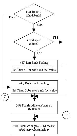
Dan, from looking at your flow diagrams and comments in the spark interrupt code am I right in thinking the following:The road speed limit is only checked before firing the odd side injectors and therefore when over the speed limit only the odd side injectors are stopped firing. Also, am I right in thinking the code then branches down to toggle the next bank to fire? As the road speed limit is not checked when firing the even bank does that mean only the odd bank is shut off when over the speed limit?
stevesprint said:
Dan, from looking at your flow diagrams and comments in the spark interrupt code am I right in thinking the following:
The road speed limit is only checked before firing the odd side injectors and therefore when over the speed limit only the odd side injectors are stopped firing. Also, am I right in thinking the code then branches down to toggle the next bank to fire? As the road speed limit is not checked when firing the even bank does that mean only the odd bank is shut off when over the speed limit?
Steve, yes, one bank stops firing at the limit. The opposite bank is not fired instead, if that was your question. That bank waits for its normal turn in the sequence. As Mark Adams pointed out, this approach is an effective soft-cut and takes very little processing. The down side is all those VSS state samples along the way.The road speed limit is only checked before firing the odd side injectors and therefore when over the speed limit only the odd side injectors are stopped firing. Also, am I right in thinking the code then branches down to toggle the next bank to fire? As the road speed limit is not checked when firing the even bank does that mean only the odd bank is shut off when over the speed limit?
danbourassa said:
Steve, yes, one bank stops firing at the limit. The opposite bank is not fired instead, if that was your question. That bank waits for its normal turn in the sequence.
Dan sorry, that’s exactly what I meant “toggles and then waits for its normal turn in the sequence”. Thanks.This means the soft-cut effect is a result of the code deliberately running the engine on one bank of injectors at the road speed limit and from personal experience thats what it feels like, the engine is running on 4 cylinders. MA is certainly right about the woolliness in determining the live road speed as I've noticed the limiter kicking in at different road speeds depending on the rate of acceleration and what gear I was in.
Edited by stevesprint on Tuesday 13th May 20:54
Dan,
When I started studying the full data structure and you comments in the code I noticed in the main loop that you say the high RPM ADC mux table is heavily loaded with extra road speed measurements. Therefore my first thought was would removing all the extra road speed measurements from the high RPM ADC mux table stop the road speed measurements above 4185 RPM? If so would that remove the road speed limiter above 4185 RPM and reduce the load on the processor. I’m sure you remember what happened the last time I change a mux table, lol, but at least we learnt something.
BUT!! More recently I’ve noticed in your RoadSpeed V2 comments that the main ADC road speed service routine is called from the main loop and I quote “Oddly, the 8-bit value measured at channel 7 (the VSS signal) by the ADC prior to entering this routine is not used” and I see you explanation why.
Does this mean the extra road speed samples in the high RPM mux table are wasting time, at high RPM, testing for idle and faults and not actually measuring the road speed?
In roadspeed asm you say the road speed calculation route (comparator test) is call numerous times from the spark interrupt. So does this mean the road speed is actually calculated via calls from the spark interrupt and not via the main loop mux table which I think answers my first question. Removing the extra road speed samples wouldn’t remove the road speed limiter above 4185 RPM as the road speed is calculated in the spark interrupt.
I’m now starting to question the benefit of the high RPM Mux table.
Cheers
Steve
Gassing Station | Griffith | Top of Page | What's New | My Stuff