Instructions to change fuel maps on 14CUX Griffith, Chimaera
Discussion


stevesprint said:
Also, should I be using a Hall effect speed sensor as my Caerbont EMP34-1 sensor is amplified inductive and outputs a true square wave. I’ve been informed the LT77 sensor is an open collector with a transistor amp, what ever that means.
Dan,
In the winter I'm now seriously considering installing the same Hamlin sensor as yours, therefore which version do you have, the 00 or the AP?
55075-00-02-A (Digital Output)
http://uk.farnell.com/hamlin/55075-00-02-a/sensor-...
55075-AP-02-A (Analogue Pulse)
http://uk.farnell.com/hamlin/55075-ap-02-a/sensor-...
It's probably a good idea to borrow Mark's data logger and check the waveform. If the waveform is 0V/12V which is what my old LT77 produced, then the ECU should be happy (not sure about the speedometer). I use the Hamlin 00 part (digital output) and I generally like the idea of the Hall effect technology because the signal doesn't fade as the wheel slows down. However, if your Caerbont's signal is internally processed and outputs a square wave, I think it should work.Dan,
In the winter I'm now seriously considering installing the same Hamlin sensor as yours, therefore which version do you have, the 00 or the AP?
55075-00-02-A (Digital Output)
http://uk.farnell.com/hamlin/55075-00-02-a/sensor-...
55075-AP-02-A (Analogue Pulse)
http://uk.farnell.com/hamlin/55075-ap-02-a/sensor-...
Here's one other thing to think about. The VSS comparator threshold is set to $C8 (in roadSpeed.asm). This level will not work if the waveform is degraded and you may have to reduce the value. My bench setup uses a TTL level VSS (0V/4V) which would not initially work. I had to reduce the threshold to somewhere between $35 and $4C to get it to trigger. In code version 3, this threshold is no longer hard-coded but is defined in the data file as follows:
vssStateThreshold = $C8 ; normally $C8 (reduce for bench testing, 1.0V = $35, 1.5V = $4C)
Dan, Your a total and utter genius.
I've changed my comparator/ vssStateThreshold to hex 86 in RoadSpeed.asm Version 2 as 86 is between the standard figure and your bench figure (lucky guess) and now my RG speedo finally works. Previously my RG speedo was fairly accurate up to 40mph but after 40mph it use to start decreasing as the road speed increased. But now the RG speedo keeps increasing as the road speed increases past 40mph.
Its interesting how my dash speedo has always been spot on, but so it should as my speedo and sensor are designed to work together. Plus I was informed they wouldn't upset the 14CUX, and they didn't.
My RoverGauge speedo calibration still isn't perfect at 70mph but at least its now usable and in the winter I could correct the calibration with a different crown wheel.
Dan, I can't thank you enough.
Steve
Mark,
That's the best offer I've had all year especially if you mean your logger you developed that piggy backs straight onto the 14CUX as it must be very precious.
Although my RG speedo is now working I would still appreciated the opportunity to borrow a logger. I would be to scared to borrow your piggy back one so I've made the road speed signal cables easily accessible though an air vent.
If you make it to the TVR Berkshire pub met this Tuesday we could have a quick logging session down the dual carriageway opposite the pub, any excuse for a blast, lol. I'm keen to learn, test and compare my steering speed sensor with my speedo sensor as my steering sensor is halls effect, but doesn't work with RG unless its output is simultaneously connected to the steering ECU.
There is no pressure to meet at the pub as my RoverGauge speedo now works and its now purely self-indulgence.
Thanks for the offer
Steve
stevesprint said:
Dan, Your a total and utter genius.
I had to show this to my wife since she doesn't always share your feelings on this. Maybe if she drove a 14CUX powered vehicle??stevesprint said:
My RoverGauge speedo calibration still isn't perfect at 70mph but at least its now usable and in the winter I could correct the calibration with a different crown wheel.
If the dash speedometer is working OK, it may make more sense to make the RG correction in software. Dave had an easy fix since his was off by a factor of two, but scaling by an odd amount is not difficult.blitzracing said:
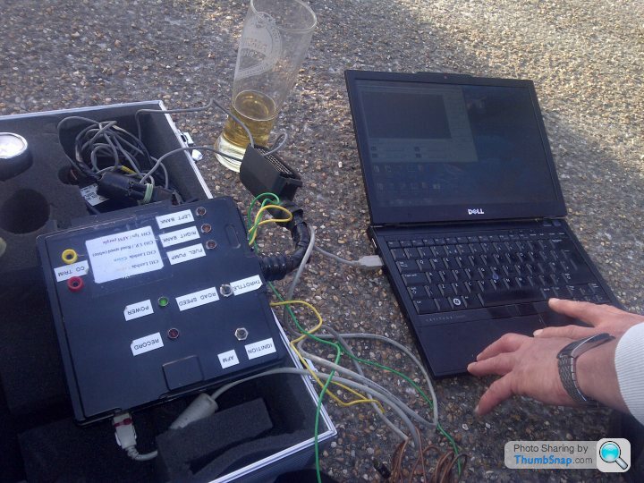
Hi Steve- I can lend you the data logger for the ECU I have so you can check the waveform from the speed sensor to see if its switching correctly. It will save a lot of speculation.
It’s not often you see a homemade 14CUX data logger in a pub car park, only at a TVR meeting. Mark, it’s mine now and you’re not getting it back.
danbourassa said:
I had to show this to my wife since she doesn't always share your feelings on this. Maybe if she drove a 14CUX powered vehicle??
Dan, Please tell your wife you’re only working on the 14CUX for her benefit because you both might be invited to stay with us if you ever visit the UK, but only if you’re allowed to continue.danbourassa said:
If the dash speedometer is working OK, it may make more sense to make the RG correction in software. Dave had an easy fix since his was off by a factor of two, but scaling by an odd amount is not difficult.
Dan, It would be useful one day to learn how to recalibrate the 14CUX road speed but seriously it can wait until the winter as I can easily do it in excel. I guess Colin could even add a recalibration feature to RoverGauge.stevesprint said:
blitzracing said:
Hi Steve- I can lend you the data logger for the ECU I have so you can check the waveform from the speed sensor to see if its switching correctly. It will save a lot of speculation.
It’s not often you see a homemade 14CUX data logger in a pub car park, only at a TVR meeting. Mark, it’s mine now and you’re not getting it back.What did the speed sensor waveforms look like in the end?
danbourassa said:
If the dash speedometer is working OK, it may make more sense to make the RG correction in software. Dave had an easy fix since his was off by a factor of two, but scaling by an odd amount is not difficult.
I did this fix in a R2422.Been away from 14CUX for awhile, must get back on the pace.
davep said:
stevesprint said:
blitzracing said:
Hi Steve- I can lend you the data logger for the ECU I have so you can check the waveform from the speed sensor to see if its switching correctly. It will save a lot of speculation.
It’s not often you see a homemade 14CUX data logger in a pub car park, only at a TVR meeting. Mark, it’s mine now and you’re not getting it back.Dave,
I’m starting to regret borrowing Marks data logger as I can now see how pants my road speed sensor is and I can’t understand how my dash speedo is so accurate. It’s also amazing reducing the comparator improved RoverGauge speedo above 40mph which now reads 50mph at 60mph instead of 25mph but more importantly its linear now.
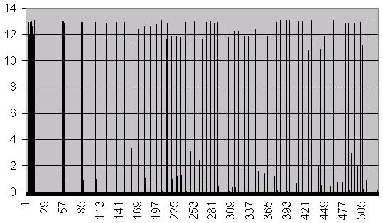
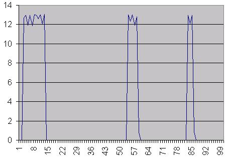
0 to 15mph (sample rate of 0.01s)
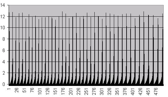
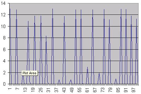
Steady 60mph (same sample rate of 0.01s)
Mark,
As both logs are at the same sample rate I’m not convinced the 60mph log looks correct, what would you expect at 60mph.
I’m honoured you've trusted me with you crown jewels, thanks.
Dan,
FactBV on PHs is considering installing a T5 in his precat and has asked me off air what’s the best speed sensor to use, therefore is it safe to recommend your Hamlin sensor. He realises he’ll also have to change his dash speedo.
I’m starting to regret borrowing Marks data logger as I can now see how pants my road speed sensor is and I can’t understand how my dash speedo is so accurate. It’s also amazing reducing the comparator improved RoverGauge speedo above 40mph which now reads 50mph at 60mph instead of 25mph but more importantly its linear now.
0 to 15mph (sample rate of 0.01s)
Steady 60mph (same sample rate of 0.01s)
Mark,
As both logs are at the same sample rate I’m not convinced the 60mph log looks correct, what would you expect at 60mph.
I’m honoured you've trusted me with you crown jewels, thanks.
Dan,
FactBV on PHs is considering installing a T5 in his precat and has asked me off air what’s the best speed sensor to use, therefore is it safe to recommend your Hamlin sensor. He realises he’ll also have to change his dash speedo.
The scan rate of the logger is relatively slow, so you dont get a true reading of the signal as speeds up- it tends to put a spike on the leading edge as the pulse rises- in the case of the speedo sensor simply make sure you get a good clean 12v square wave (or what ever the mark space ratio is for your sensor)- you can do this as slow as the car can move to keep the frequency low.
blitzracing said:
The scan rate of the logger is relatively slow, so you dont get a true reading of the signal as speeds up- it tends to put a spike on the leading edge as the pulse rises- in the case of the speedo sensor simply make sure you get a good clean 12v square wave (or what ever the mark space ratio is for your sensor)- you can do this as slow as the car can move to keep the frequency low.
Mark, Here’s the data for the first 9 pulses in the first graph at slow speed. You can see from the first graph the output starts off OK but gaps appear as the voltage randomly drops as the frequency increases. This explains why the RoverGauge Speedo isn't very accurate, I might try one of Dan's Hamlin sensors in the winter.
13.41  0               14.21  0               14.73  0
13.42  12.706          14.22  12.941          14.74  12.941
13.43  12.941          14.23  12.059          14.75  12.882
13.44  11.941          14.24  12.941          14.76  0
13.45  12.941          14.25  0.882
13.46  11.882          14.26  0               14.85  0
13.47  13                                     14.86  12.824
13.48  12.941          14.41  0               14.87  12.941
13.49  12.588          14.42  12              14.88  0
13.5   13              14.43  11.765
13.51  12              14.44  12.941          14.96  0
13.52  13.059          14.45  1               14.97  11.529
13.53  0               14.46  0               14.98  3.353
                                              14.99  0
13.92  0               14.58  0
13.93  13              14.59  12.882          15.06  0
13.94  12.353          14.6   11.824          15.07  12.353
13.95  13              14.61  12.882          15.08  12.353
13.96  11.941          14.62  0               15.09  0
13.97  12.824
13.98  0.824
13.99  0
stevesprint said:
Dan,
FactBV on PHs is considering installing a T5 in his precat and has asked me off air what’s the best speed sensor to use, therefore is it safe to recommend your Hamlin sensor. He realises he’ll also have to change his dash speedo.
I think it's safe to recommend it. It's not expensive, so if, for some reason, it doesn't work for him, it won't be a disaster. The output waveform looks very much like a square wave (similar to the LT77 except for frequency).FactBV on PHs is considering installing a T5 in his precat and has asked me off air what’s the best speed sensor to use, therefore is it safe to recommend your Hamlin sensor. He realises he’ll also have to change his dash speedo.
This brings me to a question about the graphs. Why do they show spikes rather than a square wave? If the ECU is seeing spikes, they could be easy to miss by the sampling code. The Hall effect sensor seems to electrically duplicate the profile of the crown wheel, which, it seems to me, is what you would want. A square wave close to 50/50 duty cycle gives the best chance for capturing each state transition.
I think thats a function of the logger- its designed to read analogue voltage changes over a period- so its fine for TPS, lambda and AFM etc. It seems to produce the glitches where you have very fast changes in signal levels on the leading edge- ie primary ignition and speed. You should get a decent reading running the car at low speed to show the square wave, but I would not rely on it at higher frequencies as the sample rate is slow. It really needs an osciloscope for the faster stuff.
Just in case anyone finds it interesting or useful, here's some info about what we did to deal with the road speed signal while doing the T5 swap on Dan's Griffith:
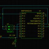
I think the LT77's output shaft sensor was producing 5 pulses per every 4 rotations, but the new tone wheel with the T5 installation would produce something like 17 pulses/rotation. I decided to build a small programmable 12V frequency divider so that the new high-frequency pulse train could be stepped down to the equivalent LT77 rate. I went with a TI MSP430 micro because that made it easy to change the software for different behavior if required. (And buying MSP430s doesn't exactly break the bank.)
Note that this is very much a prototype. I can't guarantee that it'll work for everyone, but it's certainly a starting point for those that want to adapt the fast waveform of the multi-tooth tone wheel to the instruments in a car originally fitted with the LT77.
Here's the schematic:
and here's the MSP430 code:
http://pastebin.com/5FGMtAmB
cmb said:
Just in case anyone finds it interesting or useful, here's some info about what we did to deal with the road speed signal while doing the T5 swap on Dan's Griffith:
Colin,Thanks for sharing your road speed set-up with us all, I've been secretly dying to know how you interfaced to the dash speedo. Is that all the code is required plus the header files, you two are very clever. If Mark starts building them I'm sure we'll see more T5 implants as retaining the dash speedo seems to be the biggest hurdle. It’s interesting you had 5 pulses per 4 prop rotations as I use to have about 3 pulses per 1 prop rotation with the LT77. Your 17 pulses/prop rotation sounds about right as the crown wheels are available with 16, 17 or 18 teeth. I'm extremely lucky as I have a very kind and clever friend in the USA, that you may know, who might show me one day how to recalibrate the ECU speedo.
danbourassa said:
I think it's safe to recommend it. It's not expensive, so if, for some reason, it doesn't work for him, it won't be a disaster. The output waveform looks very much like a square wave (similar to the LT77 except for frequency).
Dan, Thanks, as the Hamlin sensor its not expensive I may try fitting one in the winter so I'll have separate sensors for the dash speedo and ECU.
danbourassa said:
This brings me to a question about the graphs. Why do they show spikes rather than a square wave? If the ECU is seeing spikes, they could be easy to miss by the sampling code. The Hall effect sensor seems to electrically duplicate the profile of the crown wheel, which, it seems to me, is what you would want. A square wave close to 50/50 duty cycle gives the best chance for capturing each state transition.
I showed the speed sensor as a bar graph because the bar represents the sudden 0v - 12v - 0v clearer, where as the line graph show misleading glitches that Mark mentioned.This line graph is for the 1st second of the same data above and you can just about see the glitches that are not in the data.
In this second line graph you can see at speed my sensor randomly drops the output voltage, also the glitches are more obvious.
Dan, SteveSprint, I’ve been looking at when and how LimpHomeMap (Map 0) is selected mainly to determine if any EMS condition other than tune resistor value out of range can cause its selection. I’ve gone through the ASM files at length and I’m unclear as to how the fuelMapPtr value is set for #fuelMap0 in ADC Routine, Channel 10. The only way, it seems to me, is that it is selected by default. Any thoughts?
Dave, you may be correct about this. As far as I can tell, even if something as essential as the MAF sensor fails, it does not force the limp home map. Instead, the ECU substitutes a value based on TPS position and coolant temperature and continues with the current fuel map (and you get a MAF related fault code, of course). Then why have the limp home map at all? There is still a lot I don't understand about this. Map 0 is considered a closed loop map by the ECU and the code path is the same as maps 4 and 5. But what if you don't have O2 sensors? Does this mean that fault code 21 is soon followed by fault codes for the O2 sensors? It seems to me that map 0 is unnecessary and if code just defaulted to an existing closed loop map (out of concern for the possible presence of catalytic converters) it would be just fine.
If only the tune resistor can force limp home mode, then its fault code 21 is one that most NAS vehicles can never see. Since at least 1992, and possibly earlier, NAS vehicles have the fuel map locked to map 5 and the resistor is ignored. There must have been enough sales volume in North America by then that a number of things regarding the 14CUX became unique for NAS. Although the blue 2-way tune resistor connector was still in the wiring harness (at least initially) the terminal was missing from the 40-pin connector. This, I imagine, had to make the wiring harness NAS specific. Also, even though the ECU software still treated the map locking as a settable option in the data portion of the code, a fixed mask value disables code 21. Again, this points to NAS specific code.
You have probably figured this out already but the fuel map number is stored in three separate places in RAM.
fuelMapNumber (X202C) -       This is the main working value. It's used to make code path decisions (for example open vs. closed loop)
                              and used to set the address pointer when loading data from the fuel map data structure.

fuelMapNumberBackup (X0050) - This is in the RAM area that is preserved by the battery. It exists mostly to complicate your life. This
                              value is compared with the above 'fuelMapNumber' and you get DTC 21 if they don't match. This is why you
                              can't change maps on the fly without getting the fault code. This is easy to defeat, by the way.

(mirrored value X0050)-       All the battery preserved values are also saved in a second area in RAM. They are periodically compared
                              and, if there is a mismatch, the main values are set back to defaults. I think this mirroring was done as
                              a sort of fail safe but, I'm convinced, it just makes matters worse.
Edited by danbourassa on Wednesday 2nd July 18:44
You know what I'm going to ask now, don't you? What if I take the NAS approach and lockout map selection to Map 2, do you foresee any problems in the related code path? I'm looking at this approach as a solution to the 'normally run in open loop with Map 2, but in the event of a tune resistor fault run in closed loop with Map 0 on a non-cat car' conundrum.
I think this should work just fine. Version 3 has a fuel map force option built in.
The top two lines are in the data file and remainder is at the top of tuneResistor.asm. Instead of checking the lock value, the code loads the defined force value over the just measured tune resistor (in register A) and continues normally. This should never fail since the measured resistor value is now irrelevant.
Code checks from the lowest value up, as follows:
Less than $0A = fault (map 0)
Less than $3D = map 1
Less than $63 = map 2
Less than $80 = map 3
Less than $B9 = map 4
Less than $F6 = map 5
Else fault (map 0)
The top two lines are in the data file and remainder is at the top of tuneResistor.asm. Instead of checking the lock value, the code loads the defined force value over the just measured tune resistor (in register A) and continues normally. This should never fail since the measured resistor value is now irrelevant.
FORCE_FUEL_MAP = 0  ; set to 1 to activate fuel map override
FUEL_MAP_VALUE  EQU  $70 ; $70 forces map 3 (change this as required)


IF FORCE_FUEL_MAP

adcRoutine10    ldaa    #FUEL_MAP_VALUE
                bra     .LD552

ELSE
adcRoutine10    ldab    fuelMapLock             ; load fuel map lock value
                beq     .LD552                  ; branch ahead if zero
ENDC
Code checks from the lowest value up, as follows:
Less than $0A = fault (map 0)
Less than $3D = map 1
Less than $63 = map 2
Less than $80 = map 3
Less than $B9 = map 4
Less than $F6 = map 5
Else fault (map 0)
Gassing Station | Griffith | Top of Page | What's New | My Stuff