What's this spare connector behind the alternator?
Discussion


Hi All,
Can someone help identify this connector located behind the alternator? One of the wires is black/purple.
The connector comes live when the ignition is turned on and if I jump the connector both radiator fans start.
Could this be related to a car with A/C fitted (mine doesn't).
I'm wondering if this connector would be suitable for installing a fan override switch as this summer caught in traffic the car suffered what I believe was fuel evaporation in the fuel rail... The fans kick in at 90 degrees as expected so getting the fans running a bit earlier might help manage the issue.
Thanks in advance for the assistance.
The easiest way i found was to identify the green/pink wire which lives behind the radio in a white coloured connector and connect this to ground via a switch. I used the dash light on/off switch for this purpose and just disconnected it and linked the wires as i didnt use it at all.
I wouldnt bridge those connections until someone can confirm their location in the circuit, i cant personally as they are not on my diagrams.
I wouldnt bridge those connections until someone can confirm their location in the circuit, i cant personally as they are not on my diagrams.
Belle427 said:
The easiest way i found was to identify the green/pink wire which lives behind the radio in a white coloured connector and connect this to ground via a switch. I used the dash light on/off switch for this purpose and just disconnected it and linked the wires as i didnt use it at all.
I wouldnt bridge those connections until someone can confirm their location in the circuit, i cant personally as they are not on my diagrams.
Thanks for that. I'll have a look at the weekend... I wouldnt bridge those connections until someone can confirm their location in the circuit, i cant personally as they are not on my diagrams.
The connector is redundant on TVRs. The 14CUX ECU remains powered for approximately five seconds after ignition is switched to OFF. During this time, it monitors under-hood temperatures through the engine fuel temperature sensor. If measured temperatures exceed 70° C (150° F), the ECU grounds a Land Rover fan control module via the BP wire and the connector in question, allowing condenser fans to run for ten minutes. HTH
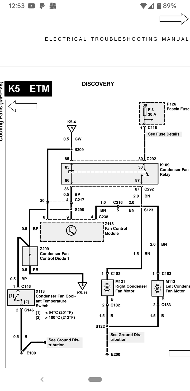
It's a bit long winded but here's how the cooling fans work on the donor car for the TVR engine loom, refer to figure below:
Condenser Fan Operation (MFI–V8)
The Condenser Fans Motors (M113, M121) on vehicles equipped with MFI–V8 engines operate when any of the following conditions occur:
1. Coolant temperature exceeds 100 deg C (212 deg F).
2. The air conditioning system is operating.
3. The Engine Control Module (ECM) (Z132)
determines that fuel temperature exceeds 70 deg C and coolant temperature exceeds 110 deg C after engine shutdown. When this occurs, the fans are turned on for approximately 10 minutes after the engine is shut off.
Operation with High Coolant Temperature (MFI–V8)
When the Ignition Switch (X134) is in position II, battery voltage is applied to the Ignition Load Relay (K127). The relay is energized, applying battery voltage to the Condenser Fan Relay (K109) and the Fan Control Module (Z118). If the coolant temperature exceeds 100 deg C (212 deg F), the Condenser Fan Coolant Temperature Switch (X113) closes and energizes the Condenser Fan Relay (K109), via C146 the connector in question, by applying ground to the relay’s coil. When the relay is energized, voltage from fuse F3 is applied to the Condenser Fan Motors (M113, M121).
Fan Operation with A/C (MFI–V8)
With the Ignition Switch (X134) in position II, battery voltage is applied to the Ignition Load Relay (K127). The relay is energized, applying battery voltage to the Condenser Fan Relay (K109). When the Front A/C Switch (X225) is turned on and the Front Fan Speed Switch (X247) is turned to positions I, II, II, or IV, ground is applied to terminal 86 of the Condenser Fan Relay. The relay energizes, applying battery voltage from fuse F3 to the Condenser Fan Motors (M113, M121).
Operation with the Engine Off (MFI–V8)
The Engine Control Module (Z132) monitors fuel temperature and coolant temperature through sensors. When the ECM determines that fuel temperature is above 70 deg C and coolant temperature exceeds 110 deg C after engine shutdown, the ECM will command fan operation for approximately 10 minutes. The ECM turns on the fans by momentarily grounding the Fan Control Module (Z118) through the BG wire. When the timer unit is grounded, it starts a solid state timer and begins to apply ground from its terminal 9 to the Condenser Fan Relay (K109) through the BP wire. With the Condenser Fan Relay energized, voltage from fuse F3 is applied to the Condenser Fan Motors (M113, M121).
Note: On TVRs, as standard, cooling fan operation is controlled by a dedicated Otter switch, so none of the above applies. However, you have switched your car's cooling fans on by bridging C146, which suggests that relay K109 is in circuit?
Edited by davep on Wednesday 17th April 14:26
DVR V8 said:
Hi Adrian before retiring spent 35 years at Rolls Royce and Bentley a electrical engineer so had a friend at Lucas/Rists who got me the main build harness drawing for the Rover V8 EFI 14CUX. It could be used to manufacture a new harness on a peg board. Regards.
Thanks ... for a moment I thought there were that version schematics for the Griff/Chim (which there are for Cerbera onwards). Then I could not see the OP's twin plug within those drawings. I think it is mentioned within the post the override would be taken from the Otter switch simply by piggy backing it. A@
Adrian@ said:
DVR V8 said:
Hi Adrian before retiring spent 35 years at Rolls Royce and Bentley a electrical engineer so had a friend at Lucas/Rists who got me the main build harness drawing for the Rover V8 EFI 14CUX. It could be used to manufacture a new harness on a peg board. Regards.
Thanks ... for a moment I thought there were that version schematics for the Griff/Chim (which there are for Cerbera onwards). Then I could not see the OP's twin plug within those drawings. I think it is mentioned within the post the override would be taken from the Otter switch simply by piggy backing it. A@
Gassing Station | Chimaera | Top of Page | What's New | My Stuff