Throttle bodies and forced induction
Discussion


DaveL485 said:
Thankyou!

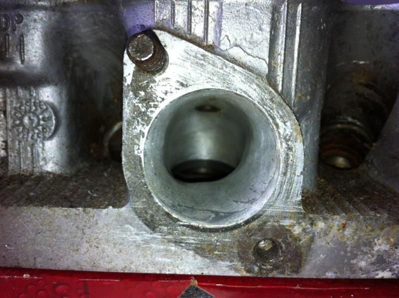
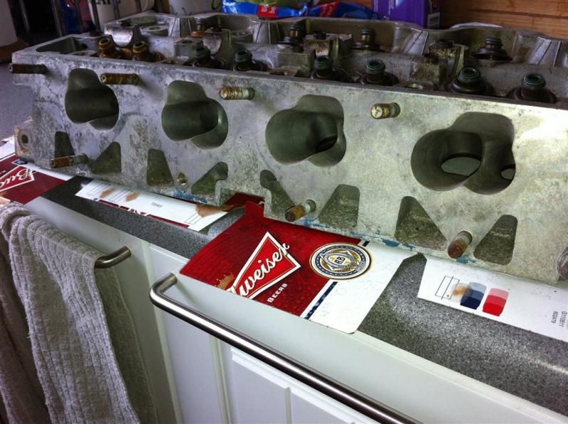
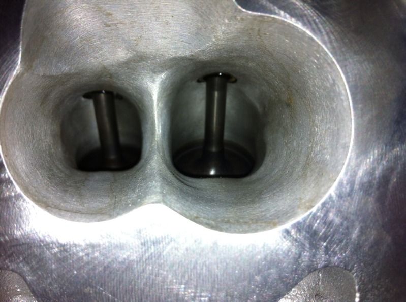
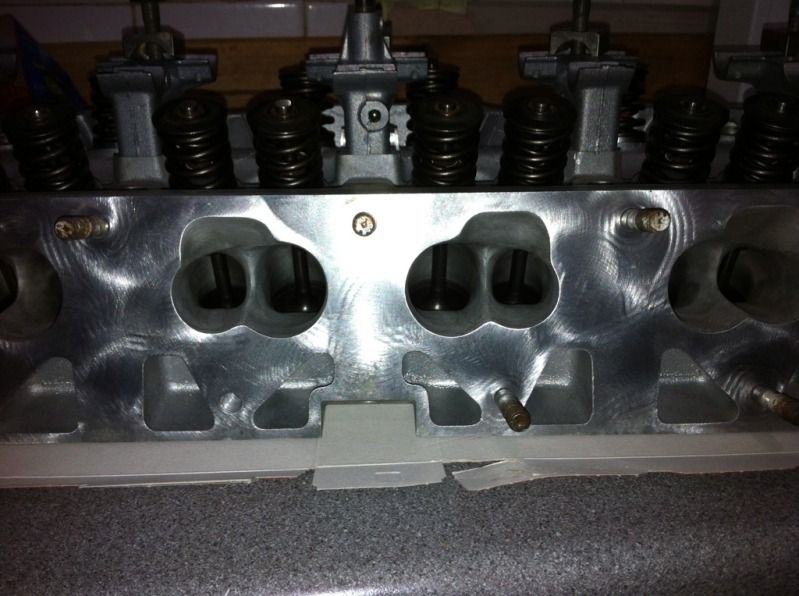
Anyway, this is what i'm feeding. Ports at their widest points are 35mm by 55mm, valves are ~31mm and ~35mm.
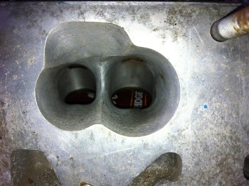
Looks like quite a decent porting job, I'm noting the D shape over the SSR and PQ design. Any reason for the sharp step between the injector spray housing and general port area?Anyway, this is what i'm feeding. Ports at their widest points are 35mm by 55mm, valves are ~31mm and ~35mm.
I don't think it's accurate to quote a port size like that, more a case of cross sectional area (CSA)?
Really looking forward to seeing some results for this one!
Edited by Evoluzione on Sunday 8th April 15:15
Edited by Evoluzione on Tuesday 1st January 16:49
Evoluzione said:
What is a 'J-Series Renault 2.0' ?
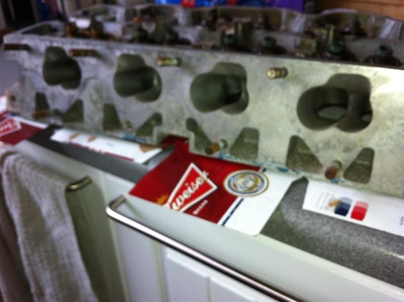
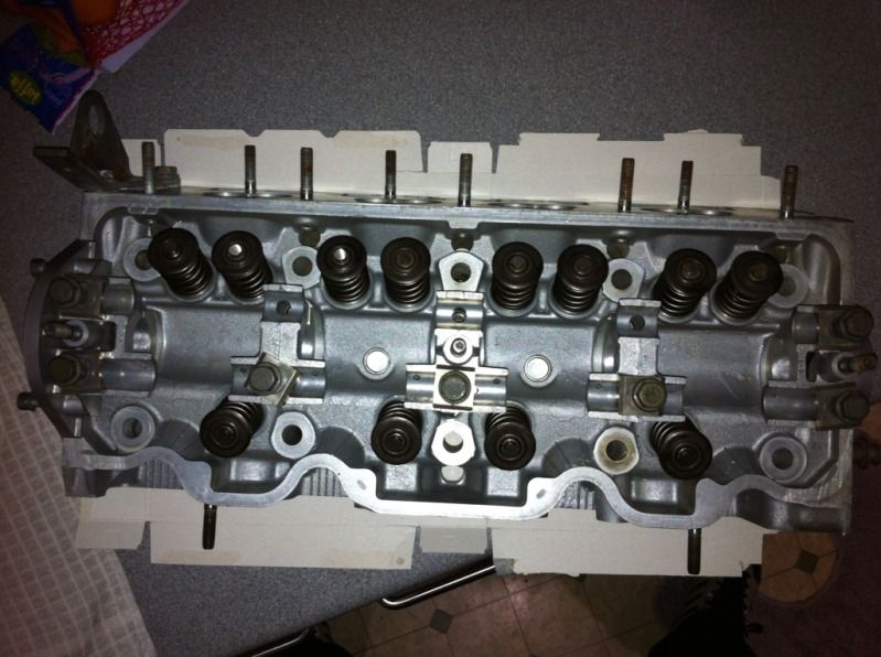
The engine I started with was a J7R 752 Renault 21 Turbo, 8 valve SOHC engine. 175bhp, 199lb/ft out the box. The head i'm working with now is from the Renault 21 TXi 12 valve (Normally aspirated)....i'm using the 12v NA head on the 8v Turbo block.Edited by Evoluzione on Sunday 8th April 12:57
Wiki said:
Main article: Douvrin engine
The J family (also referred to as the Douvrin engine) was an all-aluminum overhead camshaft inline-4 overhead camshaft design jointly developed with PSA. Introduced in 1977, it was phased out in 1996 by the F series.
J5R/J6R/J7R: 1995 cc
J6T/J7T: 2165 cc
J8S: 2068 cc
I did toy with stroking it for the 2165cc too, but want to rev it higher so stuck with the 2.0 crank.The J family (also referred to as the Douvrin engine) was an all-aluminum overhead camshaft inline-4 overhead camshaft design jointly developed with PSA. Introduced in 1977, it was phased out in 1996 by the F series.
J5R/J6R/J7R: 1995 cc
J6T/J7T: 2165 cc
J8S: 2068 cc
Evoluzione said:
Looks like quite a decent porting job, I'm noting the D shape over the SSR and Polyquad design. Any reason for the sharp step between the injector spray housing and general port area?
I don't think it's accurate to quote a port size like that, more a case of cross sectional area (CSA)?
Really looking forward to seeing some results for this one!
Thanks, i'll add some more detail if you're interested then I don't think it's accurate to quote a port size like that, more a case of cross sectional area (CSA)?
Really looking forward to seeing some results for this one!
Edited by Evoluzione on Sunday 8th April 15:15

It's for this:
Currently factory 8v internals, mild hybrid turbo, 38mm external wastegate, 3" exhaust, air filter, 3" FMIC.
OE Management, fuelling other than a swirl pot and 18psi saw it about 240bhp-ish.
Current development for the engine in a nutshell is:
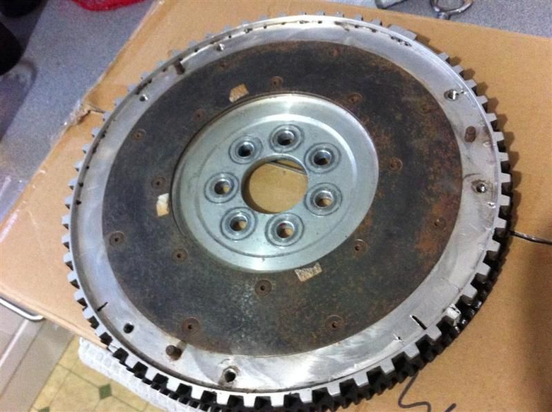
Lightened, balanced & knife edged crank.
Lightened & balanced rods.
Bespoke 24T Billet steel cylinder liners with wire-ringing, rounded edges on cyl 1&4.
Bespoke forged pistons with Ti-Ni coated rings.
12v cylinder head, modified ports as pictured, cut back stems and manifolds matched (although a bespoke inlet is being made).
044 fuel pumps, 8 injectors (not decided on size yet but around 1000cc/min total), direct port nitrous (wet kit) with independent fuel pump likely.
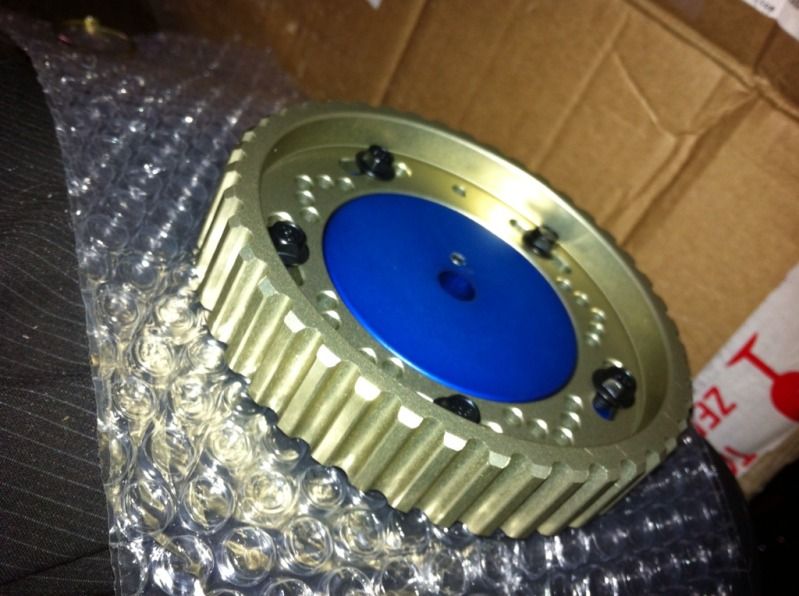
Billet steel cam, Vernier style pulley.
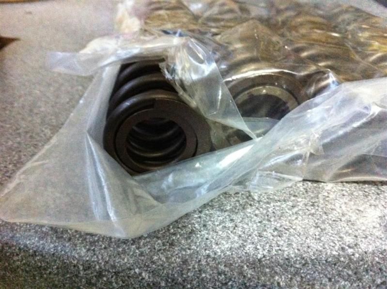
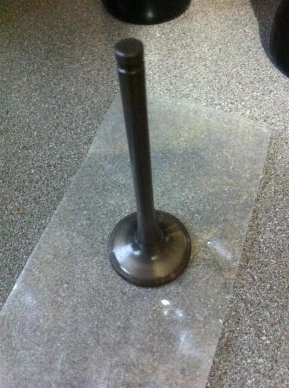
Nimonic 80A superalloy (I love that word) exhaust valves, double springs, bespoke valve spring seats and retainers.
Turbo undecided but using a .50ar front on a T3 core with a .48 back to run it in. Considering something like a GTX3076R with a .70ar front for the final build.
Standalone management with all the bells and whistles functionality wise, running from a 36-1 trigger on the crank. Currently batch fire injection though, might go sequential.
It's taken me seven years to get this far, because
1)Nothing is off-the-shelf for the engine, nobody makes anything really
2)It's f
 king expensive and i'm not particularly rich. Quite the opposite in fact.
The sharp step between the injector spray housing and general port area....erm....thats the way they made it. So no!
Edited by DaveL485 on Monday 9th April 11:52

stevieturbo said:
As you're going to use 2 inj per cylinder there really isnt any need to go sequential. It can be a hassle sorting a cam trigger sometimes.
As for turbos, Precision make a huge range of turbos that work very well, and are keenly priced.
Thanks for the tip on the Turbo....I never bought new before, always rebuilt my own too. Nice to have a recommendation to work from. eBay is full of cheap copies its hard to see whats what!As for turbos, Precision make a huge range of turbos that work very well, and are keenly priced.
From reading RedVictor's writeup, seems Owens Developments are Precision dealers in the UK.
Or there is a local one near me who is pretty good to deal with who I'm sure would be happy to post etc.
Although you wont go far wrong with one of the new billet Garrett units either.
Precision sell them based on approx power capability too which is handy for sizing. Something like a ballbearing version of this would be good
http://www.precisionturbo.net/Street-and-Race/ss/4...


Max_Torque said:
Ok, lets apply some sience to this "black art" shall we!
Air, it's actually quite heavy, and the more you cool or compress it, the heavier (well technically the more dense) it gets.
So lets first calculate the density of some air:
take the air around us now, say it's at standard atmospheric conditions (1bar abs, 25degC):
Firstly, you need to know a charactisitics of air, its "Gas Constant". Now this has some slightly confusing units of J/KgK (Joules per KilogramKelvin) but don't worry too much about that for now. All you need to know is that for "normal air" it is 287 J/KgK.
We also need the air temperature in DegC (25 in this case) and the air pressure (in kPa absolute terms)
So, for 25degC and 100kPa abs, the density of air in Kg per cubic meter (Kg/m3) is:
Density = (pressure x 1000 ) / (Gas Const x (air temp + 273))
so for 25degC and 1barAbs that is equal to 1.17Kg/m3
Now let blow some boost, say 1bar gauge, so thats 2bar Abs (or 200kPa abs), the new density is 2.34kG/m3. And as expected, double the pressure, and you double the density.
So why do we care about density so much? Well it is a measure of how much energy a substance contains when moving at a certain speed. Dense things are heavy (for a given fixed volume) so require more energy to accelerate of decellerate.
Dynamic Pressure is a measure of the amount of energy stored in a moving fluid, it's the bit that can be "lost". Static pressure is never lost (unless some of you fluid escapes it's confinement).
So lets calculate the dynamic pressure in a tube!
Lets take a 60mm internal diameter tube, and convientently ignore any skin effects (assume all the area is used for flow, which it isn't, but ignore that for now). So we need the area of said tube (easy that one, (Pi x (Radius squared)). So for our 60mm tube, that's 2827.4 mm2, or 0.0028274 m2.
Now we need to know how much air is flowing down said tube in a given time. This is usually quoted as a volumetric flow in cubic meters per second (m3/s). You will need to work this out for your application, although generally, taking the engine capacity in litres divided by two and multiply by the engine speed in revs per second (for a four stroke engine) and assuming 100% volumetric efficiency will see you to a figure for volumetric flow fairly closely.
For example, lets take a 2.0litre engine at WOT at 6000rpm:
Per rev 1 litre of air is ingested (four stroke remember so only 2 cyls fire per rev). 6000rpm is 100 revs per sec, so we now have 100litres per second. As there are 1000litres in a cubic meter, this is 0.1m3/sec
So how fast does 0.1m3/s move down a pipe or area 0.0028274m2 ??
We want m/s, so if we divide m3/s by m2, we are left with just m/s. So 0.1 / 0.0028274 is 35.4 m/s, or just a smidge over 75mph !
Now finaly, we get to calc the dynamic pressure:
Dynamic pressure (in kPa) = ((0.5 x Density(Kg/m3) x Velocity(m/s) )squared)/1000
in this case that's = 1.71kPa.
What does this mean? Well, if you were to deccelerate all that air to a stop, without "recovering" any of the dynamic pressure, you stand to loose 1.71kPa.
Generally, it is good to keep the dynamic component below 1kPa, in this case that would take a tube of 68.5mm internal diameter.
I'll leave the discussions of "effective hydraulic diameter" to another day, or really "how much of the geometric area of my tube is actually being used by the airflow........." ;-)
Garrett uses the internal ducting velocity to determine size. In general they want to see about 250 fps. And, going from a 400+ fps setup (2.5" pipes on a 600 hp build) to a more decent 3" setup often nets you some quicker spool and a more responsive engine. Air, it's actually quite heavy, and the more you cool or compress it, the heavier (well technically the more dense) it gets.
So lets first calculate the density of some air:
take the air around us now, say it's at standard atmospheric conditions (1bar abs, 25degC):
Firstly, you need to know a charactisitics of air, its "Gas Constant". Now this has some slightly confusing units of J/KgK (Joules per KilogramKelvin) but don't worry too much about that for now. All you need to know is that for "normal air" it is 287 J/KgK.
We also need the air temperature in DegC (25 in this case) and the air pressure (in kPa absolute terms)
So, for 25degC and 100kPa abs, the density of air in Kg per cubic meter (Kg/m3) is:
Density = (pressure x 1000 ) / (Gas Const x (air temp + 273))
so for 25degC and 1barAbs that is equal to 1.17Kg/m3
Now let blow some boost, say 1bar gauge, so thats 2bar Abs (or 200kPa abs), the new density is 2.34kG/m3. And as expected, double the pressure, and you double the density.
So why do we care about density so much? Well it is a measure of how much energy a substance contains when moving at a certain speed. Dense things are heavy (for a given fixed volume) so require more energy to accelerate of decellerate.
Dynamic Pressure is a measure of the amount of energy stored in a moving fluid, it's the bit that can be "lost". Static pressure is never lost (unless some of you fluid escapes it's confinement).
So lets calculate the dynamic pressure in a tube!
Lets take a 60mm internal diameter tube, and convientently ignore any skin effects (assume all the area is used for flow, which it isn't, but ignore that for now). So we need the area of said tube (easy that one, (Pi x (Radius squared)). So for our 60mm tube, that's 2827.4 mm2, or 0.0028274 m2.
Now we need to know how much air is flowing down said tube in a given time. This is usually quoted as a volumetric flow in cubic meters per second (m3/s). You will need to work this out for your application, although generally, taking the engine capacity in litres divided by two and multiply by the engine speed in revs per second (for a four stroke engine) and assuming 100% volumetric efficiency will see you to a figure for volumetric flow fairly closely.
For example, lets take a 2.0litre engine at WOT at 6000rpm:
Per rev 1 litre of air is ingested (four stroke remember so only 2 cyls fire per rev). 6000rpm is 100 revs per sec, so we now have 100litres per second. As there are 1000litres in a cubic meter, this is 0.1m3/sec
So how fast does 0.1m3/s move down a pipe or area 0.0028274m2 ??
We want m/s, so if we divide m3/s by m2, we are left with just m/s. So 0.1 / 0.0028274 is 35.4 m/s, or just a smidge over 75mph !
Now finaly, we get to calc the dynamic pressure:
Dynamic pressure (in kPa) = ((0.5 x Density(Kg/m3) x Velocity(m/s) )squared)/1000
in this case that's = 1.71kPa.
What does this mean? Well, if you were to deccelerate all that air to a stop, without "recovering" any of the dynamic pressure, you stand to loose 1.71kPa.
Generally, it is good to keep the dynamic component below 1kPa, in this case that would take a tube of 68.5mm internal diameter.
I'll leave the discussions of "effective hydraulic diameter" to another day, or really "how much of the geometric area of my tube is actually being used by the airflow........." ;-)
Edited by Max_Torque on Friday 6th April 20:16
Edited by Max_Torque on Friday 6th April 20:21
Got one!
http://www.ebay.co.uk/itm/270960098912?ssPageName=...
....but then....
http://www.ebay.co.uk/itm/230784055585?ssPageName=...
Can't believe the price that I won them for! The GTIR ones have arrived and are a VERY close match for port alignment and are also nice and big. The Ford Cosworth inlet manifold I bought is no use, the inlets are far too small!
Robmarriott said:
Looking good! What's the comparison in flow on the 8v an 12v heads?
There is actually a detailed flow analysis comparison of the two (in OE form), all I know is the summary of the 26-odd page report which is that "the 12v flows more than the 8v". Hope to get a copy at some point though!DaveL485 said:
OK, so, how about something like this? A larger TB with two stages, the small one for low throttle resolution and the big one for the heavy throttle moments...
2-stage throttle body
Ford Duratec v6 (Mondeo, Cougar) is like this if you need one. Probably a good option being from a slightly larger than average capacity engine and very plentiful (cheap).2-stage throttle body

Gassing Station | Engines & Drivetrain | Top of Page | What's New | My Stuff