Project Scimitar MV6
Discussion


Gary  thanks for looking the project over.
I was hoping the new ECU might have arrived when I got back, but not yet, I'll try it as soon as it gets here and pop a post up with the results.
I always post progress on here, but there might not be any till the summer now with the new job.
thanks for looking the project over. I was hoping the new ECU might have arrived when I got back, but not yet, I'll try it as soon as it gets here and pop a post up with the results.
I always post progress on here, but there might not be any till the summer now with the new job.
A little Update.
I've since tried it with the ECU connected, and its very much the same. I've measured the eccentricity of the trigger wheel too, and its less than 0.2mm out with a gap of about 1.5mm (not the 3mm I'd previously thought.
David at Canems kindly put another ECU together for me with "reduced sensitivty" I'm afraid the ECU bit is a little beyond me, but it should be more tolerant of a weak signal.
Got that through in the post the other day and tried it, Exactly the same thing happened
So I tried the loom they send through too, its just got the power wires and the CPS signal wires and thats its! Its completely free of anything on the car, and anything I've made, I even connected it to a different battery to the one that was cranking the negine, it still showed the problem! This is now far beyond my understanding, I'm hoping hte ECU fairy will fix it one night while I'm sleeping.
I'm waiting to hear back from David at Canems again now, I can see my only two options being, get a different ECU (different make) or fit another trigger wheel on the engines front pulley.
More to come
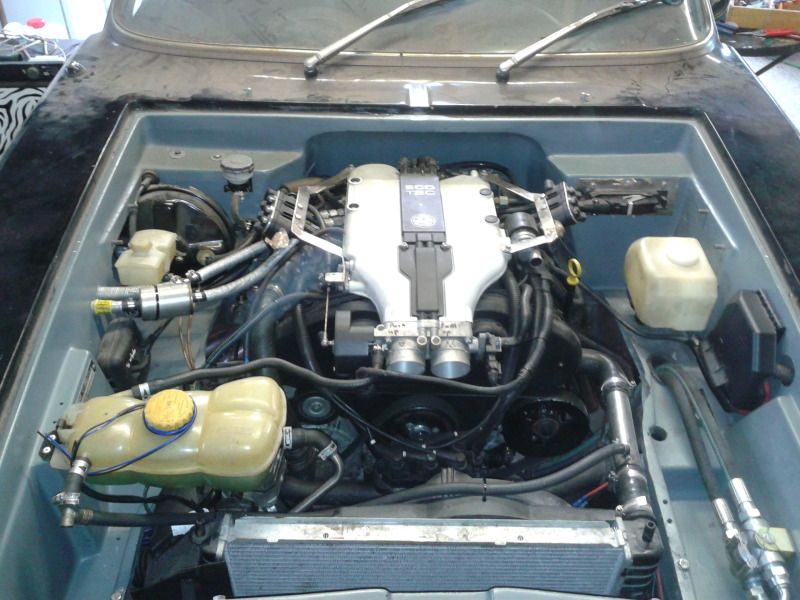
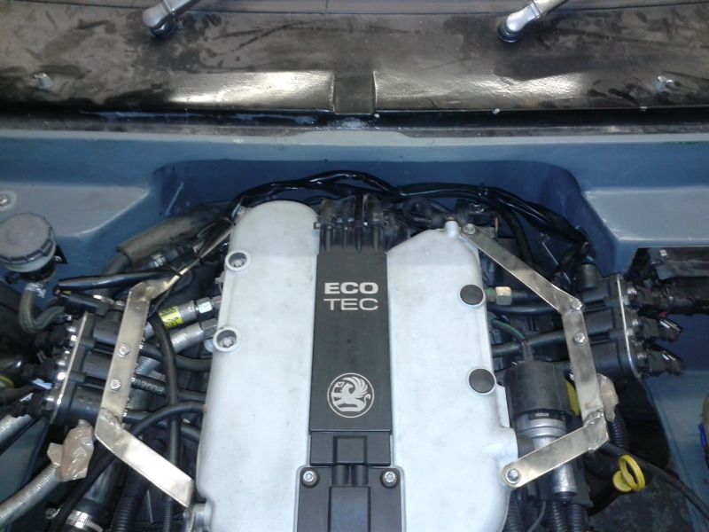
Hello again!! I've found a little time to mess about in the garage. I've mostly been cleaning up everyone elses s***, but its all sparkly now:
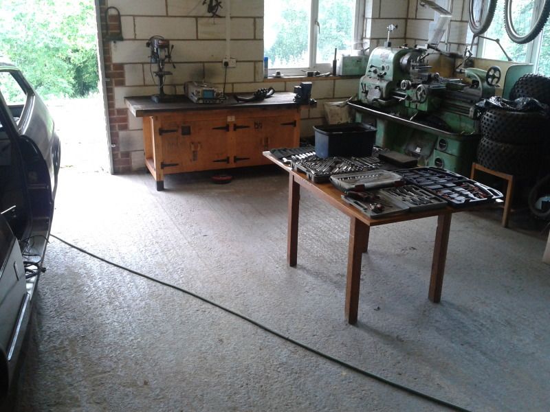
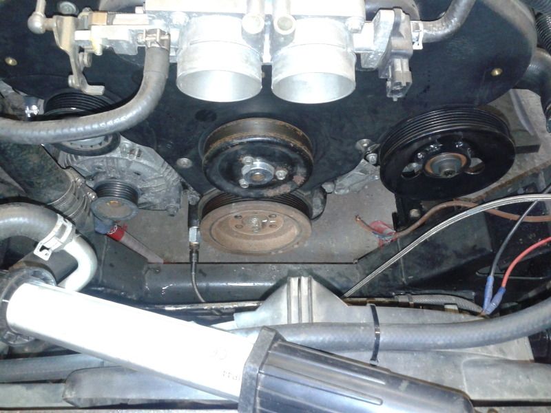
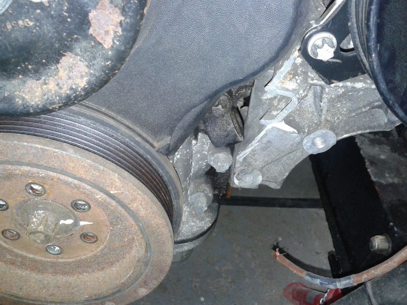
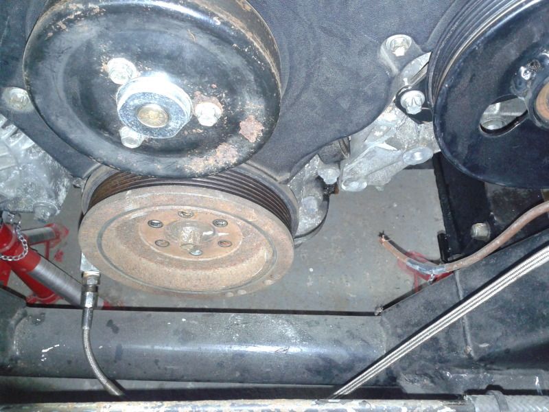
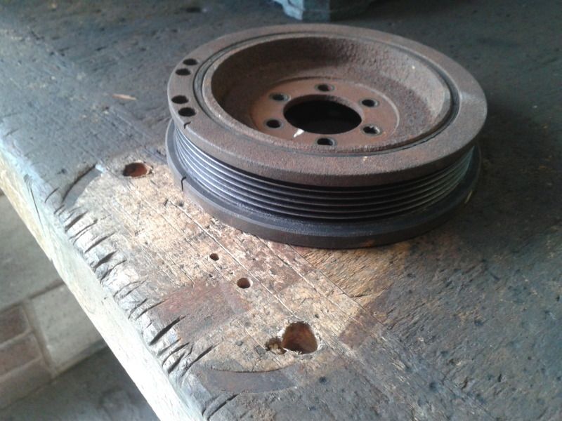
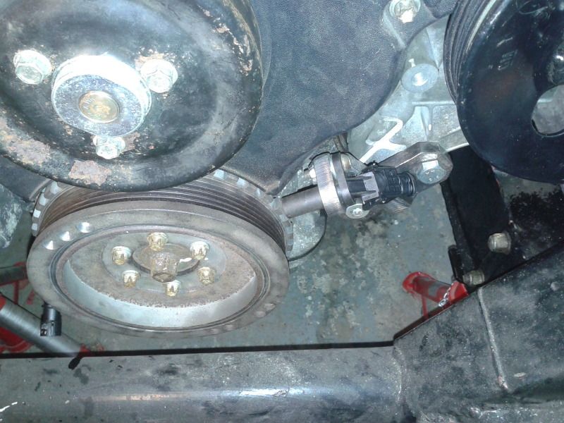
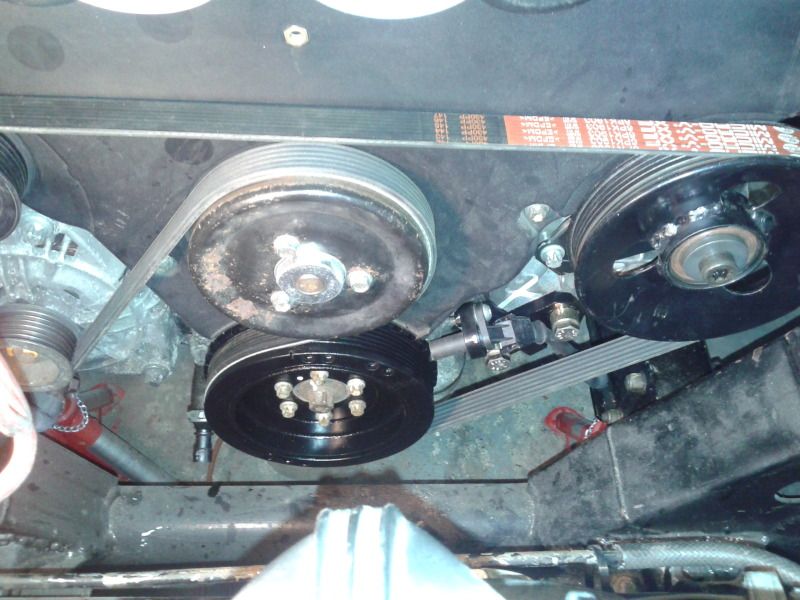
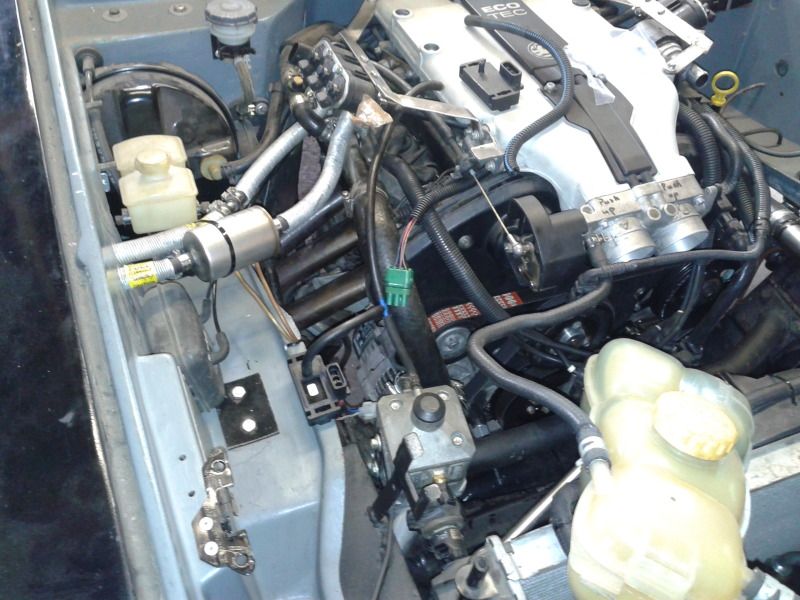
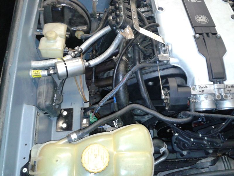
So I've started looking into the next idea to fix the engine running problem. I'm going to machine up the engine pulley to become the new trigger wheel and mount the sensor up front. Here are a few photos of the front end and pulley.
I really really really really can't wait to have this part of the project behind me, and get back on with finishing the car.
Next port of call for today is to find a new inverted to get the lathe running again.
More to come.
I've ordered the recommended crank sensor for a machined front pulley , the 3rd one now!
Anyway when I had dropped the CRO off with my friend, we had time for this fun beforeI returned.......
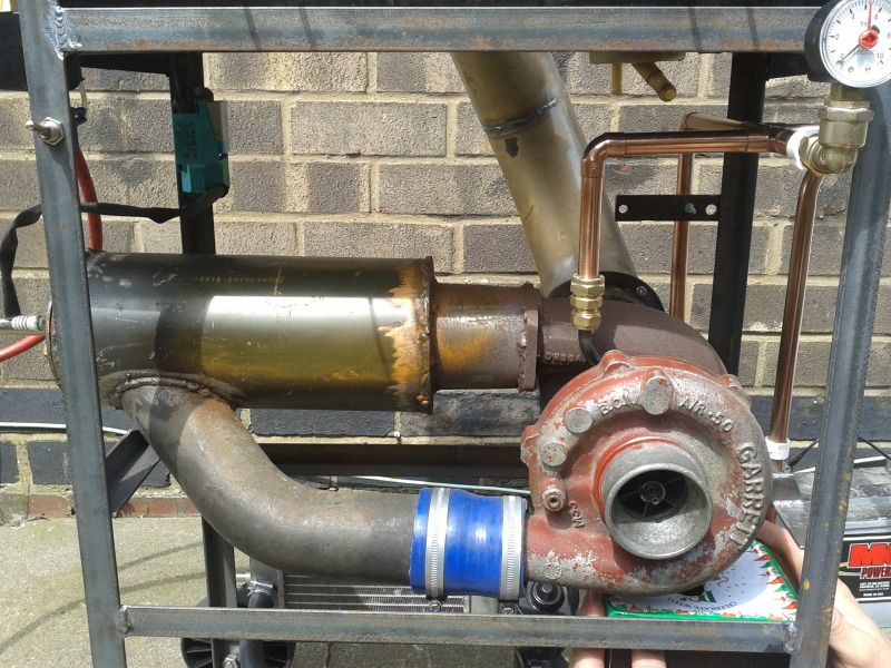
So a few months back I went to see my good buddy pete, (we were at uni together) now most people would be happy to laze about and catch up but not pete, first thing saturday morning we were off to the scrappy to get the bits to make a jet engine.
We got did it, we made a jet engine in well under 48 hours and fired it up that weekend, its was a lot of fun. Pete did the research before I got there, he did lots of cutting and lateral thinking around problems, and sourcing the parts, I did the calculations for the flame tube and the welding.
When I turned up this time, he and another friend have mounted the jet in a BBQ!!!!
What an Amxing BBQ, we fired it up for the first time in its new home, and it cooked a sausage in no time!
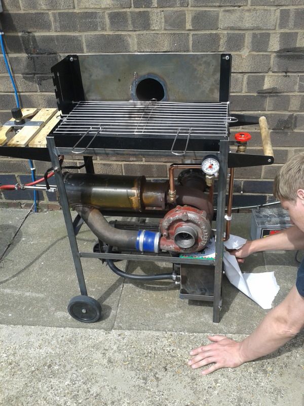
Here's the bit me and pete made:
This is how to start it with the leave blower:

And antoehr vid of it running:

Cool or what (well maybe pointless)
, the 3rd one now!Anyway when I had dropped the CRO off with my friend, we had time for this fun beforeI returned.......
So a few months back I went to see my good buddy pete, (we were at uni together) now most people would be happy to laze about and catch up but not pete, first thing saturday morning we were off to the scrappy to get the bits to make a jet engine.
We got did it, we made a jet engine in well under 48 hours and fired it up that weekend, its was a lot of fun. Pete did the research before I got there, he did lots of cutting and lateral thinking around problems, and sourcing the parts, I did the calculations for the flame tube and the welding.
When I turned up this time, he and another friend have mounted the jet in a BBQ!!!!
What an Amxing BBQ, we fired it up for the first time in its new home, and it cooked a sausage in no time!
Here's the bit me and pete made:
This is how to start it with the leave blower:
And antoehr vid of it running:
Cool or what (well maybe pointless)
Thanks guys
A little update on the scimitar......
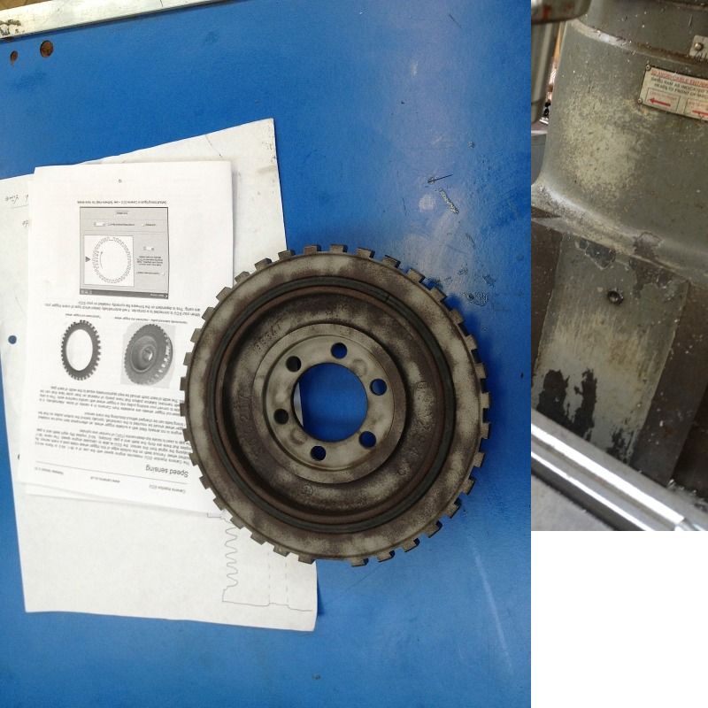
So I finally gave in and ordered another CPS, and a great opportunity presented itself. I needed the pulley machining to make a 36-1 trigger wheel to give this ECU its best chance of working.
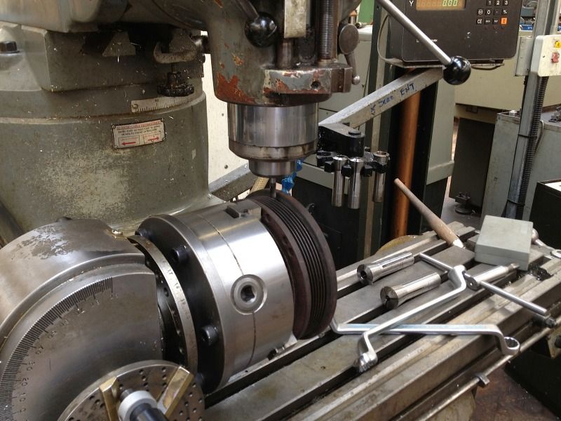
A student at college, on a higher level course was looking to gain some experience in the workshop, so I asked him if he would like to machine the pulley for me....... The following photos are the amazing results that were achieved.
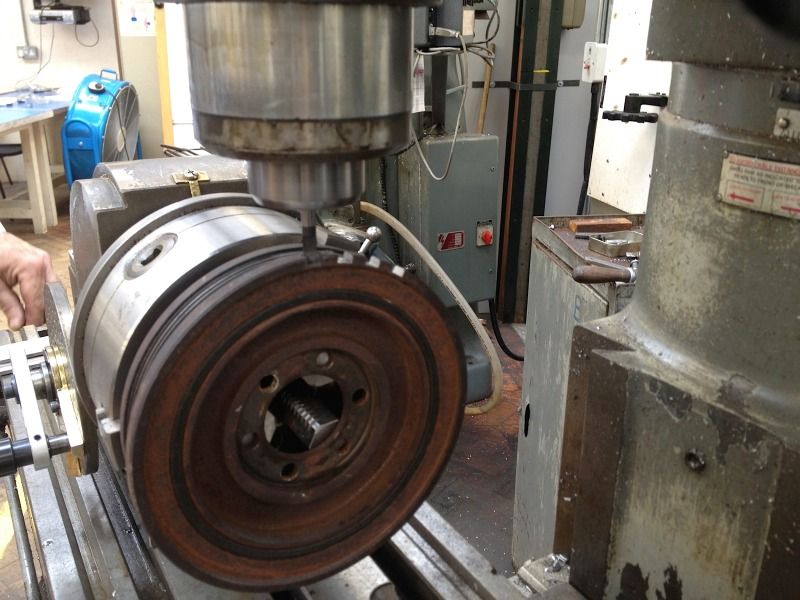
Initially the inner surface was cleaned up a bit to register correctly on the indexing head on the bed of the milling machine.
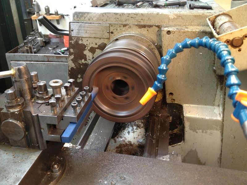
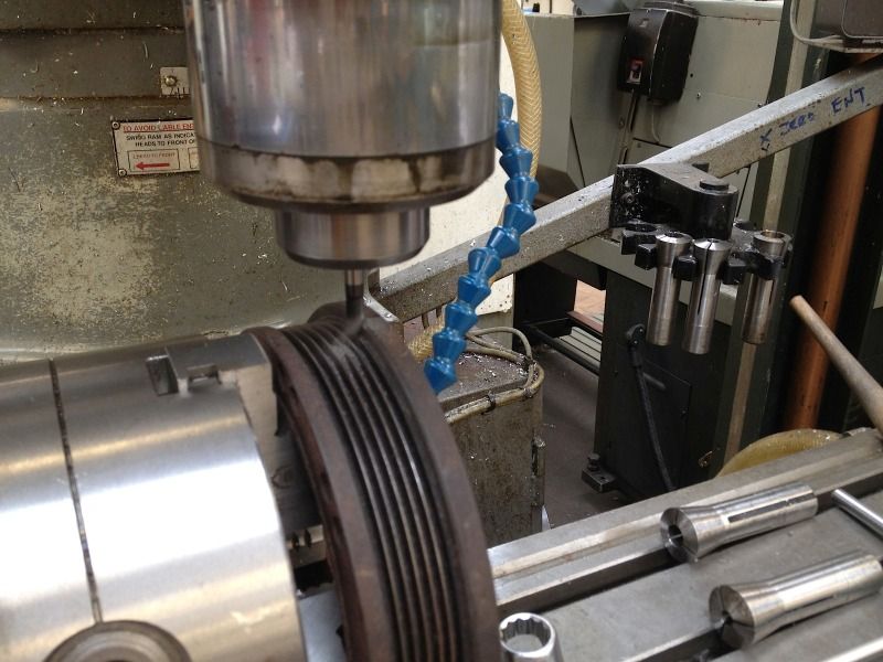
Then the pulley was mounted in the milling machine then Ben used a 7mm cutter to mill out the teeth before turning the pulley 10 degrees to cut the next.
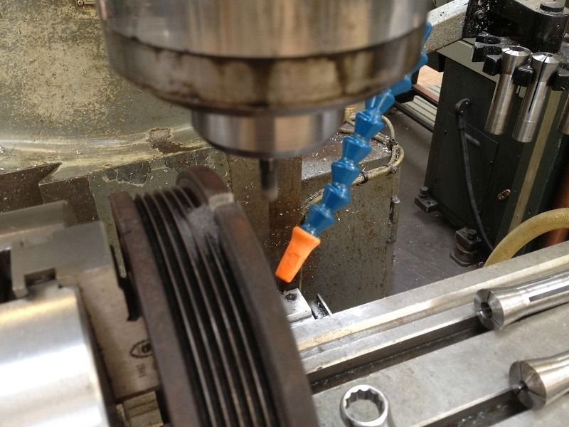
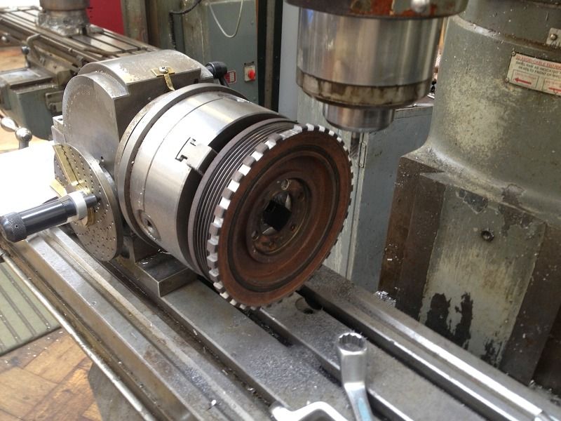
He was even kind enough to clean up the part afterwards.
I owe Ben big time for his excellent work, and can’t wait to get the sensor through in the post and make the mount up.
More to come
A little update on the scimitar......
So I finally gave in and ordered another CPS, and a great opportunity presented itself. I needed the pulley machining to make a 36-1 trigger wheel to give this ECU its best chance of working.
A student at college, on a higher level course was looking to gain some experience in the workshop, so I asked him if he would like to machine the pulley for me....... The following photos are the amazing results that were achieved.
Initially the inner surface was cleaned up a bit to register correctly on the indexing head on the bed of the milling machine.
Then the pulley was mounted in the milling machine then Ben used a 7mm cutter to mill out the teeth before turning the pulley 10 degrees to cut the next.
He was even kind enough to clean up the part afterwards.
I owe Ben big time for his excellent work, and can’t wait to get the sensor through in the post and make the mount up.
More to come
Thanks BigTom
A little update then,
Nothing too exciting but its moving in the right direction.
Got hte oilstat through in the post and started to measure the hoses up. The pulley is being balances this week I can't really make a bracket until thats back on the engine.
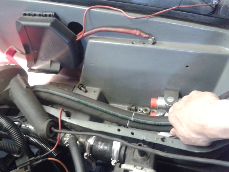
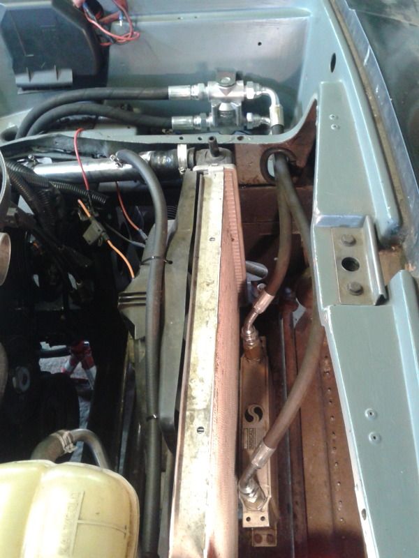
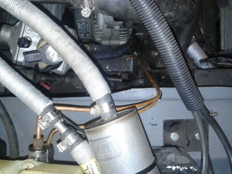
The oil pipes have to go down to the chassis then up the suspension pillar to the oil stat which will be where the battery used to be. The exhaust is quite close to where the hoses come out of the block so some kind of heat shield will need making to protect them. The from the stat to the cooler through the now hole where the battery used to be. I cut up an old fuel hose to neaten up the hole, I'm quite pleased with how it looks.
Also put threadr locked the other side SS exhaust studs.
On another note, I made a little bracket thingy to mount the phone/mp3 player to a false tape, so the phone is there infront of you displaying the song/satnav right infront of the stereo. Photos of this to follow (can't photo it cos was using the phone).
More to come
A little update then,
Nothing too exciting but its moving in the right direction.
Got hte oilstat through in the post and started to measure the hoses up. The pulley is being balances this week I can't really make a bracket until thats back on the engine.
The oil pipes have to go down to the chassis then up the suspension pillar to the oil stat which will be where the battery used to be. The exhaust is quite close to where the hoses come out of the block so some kind of heat shield will need making to protect them. The from the stat to the cooler through the now hole where the battery used to be. I cut up an old fuel hose to neaten up the hole, I'm quite pleased with how it looks.
Also put threadr locked the other side SS exhaust studs.
On another note, I made a little bracket thingy to mount the phone/mp3 player to a false tape, so the phone is there infront of you displaying the song/satnav right infront of the stereo. Photos of this to follow (can't photo it cos was using the phone).
More to come
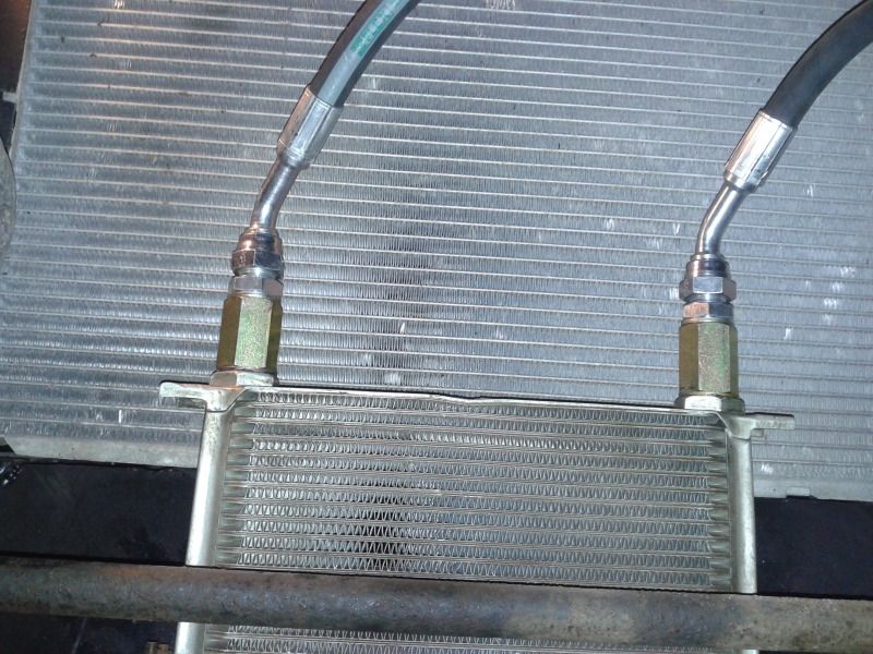
Got the hoses crimped to the right length on wednesday and picked up the newly balanced front pulley.
Trial fitted the hoses yesterday, mounted the cooler and oilstat and tighted up the front two hoses.
I'll leave the engine hoses off for now to give access to the engine while making the new CPS mount (todays task).
More to come
Trial fitted the hoses yesterday, mounted the cooler and oilstat and tighted up the front two hoses.
I'll leave the engine hoses off for now to give access to the engine while making the new CPS mount (todays task).
More to come
Hi lozzzzzz
Nice work it looks like its taking shape now.
Just one concern I have about the trigger wheel, I noticed you have machined it into the torsional part of the crank damper ie the part that flexes, wont this have an effect on your crank signal to the ecu ?.
Have a look through this its an iteresting read.
http://racingarticles.com/files/general-damper-art...
I'll have a read of that at some point, looks interesting.
This has been raised else where, the general opinion is that the movingment is very small indeed, you can feel that it doesn't move, even if you use a lever. It didn't chatter the milling bit when it was being cut, and its been done several times before.
Either way, its my next cheapest option so I'm sort of stuck with it, if it doesn't work then its time to upgrade ECUs and try the OEM sensor and wheel again
Only time will tell
Did a little more this morning, it felt like it always used to, I just got stuck in, realised I was hungry when I was shaking, single track mind, I loved it this morning.
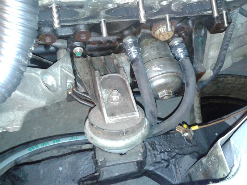
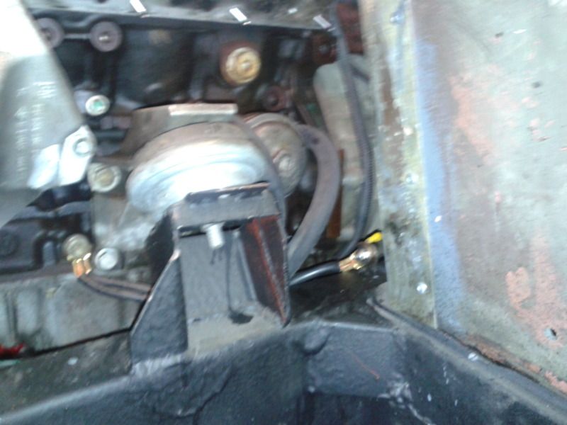
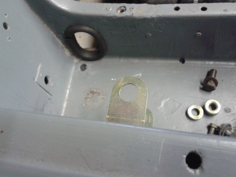
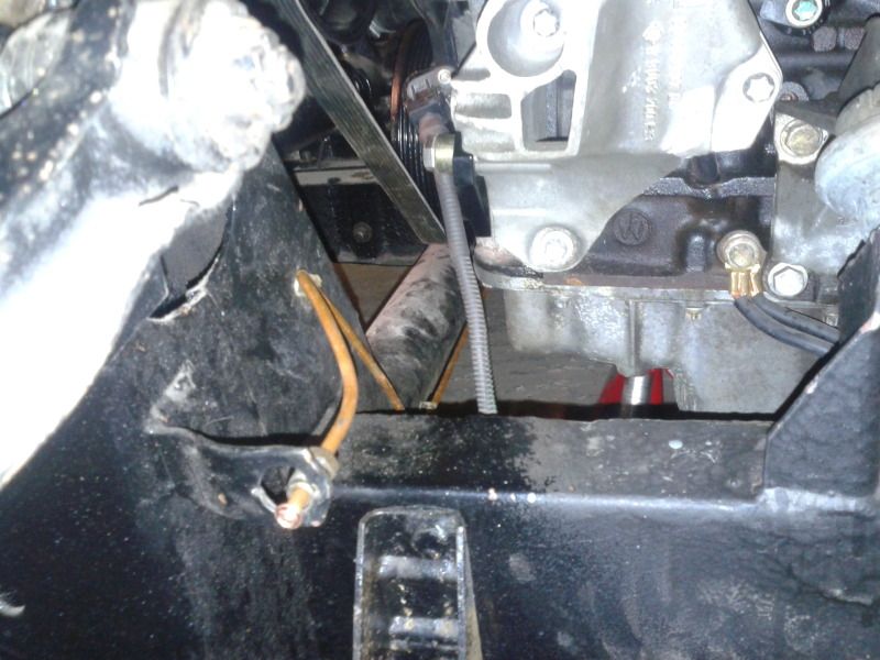
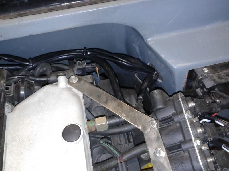
Basically made the sensor mount for trigger wheel pulley.
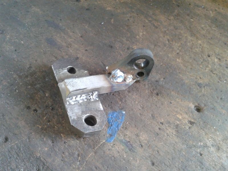
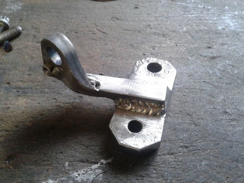
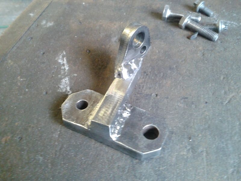
And here's where it goes
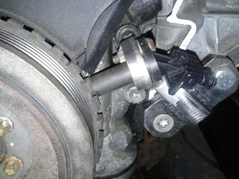
If its assembles, it foals on the trigger wheel (just didn't measure enough times), so I can use washers to get the spacing right, better too close than too far. I'll aim for 0.8mm I think, after the paint dries.
More to come
This has been raised else where, the general opinion is that the movingment is very small indeed, you can feel that it doesn't move, even if you use a lever. It didn't chatter the milling bit when it was being cut, and its been done several times before.
Either way, its my next cheapest option so I'm sort of stuck with it, if it doesn't work then its time to upgrade ECUs and try the OEM sensor and wheel again
Only time will tell
Did a little more this morning, it felt like it always used to, I just got stuck in, realised I was hungry when I was shaking, single track mind, I loved it this morning.
Basically made the sensor mount for trigger wheel pulley.
And here's where it goes
If its assembles, it foals on the trigger wheel (just didn't measure enough times), so I can use washers to get the spacing right, better too close than too far. I'll aim for 0.8mm I think, after the paint dries.
More to come
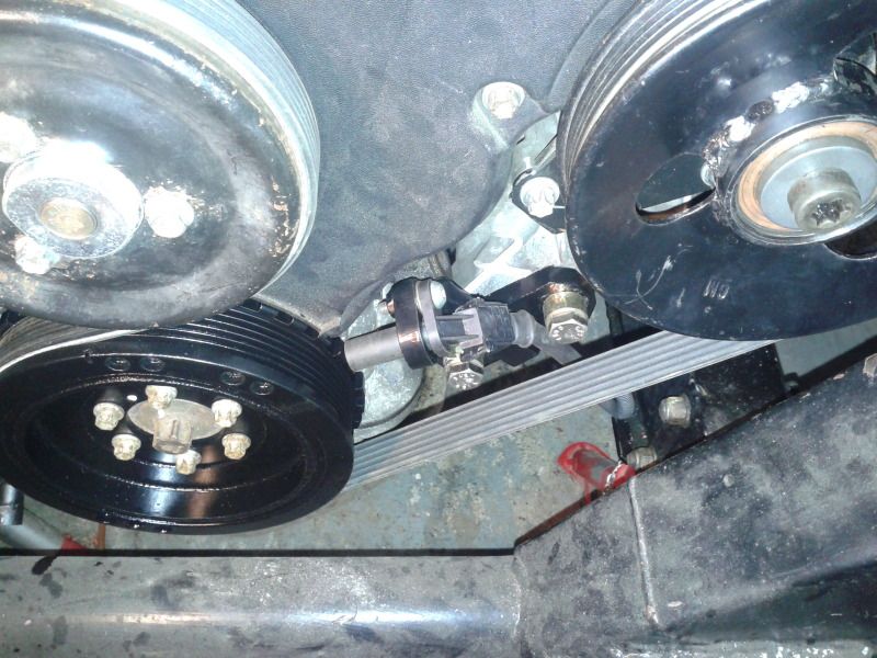
Got the sensor on and wired up yesterday, I'm pleased it looks nice and neat and tucked away.
And tried it...
Now I've spoken too soon in the past, but I think it might just be WORKING I turned the key well over 30 times, and the LED went green every time
I'll tentatively connect other parts and keep trying it with my fingers firmly crossed that thats it. Its looking good at the mo though.
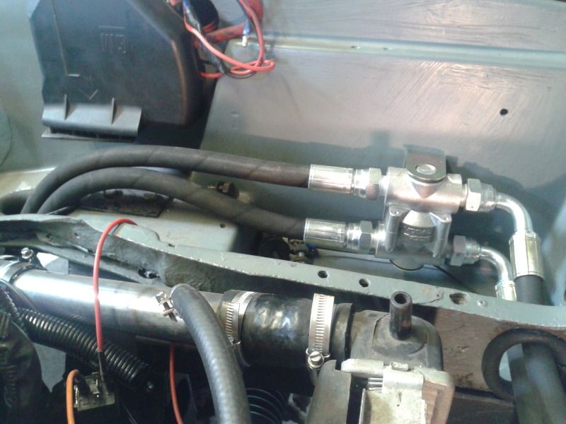
So I'm on the assemble now, first was the coil back on, but there were no front brake lines yet so I made up sone new (ish) ones that go straight from the master to each side, the bias valve thingy is no longer needed see (there is an adjustable one in the car now).
And they look like this
Not masses of progress toningt, but, all being well, a majorstep forward in overcoming a 9 month "glitch"
More to come
And tried it...
Now I've spoken too soon in the past, but I think it might just be WORKING
I turned the key well over 30 times, and the LED went green every time I'll tentatively connect other parts and keep trying it with my fingers firmly crossed that thats it. Its looking good at the mo though.
So I'm on the assemble now, first was the coil back on, but there were no front brake lines yet so I made up sone new (ish) ones that go straight from the master to each side, the bias valve thingy is no longer needed see (there is an adjustable one in the car now).
And they look like this
Not masses of progress toningt, but, all being well, a majorstep forward in overcoming a 9 month "glitch"
More to come
A well overdue update with the project now that the photobucket account is unlocked.
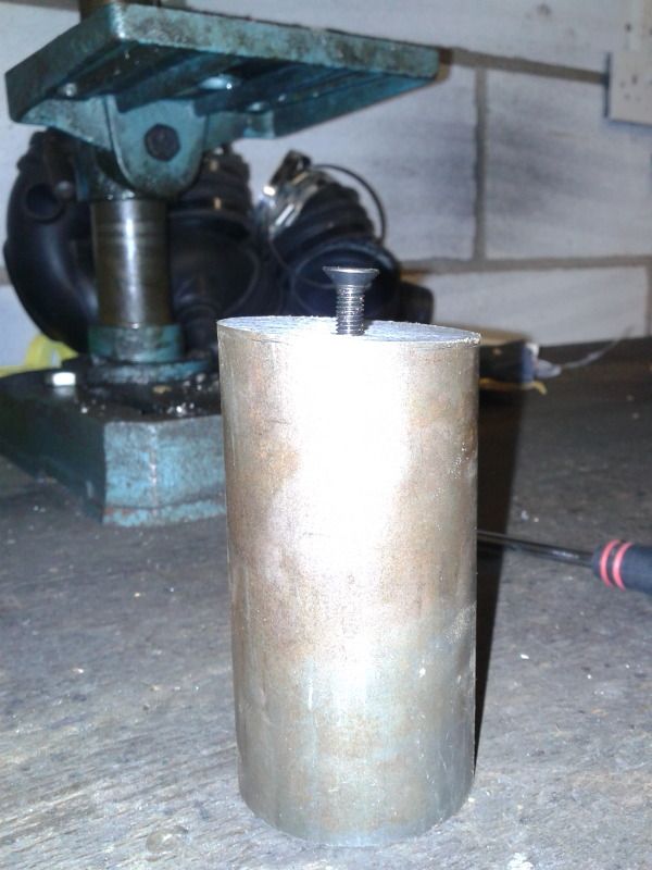
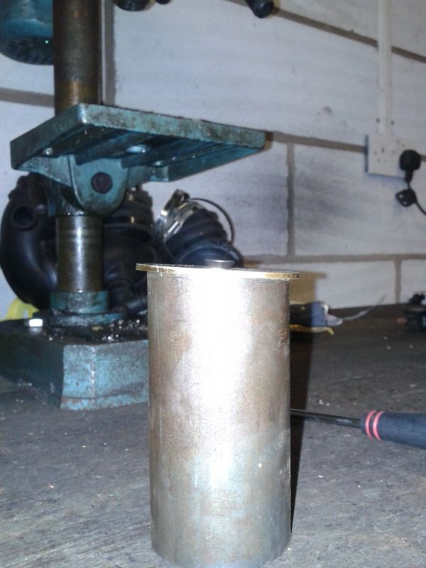
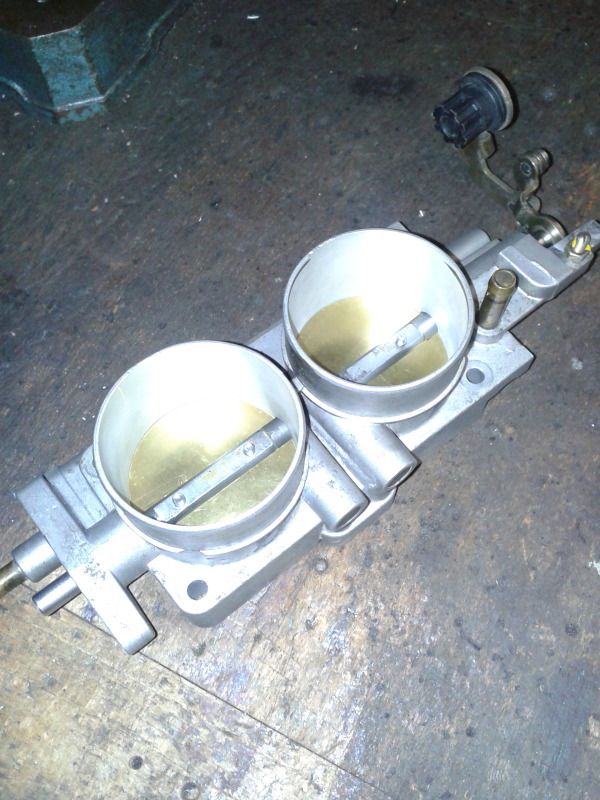
To start with I thought I'd try my hand at boring the throttle body out, I thought I'd put it on the lathe to increase the bore then use a bit of bar with an angled top mounted in the lathe, with a sheet of brass screwed to it to make the new butterfly (see the pics).
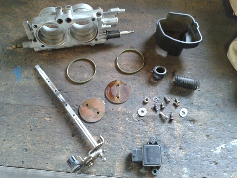
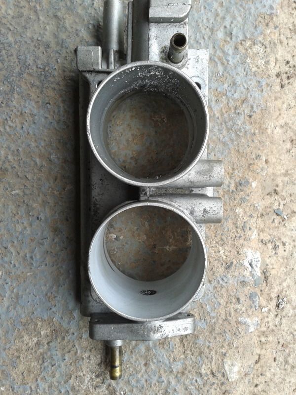
Stripped the throttle body down first (a spare one I bought incase it went wrong )
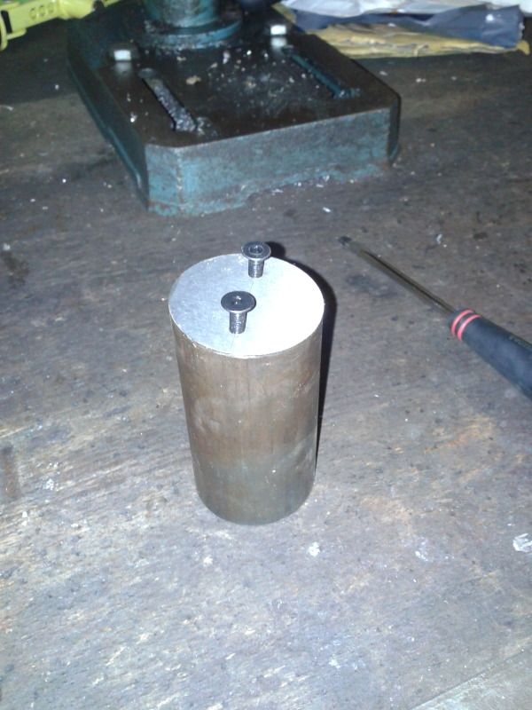
Then had a think about how best to mount it (turns out the best way would be on a milling machine but meh), I glued a couple of small strips of sheet steel to the bottom as the flat bas of the throttle body has one raised section. This way the flat bottom will be parallel to the face of the four jaw chuck.
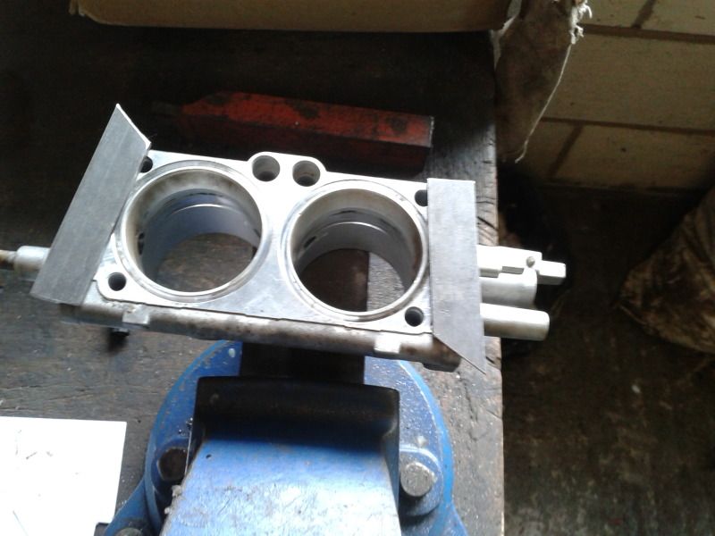
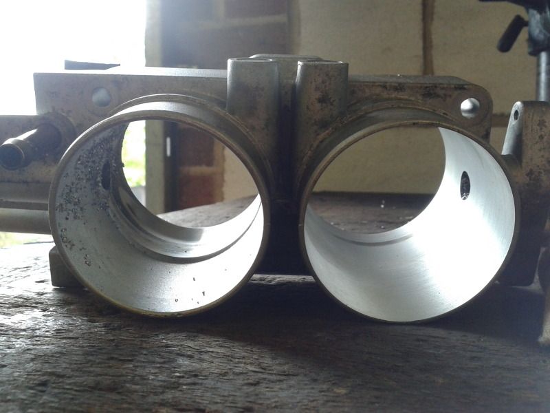
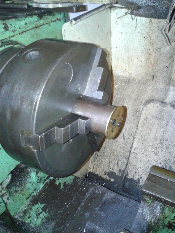
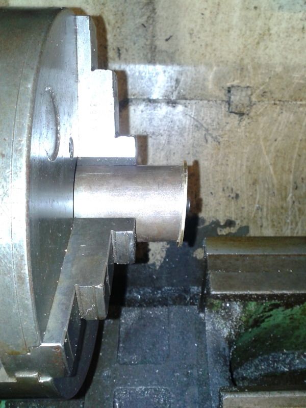
I really should have had a photo of it in the lathe, it took a while to get it central with the dial gauge and make more difficult with all the machined surfaces being against the face of the chuck, so I had to kind of guess and centralise it off the cast inner surface of the upstream side. It came out well though, here you can see the right bore done and the left still to do
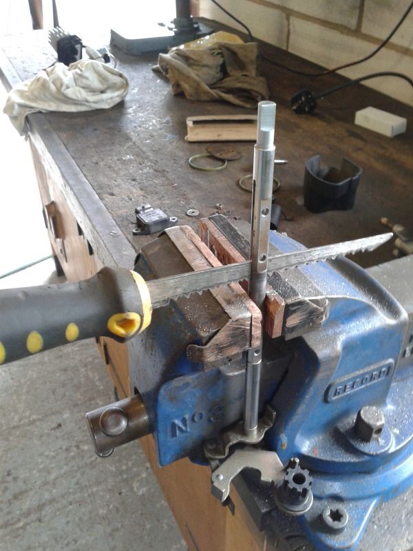
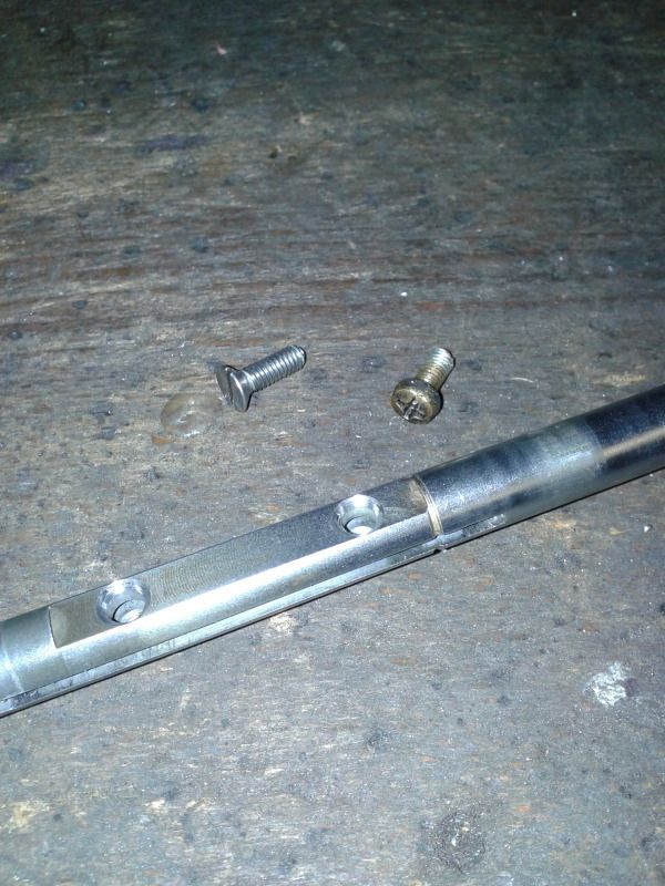
The slits in the spindle needed widening a little, this was a proper "farm engineering" job, I used a wood saw and it worked.
This was the relatively easy bit done, the butterflies were the tricky bit really. With an increase from 54mm dia to 57mm the increase in CSA is 11% which should hopefully equate to an increase in power at the very top end of the revs.
I "umm'd and ahh'd" for a while about how best to make the slanted top bar for making the butterflies. Then gave in and used the workshop at work. Unfortunately I can't say I made the parts in the next couple of photo's but Dave in the workshop took the helm and did a fantastic job. First of all making surface grinding the bar to correct angle.
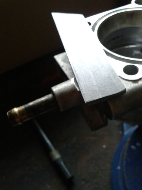
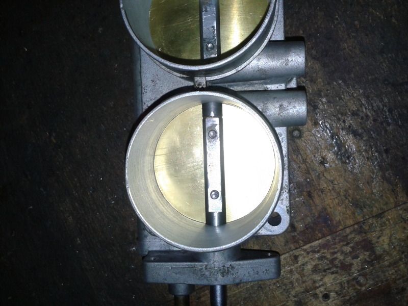
This was mounted in the lathe and the butterfly turned so that it would come out with slightly slanted side to seal in the body at 4 degrees.
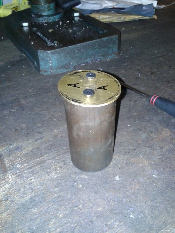
The Spindle has also been countersunk and smaller machine screws bought
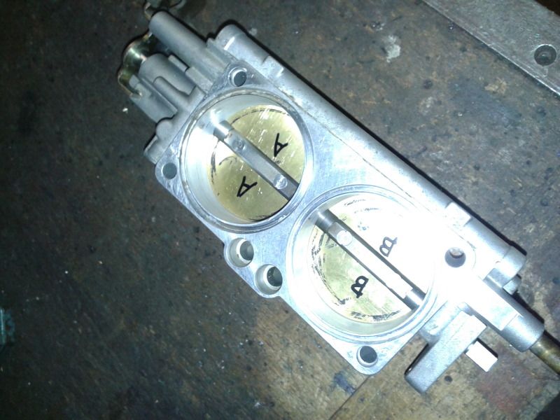
This is when I found that the way the body was clamped in the four jaw chuck (using only two jaws) had meant that the bore were 0.02mm oval but this was easy enough to fix by gently sanding the edges of the butterflies until the profile matched the bore. And here's the finished item, its been tried and seals sufficiently well that the idle valve settings didn't need changing The rolling road tuning session will give the answer as to whether all this has been worth the effort.
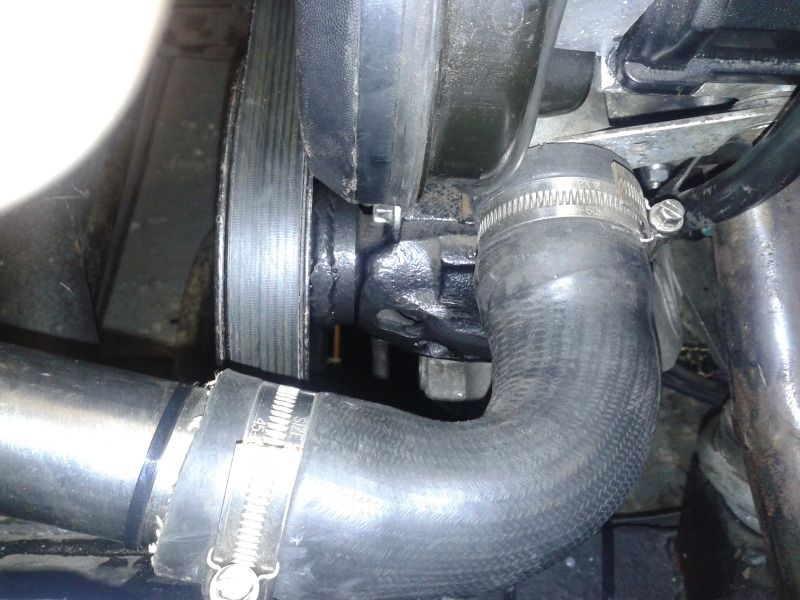
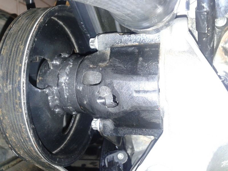
Next I had a go at the idler puller (was the PAS) I wasn’t too happy with the wobble it had, so I got a new bearing for it (was the timing belt idler bearing), but this didn’t cure it, the problem being that the PAS pulley is much bigger diameter than the timing belt idler would have been so any movement in the bearing is very amplified by the size of the pulley. Long story short… I put a second bearing in with the first, right next to it, so now there is no movement sideways at all, you can just about make out the extended hub of the pulley in these photos.
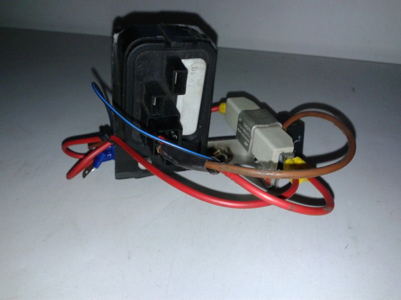
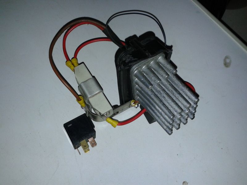
Another little project was to make a little section of electricery for the front of the car with some relays, a resistor and the slow start jobby for the interior blower.
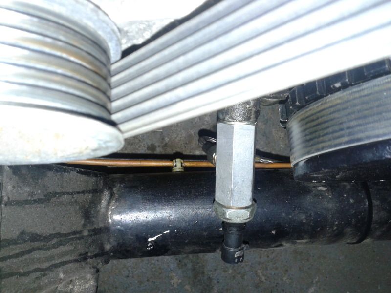
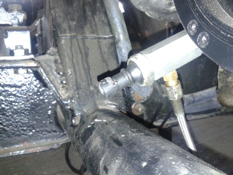
Another little job was to fit an adapter thingy that means I can have the oil pressure gauge and the low oil pressure warning sender both attached to the oil system. I’ve wired this up with the oil level warning sender and the coolant level warning sender into a circuit with a little relay so that if anything out of order a buzzer sounds (which can be silenced when starting the car with a push button)
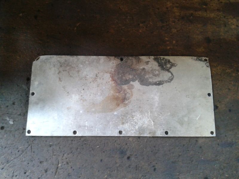
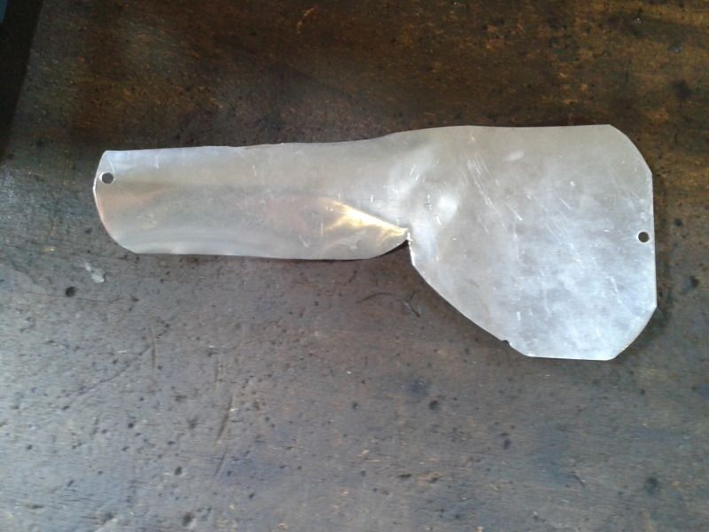
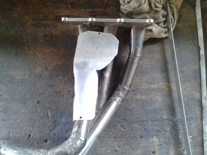
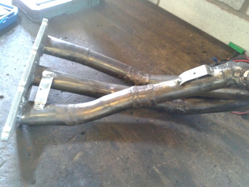
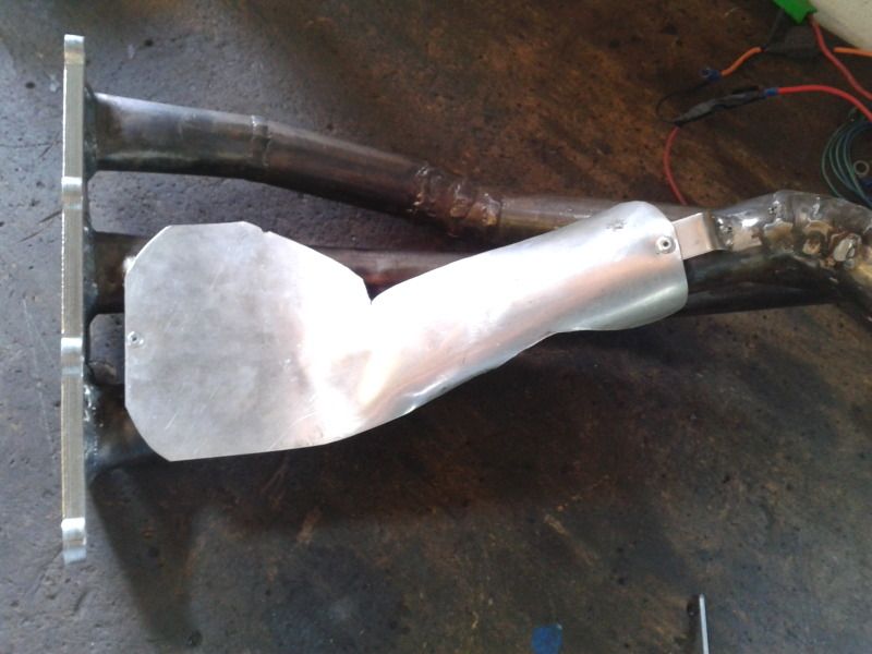
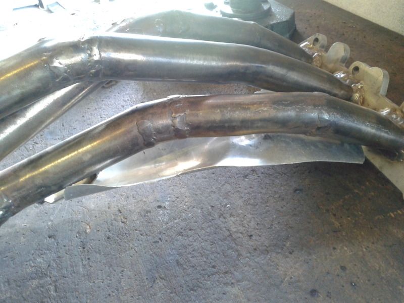
The new oil lines go pretty close to the exhaust manifold, so I think I’m going to get them ceramic coated (as this will help with corrosion too), but in addition I’ve made a little heat shield mounted on the exhaust manifold that goes between the pipes and the… pipes
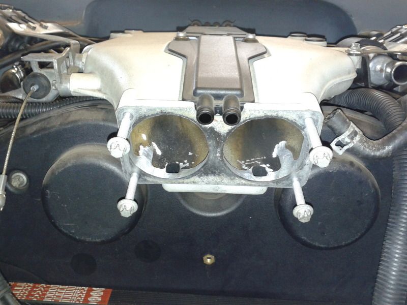
I had to have the manifold off again to further grind out the throttle body mounting point so there is no lip between the throttle body and the manifold.
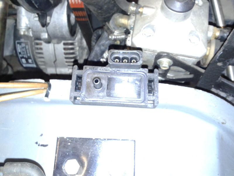
The MAP sensor was neatly mounted on the engine, tucked away, turns out they don’t like heat or vibration so that’s packed up already and I had to fit a new one on the side of the engine bay.
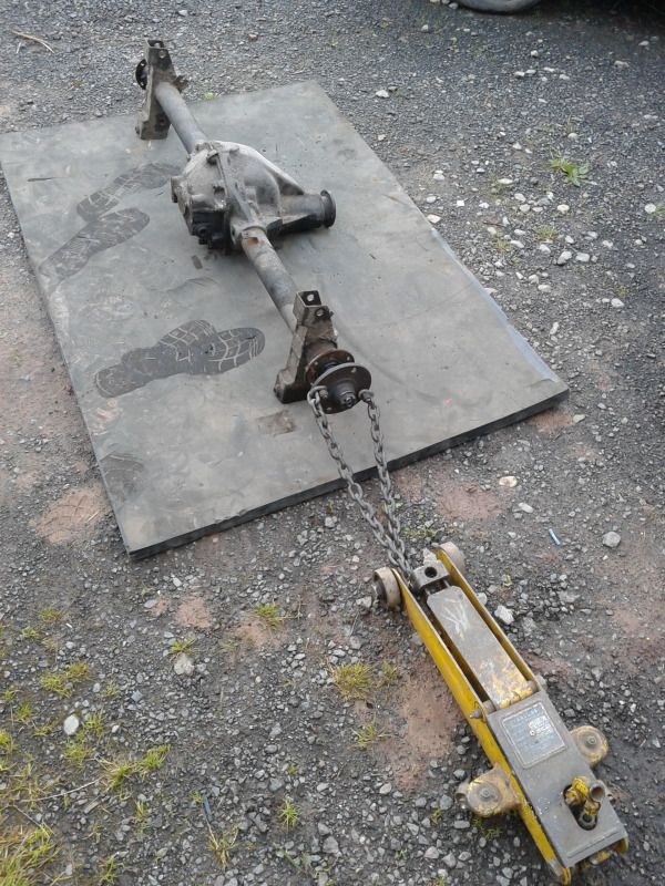
Got the axle off (again) and started to strip it in an attempt to change the diff to the quaiffe item.
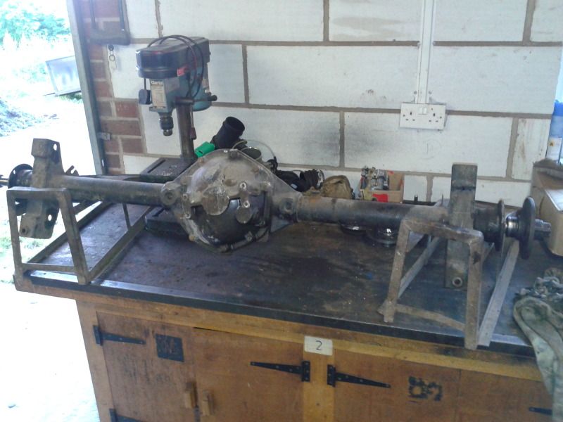
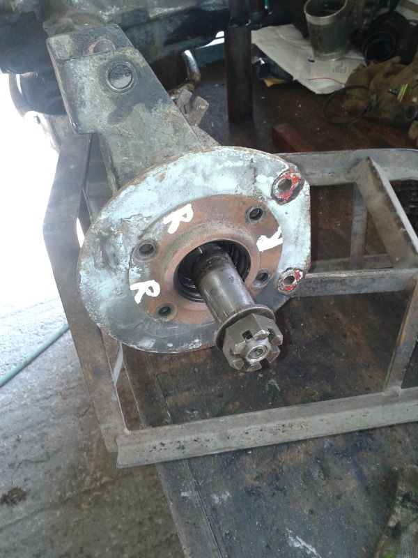
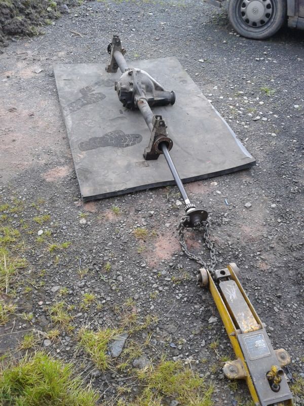
Got the drive flanges off and put the sacrificial one on (the bent one) complete with half shaft puller (chain and jack)
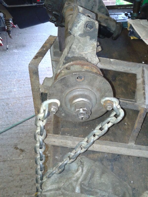
And just three snags of the chain later…..
Took the diff out and took it to work and took the accurate measurements, only to figure out that its really b***dy difficult to get the bearings off, and I’m still at it.
In the mean time This rear disc conversion is available if anyone fancies it. It includes the caliper mounts made by Sam Laurenzelly (I think that’s his surname) who was a scimitar man not so long ago and started the V8 Church website, the audi calipers will come with it and the spacers of different thicknesses to get the disc in the right place, the calipers have been modified to accept the scimitar hand brake cable. So all that would need finding is new discs and flexi hoses (they’re not included).
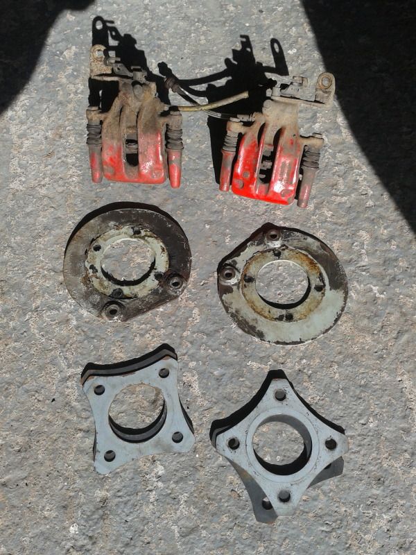
Bear in mind that these weren’t quite strong enough and put a little too much bias on the front brakes, so something would need doing about that. This conversion would work really well with a front brake conversion (if smaller piston calipers were used up front).
Over the last couple of days I’ve been busy getting all the wiring squared away, the LC-1 is is connected and giving a proper lambda ratio reading through the Canems ECU, the LPG ECU is fully connected to the Canems ECU and tank, but not yet the other LPG components, and the front end loom is back in the left wing. The engine is running perfectly with the fault not having shown is face again, and the idle is much sweeter now its not 18 AFR.
More to come
To start with I thought I'd try my hand at boring the throttle body out, I thought I'd put it on the lathe to increase the bore then use a bit of bar with an angled top mounted in the lathe, with a sheet of brass screwed to it to make the new butterfly (see the pics).
Stripped the throttle body down first (a spare one I bought incase it went wrong
)Then had a think about how best to mount it (turns out the best way would be on a milling machine but meh), I glued a couple of small strips of sheet steel to the bottom as the flat bas of the throttle body has one raised section. This way the flat bottom will be parallel to the face of the four jaw chuck.
I really should have had a photo of it in the lathe, it took a while to get it central with the dial gauge and make more difficult with all the machined surfaces being against the face of the chuck, so I had to kind of guess and centralise it off the cast inner surface of the upstream side. It came out well though, here you can see the right bore done and the left still to do
The slits in the spindle needed widening a little, this was a proper "farm engineering" job, I used a wood saw
and it worked.This was the relatively easy bit done, the butterflies were the tricky bit really. With an increase from 54mm dia to 57mm the increase in CSA is 11% which should hopefully equate to an increase in power at the very top end of the revs.
I "umm'd and ahh'd" for a while about how best to make the slanted top bar for making the butterflies. Then gave in and used the workshop at work. Unfortunately I can't say I made the parts in the next couple of photo's but Dave in the workshop took the helm and did a fantastic job. First of all making surface grinding the bar to correct angle.
This was mounted in the lathe and the butterfly turned so that it would come out with slightly slanted side to seal in the body at 4 degrees.
The Spindle has also been countersunk and smaller machine screws bought
This is when I found that the way the body was clamped in the four jaw chuck (using only two jaws) had meant that the bore were 0.02mm oval
but this was easy enough to fix by gently sanding the edges of the butterflies until the profile matched the bore. And here's the finished item, its been tried and seals sufficiently well that the idle valve settings didn't need changing The rolling road tuning session will give the answer as to whether all this has been worth the effort. Next I had a go at the idler puller (was the PAS) I wasn’t too happy with the wobble it had, so I got a new bearing for it (was the timing belt idler bearing), but this didn’t cure it, the problem being that the PAS pulley is much bigger diameter than the timing belt idler would have been so any movement in the bearing is very amplified by the size of the pulley. Long story short… I put a second bearing in with the first, right next to it, so now there is no movement sideways at all, you can just about make out the extended hub of the pulley in these photos.
Another little project was to make a little section of electricery for the front of the car with some relays, a resistor and the slow start jobby for the interior blower.
Another little job was to fit an adapter thingy that means I can have the oil pressure gauge and the low oil pressure warning sender both attached to the oil system. I’ve wired this up with the oil level warning sender and the coolant level warning sender into a circuit with a little relay so that if anything out of order a buzzer sounds (which can be silenced when starting the car with a push button)
The new oil lines go pretty close to the exhaust manifold, so I think I’m going to get them ceramic coated (as this will help with corrosion too), but in addition I’ve made a little heat shield mounted on the exhaust manifold that goes between the pipes and the… pipes
I had to have the manifold off again to further grind out the throttle body mounting point so there is no lip between the throttle body and the manifold.
The MAP sensor was neatly mounted on the engine, tucked away, turns out they don’t like heat or vibration so that’s packed up already and I had to fit a new one on the side of the engine bay.
Got the axle off (again) and started to strip it in an attempt to change the diff to the quaiffe item.
Got the drive flanges off and put the sacrificial one on (the bent one) complete with half shaft puller (chain and jack)
And just three snags of the chain later…..
Took the diff out and took it to work and took the accurate measurements, only to figure out that its really b***dy difficult to get the bearings off, and I’m still at it.
In the mean time This rear disc conversion is available if anyone fancies it. It includes the caliper mounts made by Sam Laurenzelly (I think that’s his surname) who was a scimitar man not so long ago and started the V8 Church website, the audi calipers will come with it and the spacers of different thicknesses to get the disc in the right place, the calipers have been modified to accept the scimitar hand brake cable. So all that would need finding is new discs and flexi hoses (they’re not included).
Bear in mind that these weren’t quite strong enough and put a little too much bias on the front brakes, so something would need doing about that. This conversion would work really well with a front brake conversion (if smaller piston calipers were used up front).
Over the last couple of days I’ve been busy getting all the wiring squared away, the LC-1 is is connected and giving a proper lambda ratio reading through the Canems ECU, the LPG ECU is fully connected to the Canems ECU and tank, but not yet the other LPG components, and the front end loom is back in the left wing. The engine is running perfectly with the fault not having shown is face again, and the idle is much sweeter now its not 18 AFR.
More to come
A little update.
I feel like I'm working fretty fast at the mo, but there isn't much to show for it, its the kind where you do loads and get nowhere, then it all comes together and there is lots to show, well I've not quite got there yet.
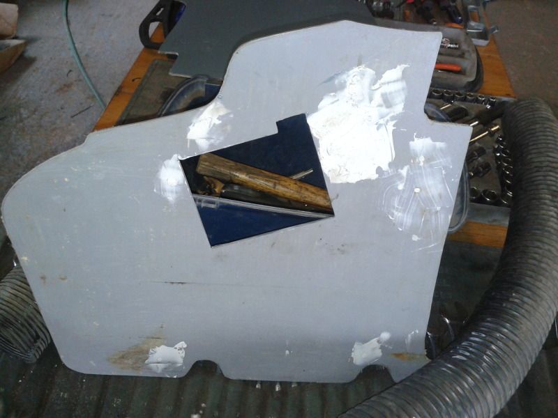
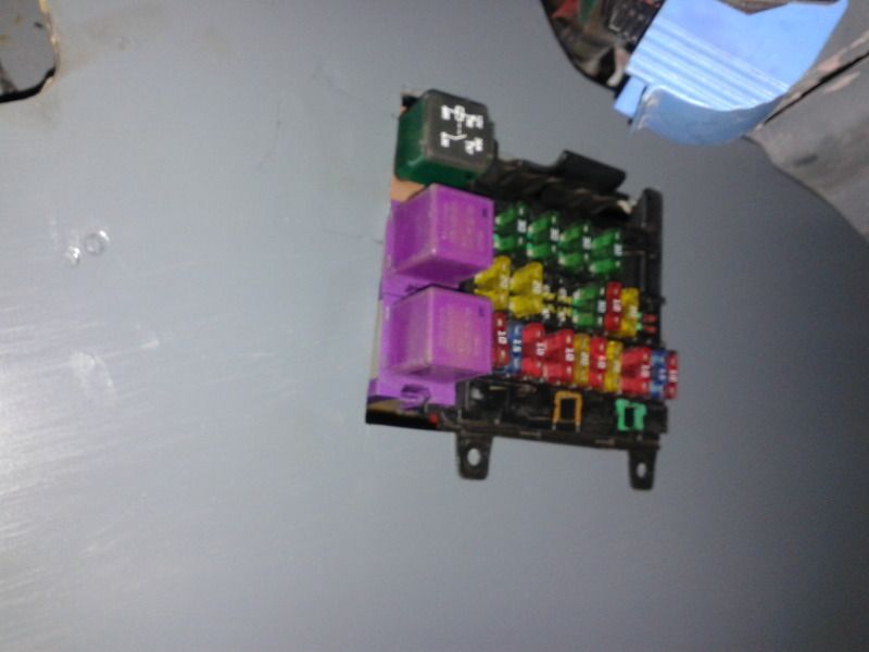
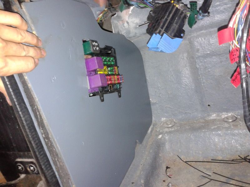
I changed the hole in the passenger kick plate to suit the new fuse box, and it seems to work really well, its a snug fit and clips into the plate with no toehr parts being needed
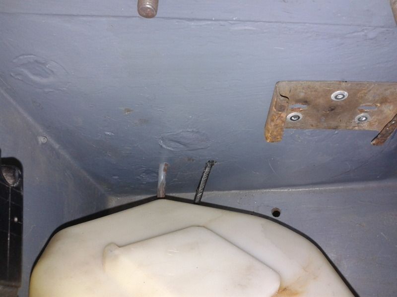
Filled the hole where the loom used to go to the screen wash bottle and used the other small hole that is now available (as I'm not using the rear screen washer any more, then mounted the screen wash in its new slightly different location
But I spent the largest part of today making the housing that will enclose all of the loom I have made above the passengers legs, its nearly there, photo's to follow.
More to come
I feel like I'm working fretty fast at the mo, but there isn't much to show for it, its the kind where you do loads and get nowhere, then it all comes together and there is lots to show, well I've not quite got there yet.
I changed the hole in the passenger kick plate to suit the new fuse box, and it seems to work really well, its a snug fit and clips into the plate with no toehr parts being needed
Filled the hole where the loom used to go to the screen wash bottle and used the other small hole that is now available (as I'm not using the rear screen washer any more, then mounted the screen wash in its new slightly different location
But I spent the largest part of today making the housing that will enclose all of the loom I have made above the passengers legs, its nearly there, photo's to follow.
More to come
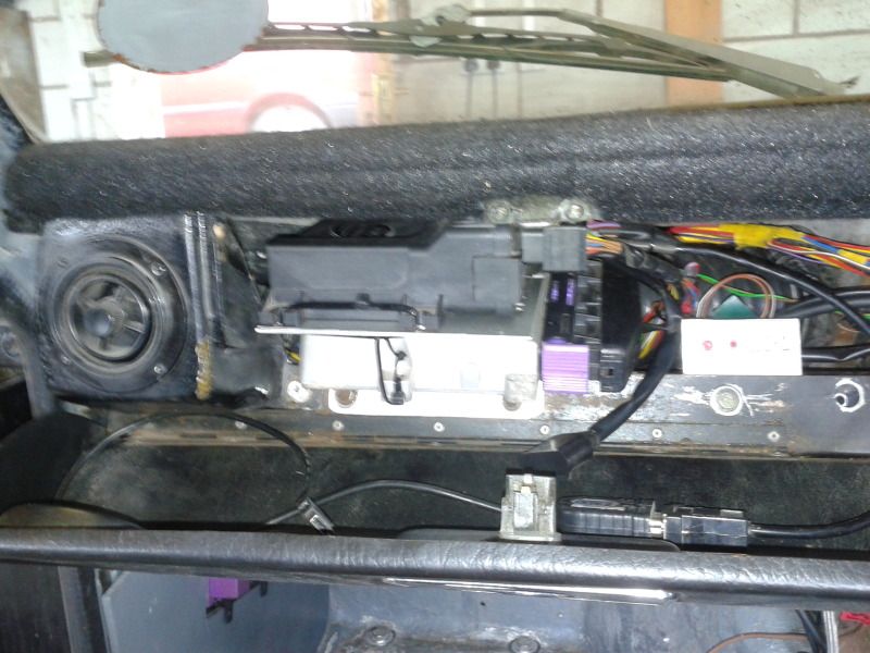
I've finally got all the main section of loom tucket away in the passeneger side, and made this under tray for it.
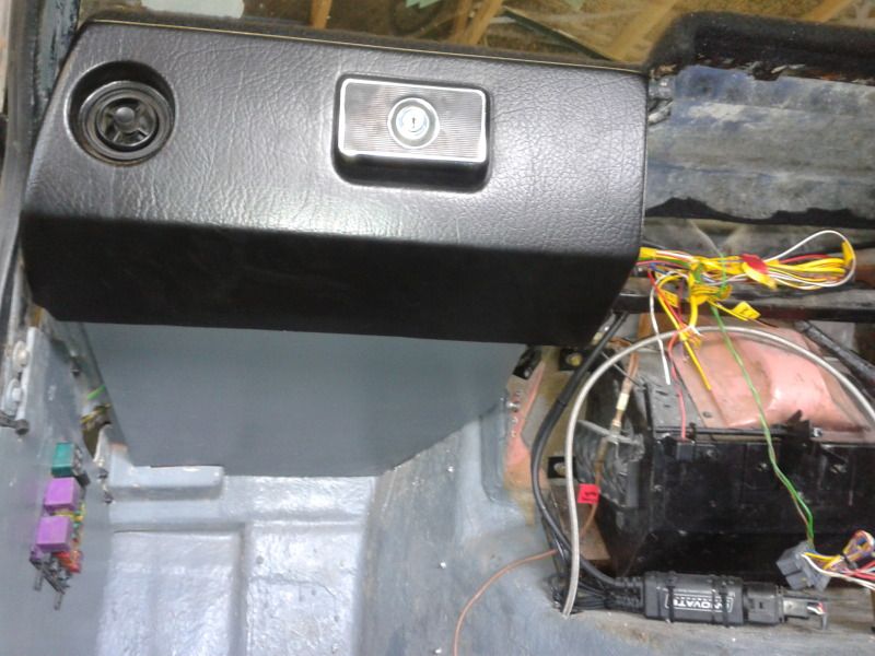
This meant I had to finish all the wiring coming from that section, so the last of the LPG loom now goes through the bulkhead to connect to the rest of the LPG components, you can see the wiring going round the back of the engine.
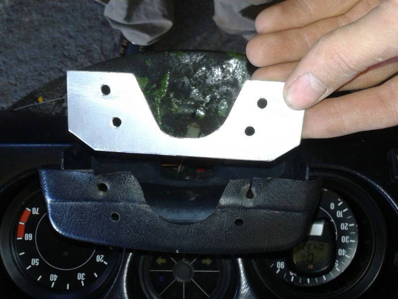
Next I made a bracket to hold both ECUs, there are heat sink connections on the bottom of the Canems ECU, its meant to be connected to something that can disopate heat, so this 2mm ali sheet should do the trick, it certainly conducts heat well (as I found when grinding it).
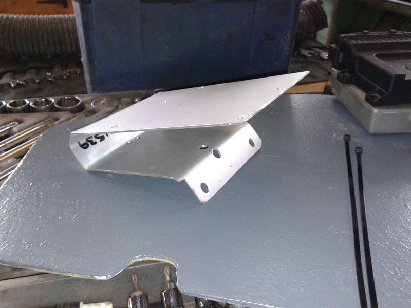
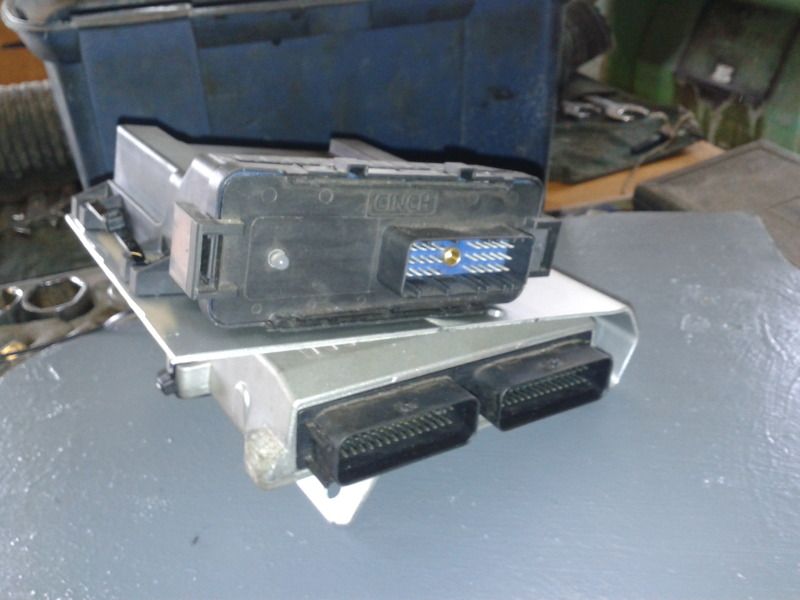
The bracket bolts in with the glove box lid, I've welded some nuts on the loom undertray as it would be a real pain trying to get the nut on past all the electrics in there, its literally full of loom.
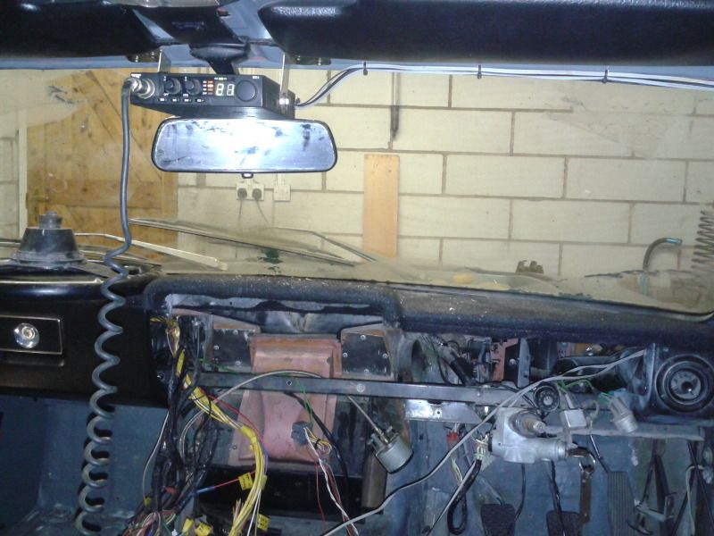
I'm now in the process of making a panel for the lower half of the central dash, this wil have all the fuel pump switches, and the very reduced heat controls.
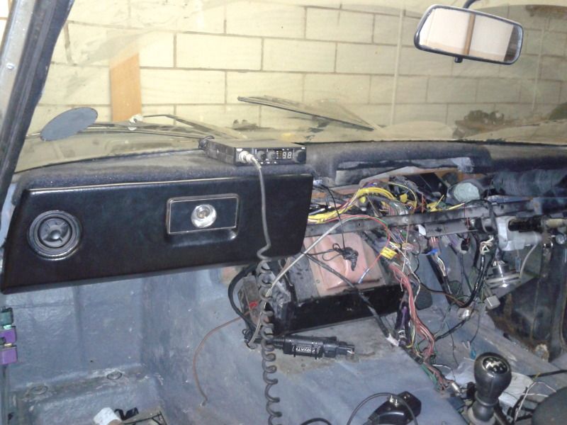
I'm fitting a CB radio, as a few of my mates have them and they're pretty good fun, but can't seem to find a spare place for it, thinging about ontop of th dash, but its really not looking good.
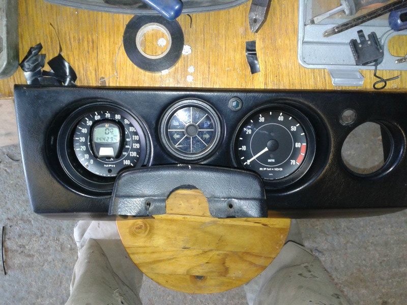
And finally I'm nearly finished fitting the bike speedometer in the originals possition, just got to fix the bulb bracket on the back and check it illuminates the speedo ok.
More to come
This meant I had to finish all the wiring coming from that section, so the last of the LPG loom now goes through the bulkhead to connect to the rest of the LPG components, you can see the wiring going round the back of the engine.
Next I made a bracket to hold both ECUs, there are heat sink connections on the bottom of the Canems ECU, its meant to be connected to something that can disopate heat, so this 2mm ali sheet should do the trick, it certainly conducts heat well (as I found when grinding it).
The bracket bolts in with the glove box lid, I've welded some nuts on the loom undertray as it would be a real pain trying to get the nut on past all the electrics in there, its literally full of loom.
I'm now in the process of making a panel for the lower half of the central dash, this wil have all the fuel pump switches, and the very reduced heat controls.
I'm fitting a CB radio, as a few of my mates have them and they're pretty good fun, but can't seem to find a spare place for it, thinging about ontop of th dash, but its really not looking good.
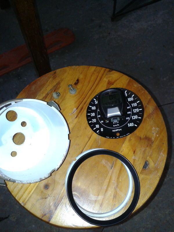
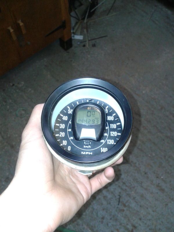
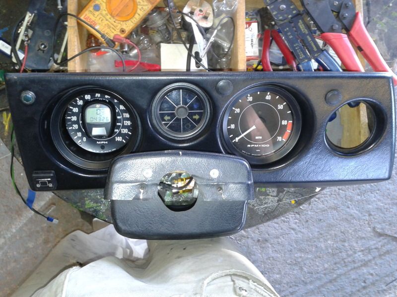
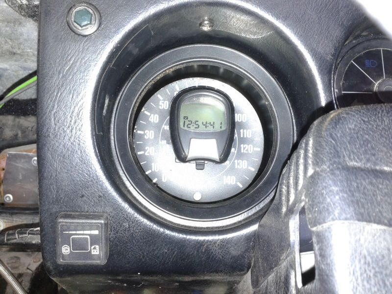
And finally I'm nearly finished fitting the bike speedometer in the originals possition, just got to fix the bulb bracket on the back and check it illuminates the speedo ok.
More to come
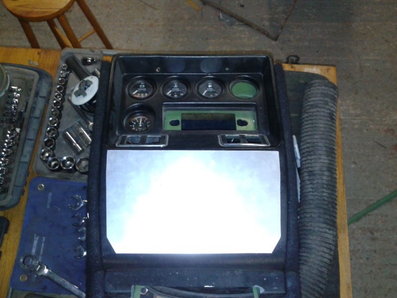
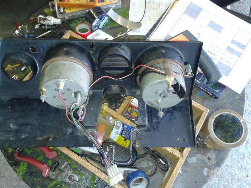
Done a bit more work on it this morning, the reflective white inner surface wasn't taking any light forward to reflect back onto the screen so in the dark, it was beautifully back lit but the screen was completely unreadable.
So, I sprayed the inside of the housing black and set about fitting a light to the dash moulding itself.
This is the old cigarette lighter backlight and housing now mounted in the dial surround. I've decided to bin all the switch illumination and the cig lighter socket illumination as it was all very fiddly and often stopped working, it means I can slightly reduce the loom in that area, I'll keep the switch gear and add new switches rather than replace the lot, and I'll keep the dials all illuminated. Anyway, this means I had a load of bulb holders to play with.
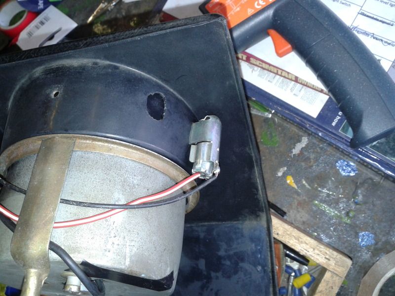
Neatened up the wiring a bit (it was very bodged)
And the finished item. The illumination took a while to get right but it now casts light pretty much only on the screen of the bike speedo.
More to come
So, I sprayed the inside of the housing black and set about fitting a light to the dash moulding itself.
This is the old cigarette lighter backlight and housing now mounted in the dial surround. I've decided to bin all the switch illumination and the cig lighter socket illumination as it was all very fiddly and often stopped working, it means I can slightly reduce the loom in that area, I'll keep the switch gear and add new switches rather than replace the lot, and I'll keep the dials all illuminated. Anyway, this means I had a load of bulb holders to play with.
Neatened up the wiring a bit (it was very bodged)
And the finished item. The illumination took a while to get right but it now casts light pretty much only on the screen of the bike speedo.
More to come
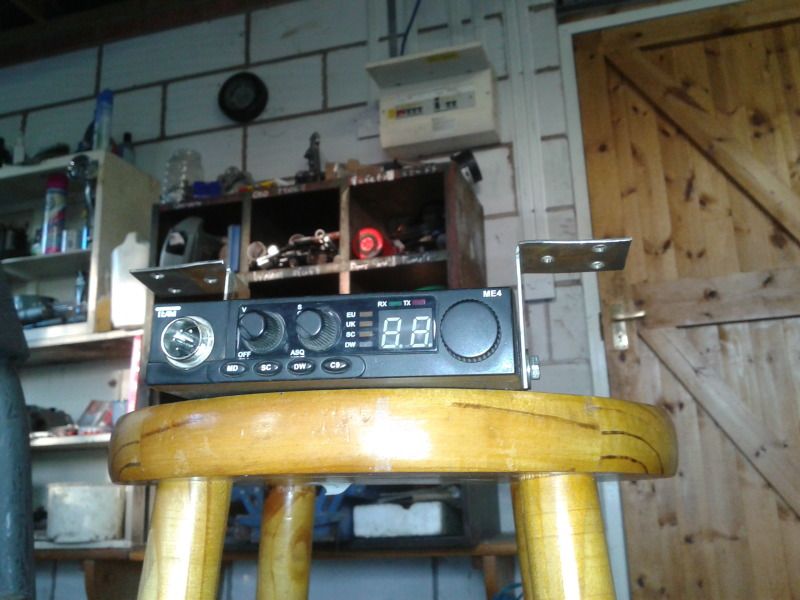
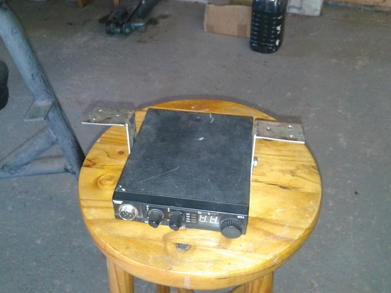
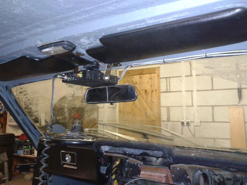
Decision made, I'll not use the CB 99% of the time so roof mounted it is, its out of the way and easy to get to,
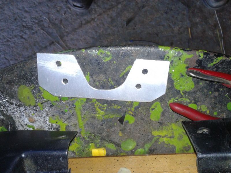
Started off with some SS strips, drilled some holes and cut them to shape.
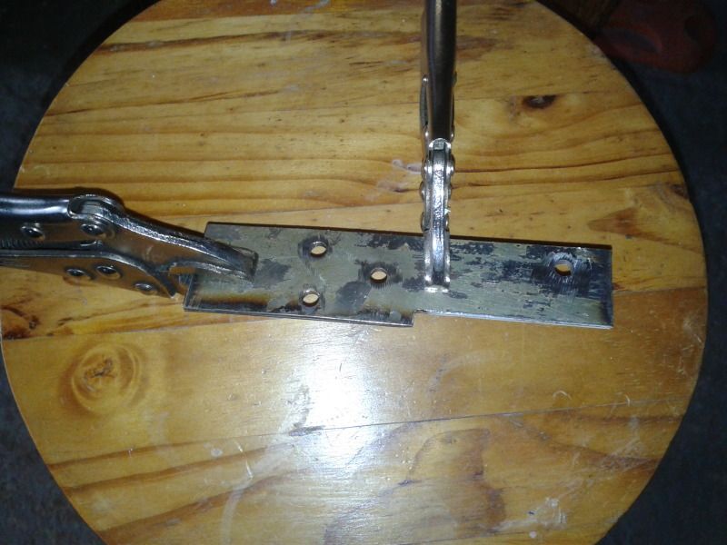
Bent them to an L shape.
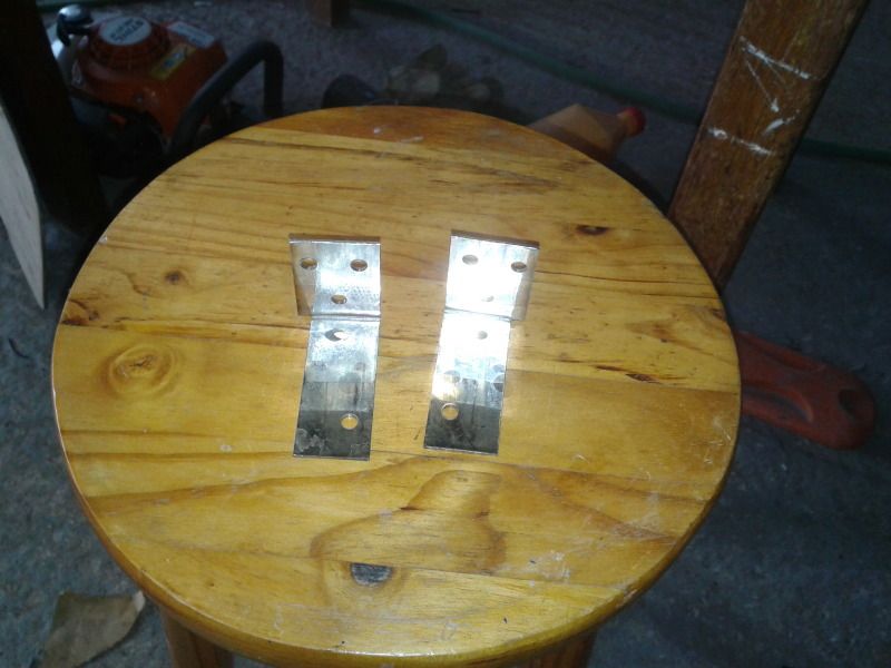
And bolted them to the sides of the radio.
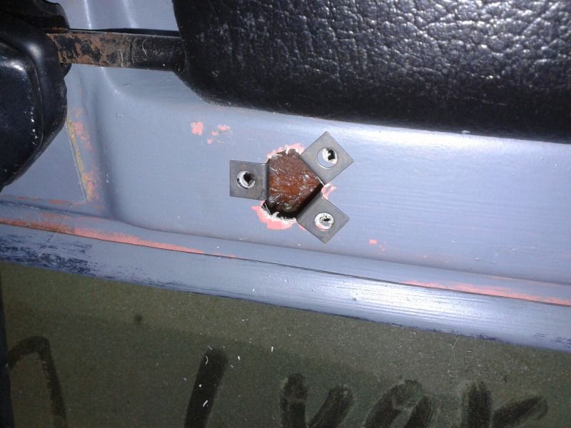
Drilled the little mounting holes in the ceiling, then drilled a much bigger hole between them so that some screw clip fixing things could be used (I've found the GRP to be useless with screws).
Da-da!!!!
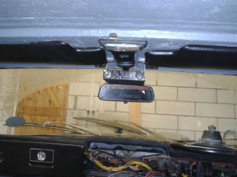
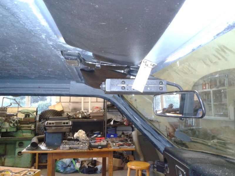
There was still some evening left so I wired it in too and took the wires past the driver sun viser, you should be able to see in the photos.
I even tested it and heard someone somewhere talking
More to come
Started off with some SS strips, drilled some holes and cut them to shape.
Bent them to an L shape.
And bolted them to the sides of the radio.
Drilled the little mounting holes in the ceiling, then drilled a much bigger hole between them so that some screw clip fixing things could be used (I've found the GRP to be useless with screws).
Da-da!!!!
There was still some evening left so I wired it in too and took the wires past the driver sun viser, you should be able to see in the photos.
I even tested it and heard someone somewhere talking
More to come
Made a little strengthening piece this morning as the column surround is falling ot bits.
And found some plugs to fill the holes left by the overdrive switch and an auxilary light of some sort.
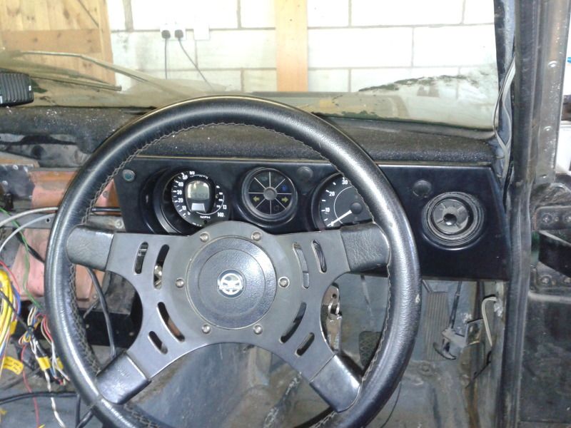
Then mounted the aux light as a fan indicator, and the LPG switch on the left of the dash panel, then screwed it all together
I've yet to get the stalks past this modification, that'll be fun. I've never figured out how to get that assembly together without bending some bits and forcing it in there, wonder how they did it in the factory?
Thats all folks for a bit
And found some plugs to fill the holes left by the overdrive switch and an auxilary light of some sort.
Then mounted the aux light as a fan indicator, and the LPG switch on the left of the dash panel, then screwed it all together
I've yet to get the stalks past this modification, that'll be fun. I've never figured out how to get that assembly together without bending some bits and forcing it in there, wonder how they did it in the factory?
Thats all folks for a bit
An update...
There is lots still to do on the scimitar, but three major jobs remain, the roll hoop needs making (toying with the idea of having that done else where), the diff needs putting in and the rer caliper mounts need making. I tried to tackle the diff at work but we couldn't get the bearings off. This weekend I went to visit an old uni buddy of supra powered capri fame) with a good bearing puller and a height measuring thing and I've nearly ticked diff off that list. Well the difficult part of the job anyway.
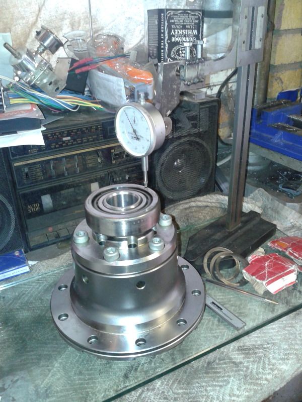
First of all I had to make the extension for the height vernier (i'm not actually sure of its name but this seams like a good name). It has to be quite rigid to give repeatable results. I also drilled a hole to mount a dial guage to it as this job requires a lot of accuracy (you only find zero on the dial guage then measure from the height vernier).
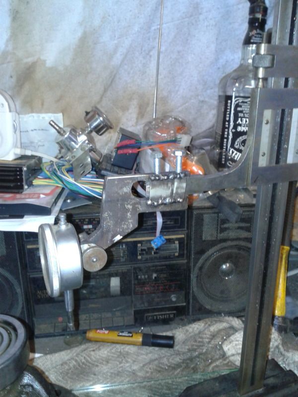
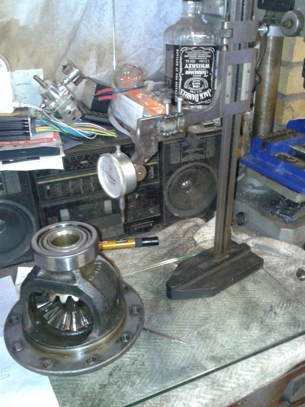
Next the flat glass surface was read off as the zero point (turned out it was easily manipulated so that it was exactly 2.5" up the scale), so this value could be sutracted from all the measurements taken. The the original diff measured with its bearings still on. The base up to the CW mount face was measured and the total height from bearing to bearing was measured.
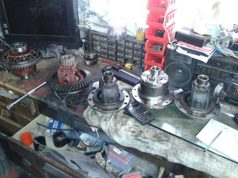
I brought along two open diffs (to choose the best bearings from the set) the quaife and pete also had his open diff about with his powerlock out for a change of CWP, so we had for 5 4HA diffs on the side at one point
Next the Quiafe was measured a millioin times to make sure I was getting it right and it was repeatable, the a load of head scratching and calculations were done, the right thickness of shims put on and the bearing tapped into place, this is the half way point. Then the top bearing was measured to find exactly the thickness of shims needed for the top bearing.
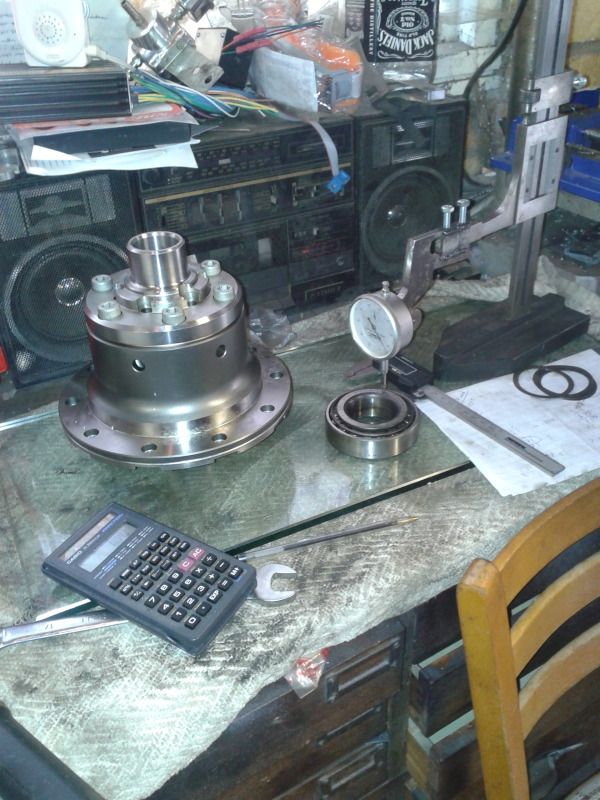
And the final assembly I measured and measured and there was no measurable difference between this and the original diff measurements
TheQuaife neeeded lots of shims on the bottom (over 4mm), and very few on the top, the bearing stub actually sticks out of the top bearing a little so I have to lathe it back a little before it goes in, but I'm really pleased that this job is ticked off.
More to come
There is lots still to do on the scimitar, but three major jobs remain, the roll hoop needs making (toying with the idea of having that done else where), the diff needs putting in and the rer caliper mounts need making. I tried to tackle the diff at work but we couldn't get the bearings off. This weekend I went to visit an old uni buddy of supra powered capri fame) with a good bearing puller and a height measuring thing and I've nearly ticked diff off that list. Well the difficult part of the job anyway.
First of all I had to make the extension for the height vernier (i'm not actually sure of its name but this seams like a good name). It has to be quite rigid to give repeatable results. I also drilled a hole to mount a dial guage to it as this job requires a lot of accuracy (you only find zero on the dial guage then measure from the height vernier).
Next the flat glass surface was read off as the zero point (turned out it was easily manipulated so that it was exactly 2.5" up the scale), so this value could be sutracted from all the measurements taken. The the original diff measured with its bearings still on. The base up to the CW mount face was measured and the total height from bearing to bearing was measured.
I brought along two open diffs (to choose the best bearings from the set) the quaife and pete also had his open diff about with his powerlock out for a change of CWP, so we had for 5 4HA diffs on the side at one point
Next the Quiafe was measured a millioin times to make sure I was getting it right and it was repeatable, the a load of head scratching and calculations were done, the right thickness of shims put on and the bearing tapped into place, this is the half way point. Then the top bearing was measured to find exactly the thickness of shims needed for the top bearing.
And the final assembly I measured and measured and there was no measurable difference between this and the original diff measurements
TheQuaife neeeded lots of shims on the bottom (over 4mm), and very few on the top, the bearing stub actually sticks out of the top bearing a little so I have to lathe it back a little before it goes in, but I'm really pleased that this job is ticked off.
More to come
Gassing Station | Scimitar | Top of Page | What's New | My Stuff