Tamiya 1:12 McLaren MP4/6 Rebuild/Upgrade
Discussion


Painted the fuel rails Vallejo steel, and gave the crevices a very light wash followed by light gunmetal Tamiya powder. The larger the scale, the less highlighting is needed, especially on a racing car. Then assembled to the inlet ducts. There are 24 fuel injectors, and each has a cover plate from the T/S set, which I painted satin black as per my references. Attached with PVA:

Each one now needs its electrical connector fitting, and associated wiring. I’ve temporarily assembled the heads and rails to figure out the best orientation for these:

Each one now needs its electrical connector fitting, and associated wiring. I’ve temporarily assembled the heads and rails to figure out the best orientation for these:
Before the T/S sets became available for these models, I’d bought some Formula Perfect stuff, including the turned trumpets and resin tray. There was also an extensive pre-cut p/e set:

There’s one slight bubble in the resin tray that needs addressing, then it’ll be ready for some satin black and the first of the carbon decals.
There’s one slight bubble in the resin tray that needs addressing, then it’ll be ready for some satin black and the first of the carbon decals.
Hmmm. I temporarily assembled the FP trumpets in their tray, but they dont look right to me. The spacing is too much, and there is no radius on the edges:

Here's the real thing:

And the TS version, which I think is slightly better:

Although ironically, the original kit items are probably the closest in terms of spacing, but they're obviously plasticky and lack the surface realism of turned parts:

Net result - I've ordered the TS versions. For less than £20, didn't seem worth the compromise.
Here's the real thing:
And the TS version, which I think is slightly better:
Although ironically, the original kit items are probably the closest in terms of spacing, but they're obviously plasticky and lack the surface realism of turned parts:
Net result - I've ordered the TS versions. For less than £20, didn't seem worth the compromise.
With the inlets on hold, I continued with building up some other stuff:
The jack plates and a.r.b. Brackets are made up of laminated p/e, to simulate cnc’d plate. There’s also a base plate for the oil catch tank. There was a lot of residue from the plastic backing on these parts, easily removed with enamel thinners:

Considered soldering, but in the end went for thin cyano, wicked into the corners with some fuse wire (sanded to make the glue cling to it better. I lightly sanded the mating faces for better wetting. I also applied cyano around the periphery of the parts and sanded it back, to eliminate the mating line:

Cleaned off any excess with a blade and fibreglass pencil, and ready for priming:
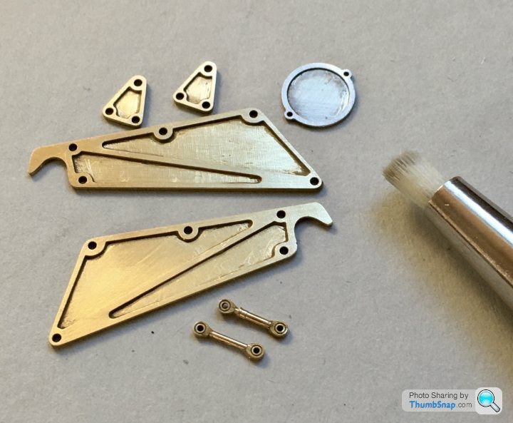
The a.r.b. links are turned brass, with two part rose joints on each end. I assembled these with Araldite:

All primed and ready for a dry assembly run:

The jack plates and a.r.b. Brackets are made up of laminated p/e, to simulate cnc’d plate. There’s also a base plate for the oil catch tank. There was a lot of residue from the plastic backing on these parts, easily removed with enamel thinners:
Considered soldering, but in the end went for thin cyano, wicked into the corners with some fuse wire (sanded to make the glue cling to it better. I lightly sanded the mating faces for better wetting. I also applied cyano around the periphery of the parts and sanded it back, to eliminate the mating line:
Cleaned off any excess with a blade and fibreglass pencil, and ready for priming:
The a.r.b. links are turned brass, with two part rose joints on each end. I assembled these with Araldite:
All primed and ready for a dry assembly run:
This is the rear a.r.b. Assembly. A lot of it is pinned together with brass rod you have to laboriously cut and file to length. To be correct you then have to glue a false fastener head on the end. Would have been easier to use nut studs, but there were go:

The brackets are fitted in the same way to the gearbox casing, but the holes are different sizes. I’ve made plastic spigots instead:
Ditto for the jack bracket:

It’ll all look much better when it’s properly painted.
The brackets are fitted in the same way to the gearbox casing, but the holes are different sizes. I’ve made plastic spigots instead:
Ditto for the jack bracket:
It’ll all look much better when it’s properly painted.
generationx said:
Hi Doc
The quality of work and the patience displayed is just humbling!
This thread is my daily pleasure and where I direct friends/colleagues if they starting saying things like "oh they're just toys".
Marvellous.
Thanks! I was hoping to keep progress up, but today started with a cold. At least I hope it's just a cold!The quality of work and the patience displayed is just humbling!
This thread is my daily pleasure and where I direct friends/colleagues if they starting saying things like "oh they're just toys".
Marvellous.
Stay safe everyone.
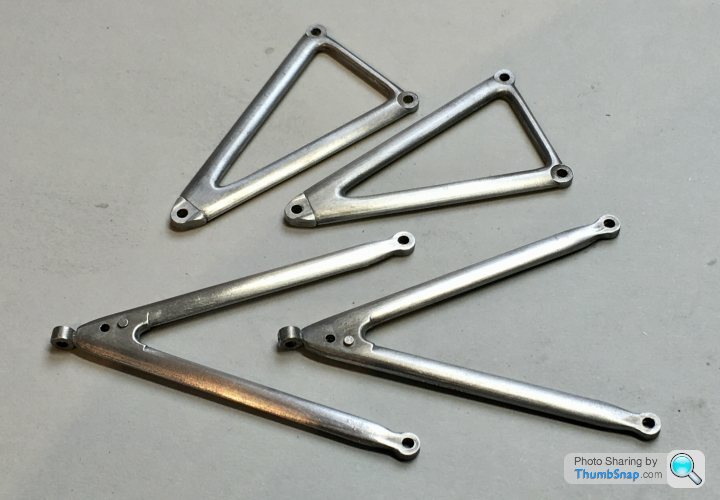
The rear pushrods and track-control arms are resin items supplied in the T/S set. Reason is that the ends are far more detailed, with rose joints and lock nuts. The turned brass spigots fit into the ends of each arm; the original white metal arms would be difficult to prepare like this:

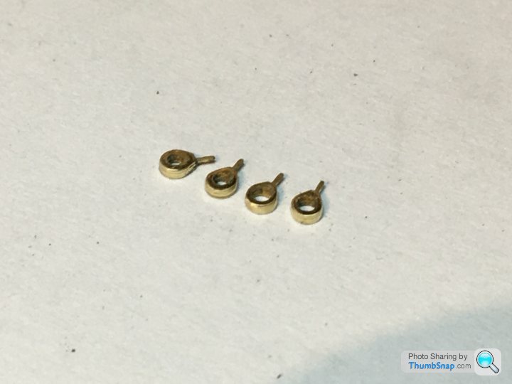
The Rose joints are laminated from three brass profiles. I Araldited these together:

Obviously in reality they are solid metal, so I tried to blend the laminations with Micro mesh pads:

Much better:
Another small bit done:

The Rose joints are laminated from three brass profiles. I Araldited these together:
Obviously in reality they are solid metal, so I tried to blend the laminations with Micro mesh pads:
Much better:
Another small bit done:

uncleluck said:
Amazing stuff, very impressive.
Do you ever wake screaming from a nightmare where you walk into the lounge & a young relative is making brum brum noises while banging it up against the skirting board?
I was going to build my Tamiya R32 GTR, think I’ll pop it back in the cupboard after seeing this.
Thanks! No, the kids are used to it now, plus my son started building & painting figures, so he knows how much effort it takes.Do you ever wake screaming from a nightmare where you walk into the lounge & a young relative is making brum brum noises while banging it up against the skirting board?
I was going to build my Tamiya R32 GTR, think I’ll pop it back in the cupboard after seeing this.
Is the R32 a 1:24 kit? They usually build up beautifully with no aftermarket. If you don’t make a start you’ll never know!

Still figuring out where additional fastener holes need drilling. A lot aren’t in the T/S set, which is surprising. Some of the parts within the set itself have missing holes/bolts, like the resin rear suspension brackets. The fasteners I’m adding here are RB Motion stud & nut pins. I’ve added washers behind the engine/gearbox joint items to make them look more substantial. The lighter stuff like the pipe flange won’t have washers:


Painted the engine block and gearbox components:

Unfortunately, some suspension mounts are sandwiched between parts, the joint lines then need filling:

Flatting and re-painting those will be fun.
Also decided to give the gearbox castings a dark wash - they look too flat. It’ll Bev very light, since I don’t want any weathering, just to give a bit of depth.
Unfortunately, some suspension mounts are sandwiched between parts, the joint lines then need filling:
Flatting and re-painting those will be fun.
Also decided to give the gearbox castings a dark wash - they look too flat. It’ll Bev very light, since I don’t want any weathering, just to give a bit of depth.
I flatted the casing filler with chopped down sanding sticks & sponges and finished with a fibreglass pencil:

Then masked the suspension mount ready for re-spraying:

Then masked the casing again and re-did the mount:

Pain in the arse, but the casing looks far more like a one-piece casting - especially around the triangular engine mounts, which had a big gap at their ends:

Everything’s been given a coat of Klear ready for a light wash.
Then masked the suspension mount ready for re-spraying:
Then masked the casing again and re-did the mount:
Pain in the arse, but the casing looks far more like a one-piece casting - especially around the triangular engine mounts, which had a big gap at their ends:
Everything’s been given a coat of Klear ready for a light wash.
A few low-level bits of modelling and some frustrations over the past few days.
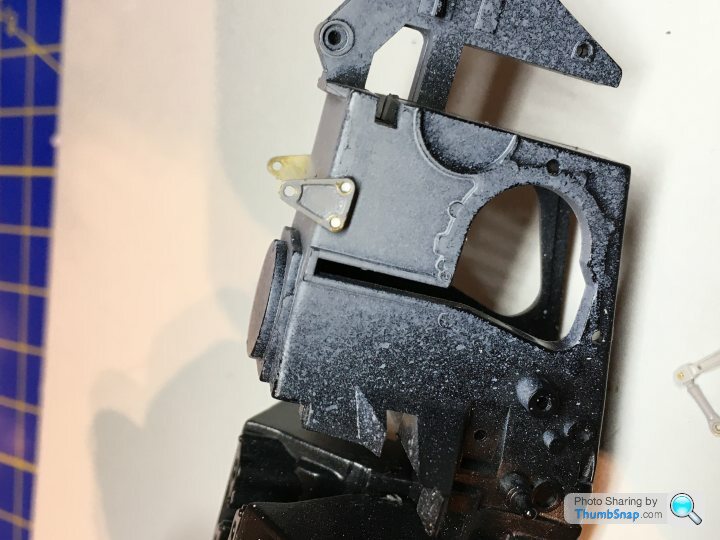
The frustration was that the Top Studio detail set instructs you to remove the moulded-in ring on top of the gearbox housing (original Tamiya assembly shown below, modified above):

I did this without thinking too much about it, because I assumed the original Tamiya moulding was incorrect, and that the ring was supposed to be a mounting for the small oil tank, but it was too far forward. I also assumed that the Top Studio replacement oil tank and photo-etch base was meant to fit like this:

...but having lookead at reference photos, the Tamiya moulding is in fact correct:

I think that Top Studio may have made a mistake - the original Tamiya detail should have been retained, and the photo-etch should have been a base with a pair of 'mickey mouse' ears, offset forward, to mate up with the lugs on the original moulding.
Anyway, I'm now stuck with replacing the perfectly good, but removed plastic, with the photo-etch. After confirming that the circular item is a black cover plate on the F1M questions forum, I’ve ended up with this (still needs detailing obviously):

I also added various sized rivets to represent the engine block core and oil gallery plugs:


Also visible are the pipe union nut and stud pins.
Added some more fastener heads to the intake flanges:

Finally, finished detailing the starter gear/gear selector extension for the gearbox:

Ideally I’d have added lock wires to the face plate bolts on that, but couldn’t find anything fine enough.
The frustration was that the Top Studio detail set instructs you to remove the moulded-in ring on top of the gearbox housing (original Tamiya assembly shown below, modified above):
I did this without thinking too much about it, because I assumed the original Tamiya moulding was incorrect, and that the ring was supposed to be a mounting for the small oil tank, but it was too far forward. I also assumed that the Top Studio replacement oil tank and photo-etch base was meant to fit like this:
...but having lookead at reference photos, the Tamiya moulding is in fact correct:
I think that Top Studio may have made a mistake - the original Tamiya detail should have been retained, and the photo-etch should have been a base with a pair of 'mickey mouse' ears, offset forward, to mate up with the lugs on the original moulding.
Anyway, I'm now stuck with replacing the perfectly good, but removed plastic, with the photo-etch. After confirming that the circular item is a black cover plate on the F1M questions forum, I’ve ended up with this (still needs detailing obviously):
I also added various sized rivets to represent the engine block core and oil gallery plugs:
Also visible are the pipe union nut and stud pins.
Added some more fastener heads to the intake flanges:
Finally, finished detailing the starter gear/gear selector extension for the gearbox:
Ideally I’d have added lock wires to the face plate bolts on that, but couldn’t find anything fine enough.
Gassing Station | Scale Models | Top of Page | What's New | My Stuff