Tamiya 1:12 McLaren MP4/6 Rebuild/Upgrade
Discussion


CanAm said:
dr_gn said:
Ideally I’d have added lock wires to the face plate bolts on that, but couldn’t find anything fine enough.
There has to be a time when you have to stand back and think, "Whoa, am I going too far?"But if you insist, would some silver hair be of assistance? I've got plenty.


The thinnest wire I had was 0.2 mm stainless. Twisted in a pin vice it looks like this:

Looks about 2x too thick.
If I assume 0.7 mm wire on the real car, that scales to about 0.06 mm. Hair is about 0.03 mm, so too thin (and a nightmare to twist).
I’ve tried twisting a single strand of 0.2, but you can’t see the twists. Lead wire breaks.
I'm sure you can get 0.06 mm wire, but I don't need km's of it. I'll have to have a look in my electrical stores and see if I can unwind some fillament of something or other.
Edited by dr_gn on Friday 10th April 10:20

Toma500 said:
You could try stripping back some wire from a standard electric cable itll be copper but much smaller diameter
Thanks, I want stainless really. I think the braiding from an iphone charger cable might work. I've got some electrical bits and pieces in the garage, I'm sure I'll find something.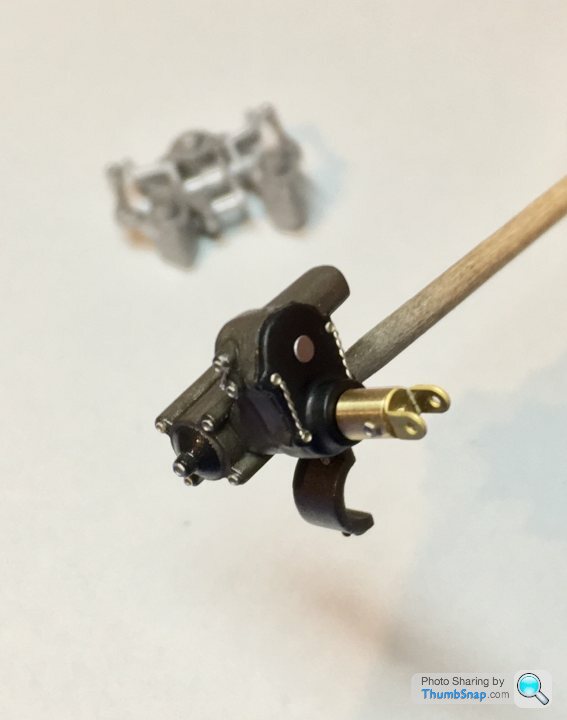

Started by removing all the moulded-in fasteners, and removing the clunky plastic linkages and replacing them with resin rod ends and wire. I think the rod-ends are intended for the floor stays, but there are some spares luckily:

I might re-position the upper links on more realistic levers.
I might re-position the upper links on more realistic levers.
Edited by dr_gn on Friday 10th April 22:24
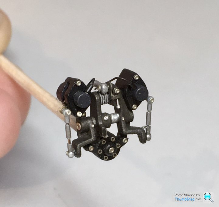
Ended up removing the levers and pocketing the potentiometer extensions (one fell off, but no big deal) using drills, blades and chisels.

Then inserted some stubs of aluminium tube to represent the butterfly spindle extensions. I’ll make some new levers from scrap photo-etch.

It’ll be a compromise because it’s a complex assembly, but better than the original.
Then inserted some stubs of aluminium tube to represent the butterfly spindle extensions. I’ll make some new levers from scrap photo-etch.
It’ll be a compromise because it’s a complex assembly, but better than the original.


That’s about as far as I’m going with the throttle linkage/position sensors:

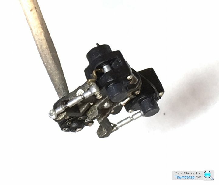
The basics of what’s there is in place, but the true complexity isn’t. Added a return spring out of lead wire, turnbuckles from brass tube, resin rod ends, p/e bolt heads and an RB motion bolt for the main clamp.
Waiting for some Tamiya semi-gloss clear to normalise the finish of everything and take the shine off the fasteners a bit.
Edited by dr_gn on Monday 13th April 17:13
p4cks said:
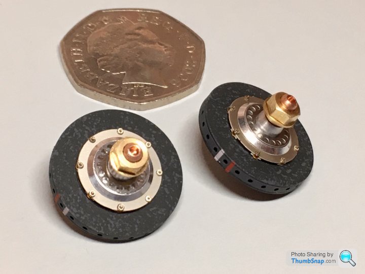
I was amazed at the detail in the gearbox so I showed my GF the photo of it on its own and said this fella on PH makes his own <size not mentioned> car parts, and it received an approving nod. Then I showed her the photo of it sitting on a 50p piece and she was gobsmacked!
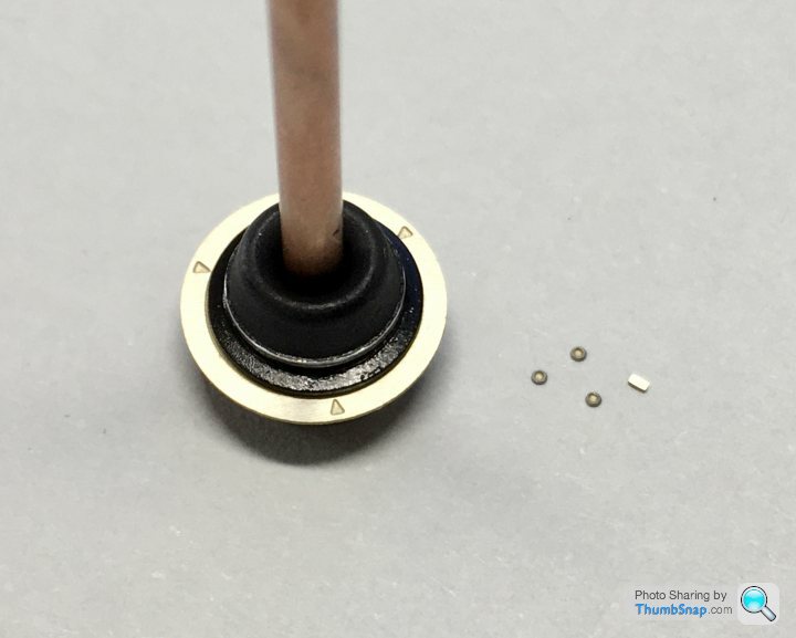
Thanks, but it’s actually just a huge 50pBit of a simple job this morning: driveshafts. The TS items are turned, and anodised to the perfect colour:
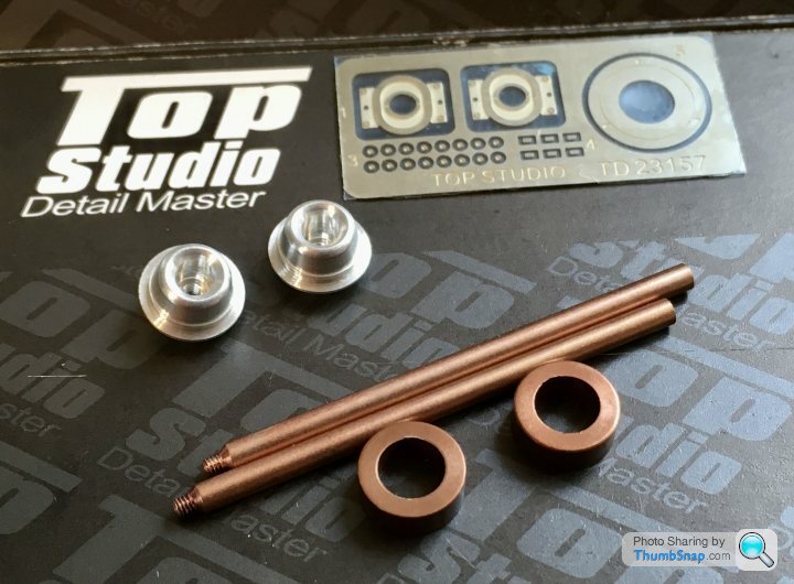
It’s a shame the turned aluminium cv joints and boots need to be painted, but some semi gloss black and rubber black made them look more realistic. I then scraped the paint off the raised ring to represent the boot clamp:

The larger bits of etch represent the split plates that fit on the carbon fibre brake ducts at the wheel ends of the shafts.
There’s a neat little jig in the p/e fret so you can get the bolt heads spaced at exactly 120 degrees:
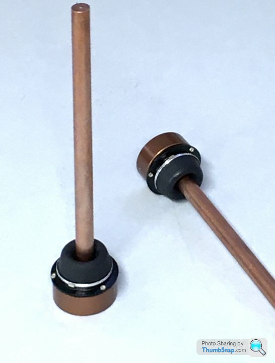
Added the p/e clamp ring crimped ends, and it’s job done apart from some satin clear:
It’s a shame the turned aluminium cv joints and boots need to be painted, but some semi gloss black and rubber black made them look more realistic. I then scraped the paint off the raised ring to represent the boot clamp:
The larger bits of etch represent the split plates that fit on the carbon fibre brake ducts at the wheel ends of the shafts.
There’s a neat little jig in the p/e fret so you can get the bolt heads spaced at exactly 120 degrees:
Added the p/e clamp ring crimped ends, and it’s job done apart from some satin clear:
Edited by dr_gn on Tuesday 14th April 12:01
ajprice said:
dr_gn said:
p4cks said:
I was amazed at the detail in the gearbox so I showed my GF the photo of it on its own and said this fella on PH makes his own <size not mentioned> car parts, and it received an approving nod. Then I showed her the photo of it sitting on a 50p piece and she was gobsmacked!
Thanks, but it’s actually just a huge 50p

I’m beginning to lose track of where everything is. I’ve got the original engine for reference, the new Tamiya engine parts, the Top Studio engine, intake and brake sets, and individual bits and pieces, RB motion fasteners, Formula Perfect parts (some of which are duplicated for some reason), and some random wiring and pipe work:

...plus a container for the more intricate completed parts:
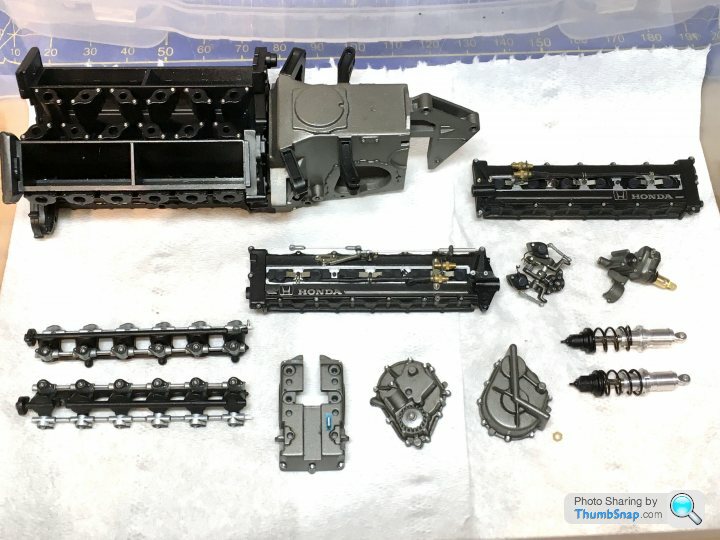
And that’s before any work on the monocoque, cockpit and front suspension.
...plus a container for the more intricate completed parts:
And that’s before any work on the monocoque, cockpit and front suspension.
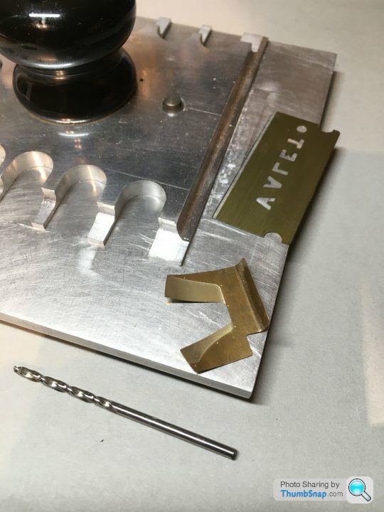
Needed a break from the engine, so started on the rear uprights. First off, the duct covers needed bending to match the curve of the ducts, and 90 degree bends applying. I annealed them first over a candle, to make them less springy:
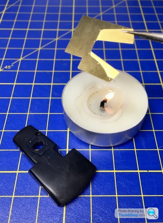
My home-made p/e bender was pressed into service again:
Result is a decent fit- just needs cyano‘ing into place. There was also a prominent ejector pin mark inside the duct that I filled with Tamiya filler:
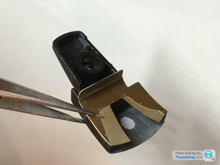
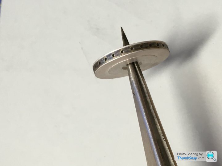
Put them to one side for finishing, then moved on to the brakes. First off, annealed the circumferential p/e with the cooling holes:
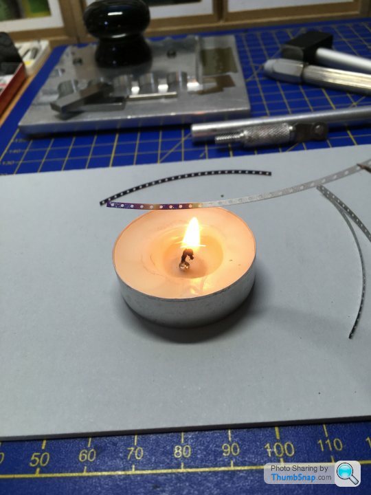
Then drew a scalpel handle back and forth over the strips to give them the right curve:
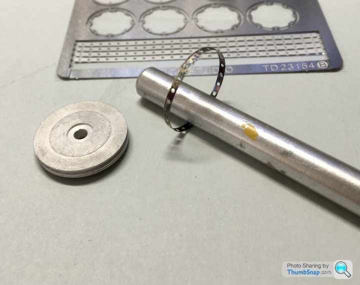
Test-fitted to a white metal disc:
Sorted:

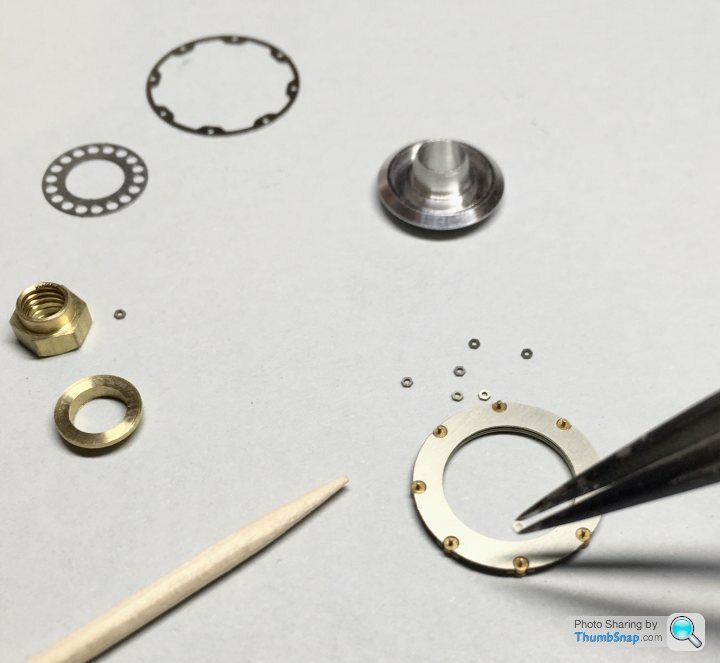
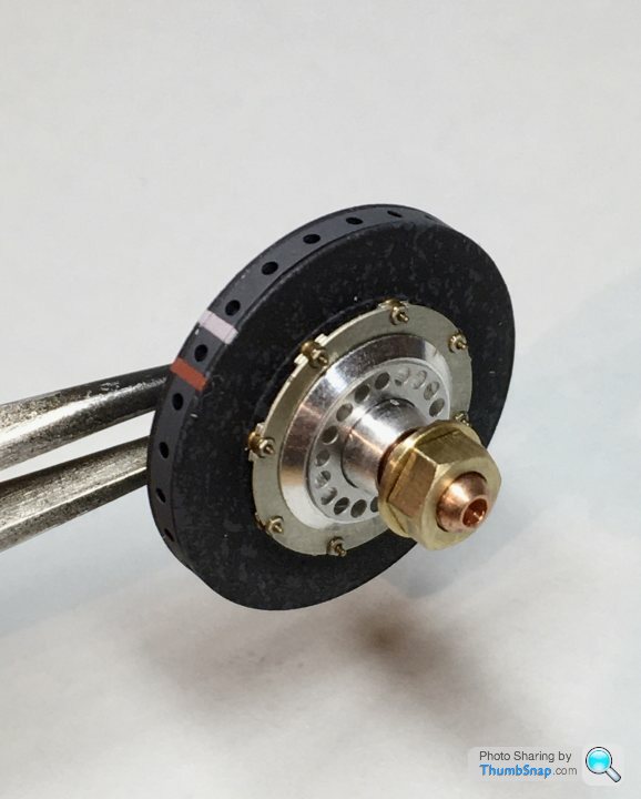
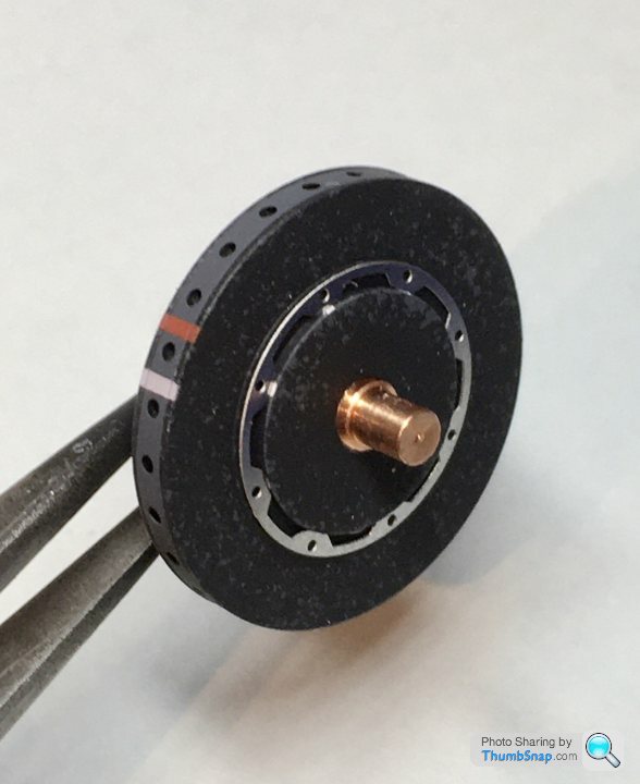
Then the floating rotor bells, stub axles and wheel nuts. These are most of the components for one corner:
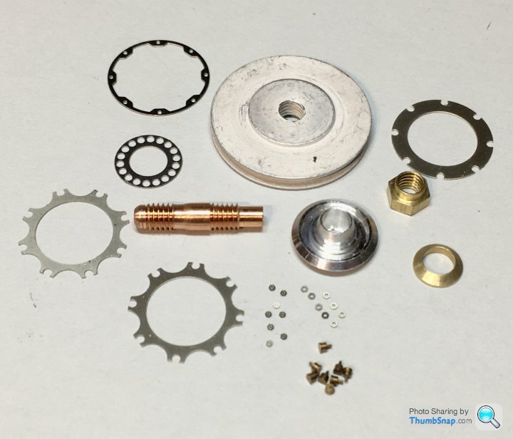
Superb components, and a dry run seems to indicate they will fit together perfectly. Which is nice.
My home-made p/e bender was pressed into service again:
Result is a decent fit- just needs cyano‘ing into place. There was also a prominent ejector pin mark inside the duct that I filled with Tamiya filler:
Put them to one side for finishing, then moved on to the brakes. First off, annealed the circumferential p/e with the cooling holes:
Then drew a scalpel handle back and forth over the strips to give them the right curve:
Test-fitted to a white metal disc:
Sorted:
Then the floating rotor bells, stub axles and wheel nuts. These are most of the components for one corner:
Superb components, and a dry run seems to indicate they will fit together perfectly. Which is nice.
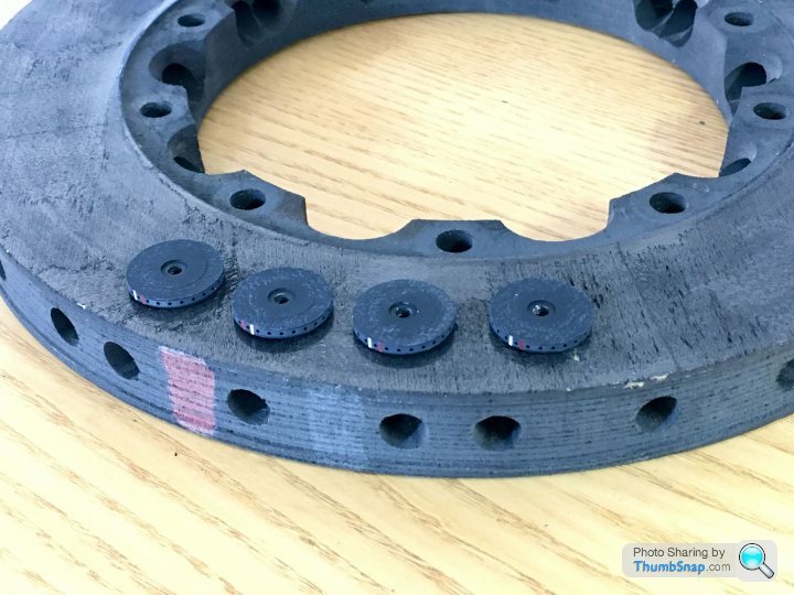
Attention turned to the carbon/carbon composite rotors. I happen to have a couple of F1 items on the wall in my garage:

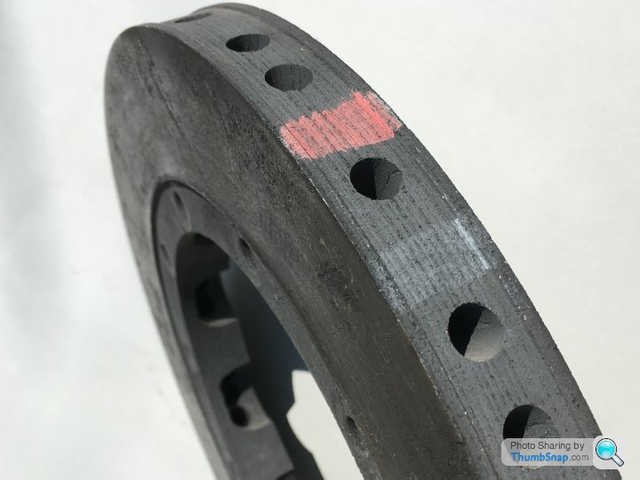
The surfaces are heavily pitted, and consist of a series of randomly orientsted plates - a bit like galvanised steel, but black. Multiple shades of black and grey, all of which reflect light to different degrees. Tricky to reproduce. Also, the circumference is a lighter colour, and there are red and white markings across the edges.
I started by cleaning the oxidisation of the white metal surfaces with a fibreglass pencil, and primed with Tamiya grey. Then applied NATO black overall, followed by dark grey applied with a sponge:

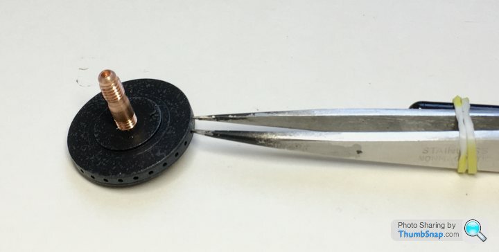
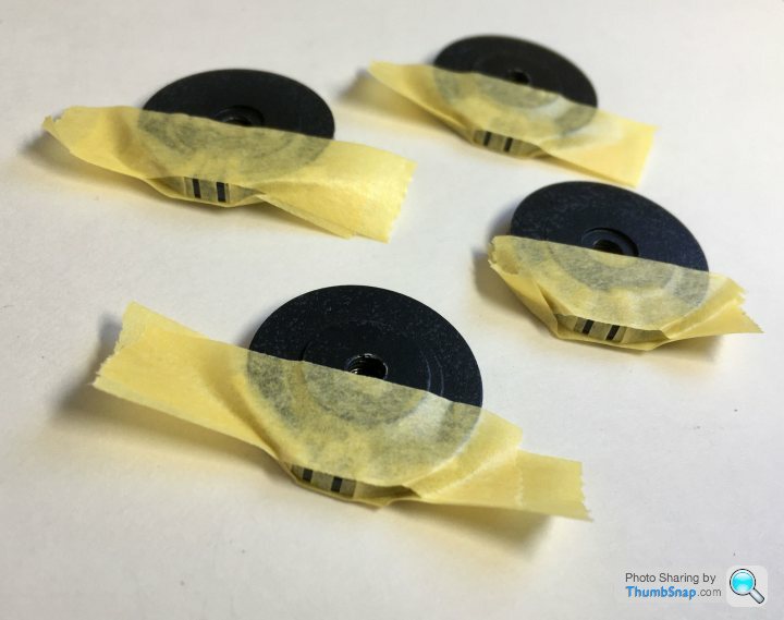
The cooling hole bands were painted dark grey and secured with PVA at the join. These were held tightly in place with tweezers sprung shut with a loom band:
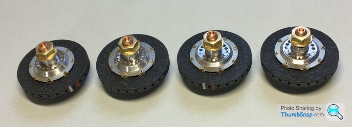
Then masked for the markings to be applied with the airbrush:
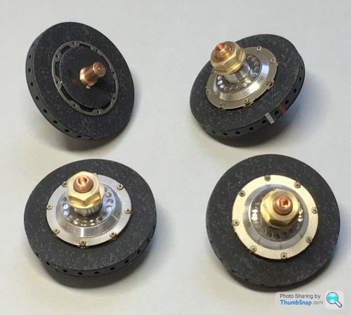
Masking removed, and a coat of Matt:
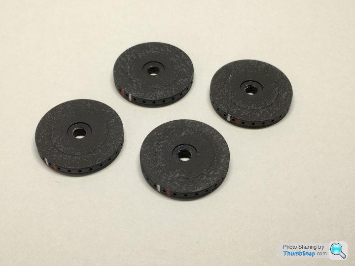
Next is to assemble the stub axles and bells to them
The surfaces are heavily pitted, and consist of a series of randomly orientsted plates - a bit like galvanised steel, but black. Multiple shades of black and grey, all of which reflect light to different degrees. Tricky to reproduce. Also, the circumference is a lighter colour, and there are red and white markings across the edges.
I started by cleaning the oxidisation of the white metal surfaces with a fibreglass pencil, and primed with Tamiya grey. Then applied NATO black overall, followed by dark grey applied with a sponge:
The cooling hole bands were painted dark grey and secured with PVA at the join. These were held tightly in place with tweezers sprung shut with a loom band:
Then masked for the markings to be applied with the airbrush:
Masking removed, and a coat of Matt:
Next is to assemble the stub axles and bells to them
Edited by dr_gn on Thursday 16th April 16:07
Halmyre said:
dr_gn said:
Halmyre said:
dr_gn said:
I suppose it's too late to point out that the spacing of the holes round the rim aren't the same as the photo-etch?
This one is though:


I'm simply aiming for "a 1991 McLaren MP4/6", as I remember them 'in the flesh'.
Gassing Station | Scale Models | Top of Page | What's New | My Stuff