Tamiya 1:12 McLaren MP4/6 Rebuild/Upgrade
Discussion


Amazing stuff, very impressive.
Do you ever wake screaming from a nightmare where you walk into the lounge & a young relative is making brum brum noises while banging it up against the skirting board?
I was going to build my Tamiya R32 GTR, think I’ll pop it back in the cupboard after seeing this.
Do you ever wake screaming from a nightmare where you walk into the lounge & a young relative is making brum brum noises while banging it up against the skirting board?
I was going to build my Tamiya R32 GTR, think I’ll pop it back in the cupboard after seeing this.
uncleluck said:
Amazing stuff, very impressive.
Do you ever wake screaming from a nightmare where you walk into the lounge & a young relative is making brum brum noises while banging it up against the skirting board?
I was going to build my Tamiya R32 GTR, think I’ll pop it back in the cupboard after seeing this.
Thanks! No, the kids are used to it now, plus my son started building & painting figures, so he knows how much effort it takes.Do you ever wake screaming from a nightmare where you walk into the lounge & a young relative is making brum brum noises while banging it up against the skirting board?
I was going to build my Tamiya R32 GTR, think I’ll pop it back in the cupboard after seeing this.
Is the R32 a 1:24 kit? They usually build up beautifully with no aftermarket. If you don’t make a start you’ll never know!

Still figuring out where additional fastener holes need drilling. A lot aren’t in the T/S set, which is surprising. Some of the parts within the set itself have missing holes/bolts, like the resin rear suspension brackets. The fasteners I’m adding here are RB Motion stud & nut pins. I’ve added washers behind the engine/gearbox joint items to make them look more substantial. The lighter stuff like the pipe flange won’t have washers:


Painted the engine block and gearbox components:

Unfortunately, some suspension mounts are sandwiched between parts, the joint lines then need filling:

Flatting and re-painting those will be fun.
Also decided to give the gearbox castings a dark wash - they look too flat. It’ll Bev very light, since I don’t want any weathering, just to give a bit of depth.
Unfortunately, some suspension mounts are sandwiched between parts, the joint lines then need filling:
Flatting and re-painting those will be fun.
Also decided to give the gearbox castings a dark wash - they look too flat. It’ll Bev very light, since I don’t want any weathering, just to give a bit of depth.
I flatted the casing filler with chopped down sanding sticks & sponges and finished with a fibreglass pencil:

Then masked the suspension mount ready for re-spraying:

Then masked the casing again and re-did the mount:

Pain in the arse, but the casing looks far more like a one-piece casting - especially around the triangular engine mounts, which had a big gap at their ends:

Everything’s been given a coat of Klear ready for a light wash.
Then masked the suspension mount ready for re-spraying:
Then masked the casing again and re-did the mount:
Pain in the arse, but the casing looks far more like a one-piece casting - especially around the triangular engine mounts, which had a big gap at their ends:
Everything’s been given a coat of Klear ready for a light wash.
A few low-level bits of modelling and some frustrations over the past few days.
The frustration was that the Top Studio detail set instructs you to remove the moulded-in ring on top of the gearbox housing (original Tamiya assembly shown below, modified above):

I did this without thinking too much about it, because I assumed the original Tamiya moulding was incorrect, and that the ring was supposed to be a mounting for the small oil tank, but it was too far forward. I also assumed that the Top Studio replacement oil tank and photo-etch base was meant to fit like this:

...but having lookead at reference photos, the Tamiya moulding is in fact correct:

I think that Top Studio may have made a mistake - the original Tamiya detail should have been retained, and the photo-etch should have been a base with a pair of 'mickey mouse' ears, offset forward, to mate up with the lugs on the original moulding.
Anyway, I'm now stuck with replacing the perfectly good, but removed plastic, with the photo-etch. After confirming that the circular item is a black cover plate on the F1M questions forum, I’ve ended up with this (still needs detailing obviously):

I also added various sized rivets to represent the engine block core and oil gallery plugs:


Also visible are the pipe union nut and stud pins.
Added some more fastener heads to the intake flanges:

Finally, finished detailing the starter gear/gear selector extension for the gearbox:

Ideally I’d have added lock wires to the face plate bolts on that, but couldn’t find anything fine enough.
The frustration was that the Top Studio detail set instructs you to remove the moulded-in ring on top of the gearbox housing (original Tamiya assembly shown below, modified above):
I did this without thinking too much about it, because I assumed the original Tamiya moulding was incorrect, and that the ring was supposed to be a mounting for the small oil tank, but it was too far forward. I also assumed that the Top Studio replacement oil tank and photo-etch base was meant to fit like this:
...but having lookead at reference photos, the Tamiya moulding is in fact correct:
I think that Top Studio may have made a mistake - the original Tamiya detail should have been retained, and the photo-etch should have been a base with a pair of 'mickey mouse' ears, offset forward, to mate up with the lugs on the original moulding.
Anyway, I'm now stuck with replacing the perfectly good, but removed plastic, with the photo-etch. After confirming that the circular item is a black cover plate on the F1M questions forum, I’ve ended up with this (still needs detailing obviously):
I also added various sized rivets to represent the engine block core and oil gallery plugs:
Also visible are the pipe union nut and stud pins.
Added some more fastener heads to the intake flanges:
Finally, finished detailing the starter gear/gear selector extension for the gearbox:
Ideally I’d have added lock wires to the face plate bolts on that, but couldn’t find anything fine enough.
CanAm said:
dr_gn said:
Ideally I’d have added lock wires to the face plate bolts on that, but couldn’t find anything fine enough.
There has to be a time when you have to stand back and think, "Whoa, am I going too far?"But if you insist, would some silver hair be of assistance? I've got plenty.


The thinnest wire I had was 0.2 mm stainless. Twisted in a pin vice it looks like this:

Looks about 2x too thick.
If I assume 0.7 mm wire on the real car, that scales to about 0.06 mm. Hair is about 0.03 mm, so too thin (and a nightmare to twist).
I’ve tried twisting a single strand of 0.2, but you can’t see the twists. Lead wire breaks.
I'm sure you can get 0.06 mm wire, but I don't need km's of it. I'll have to have a look in my electrical stores and see if I can unwind some fillament of something or other.
Edited by dr_gn on Friday 10th April 10:20

Toma500 said:
You could try stripping back some wire from a standard electric cable itll be copper but much smaller diameter
Thanks, I want stainless really. I think the braiding from an iphone charger cable might work. I've got some electrical bits and pieces in the garage, I'm sure I'll find something.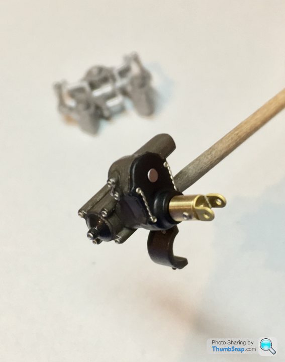

Started by removing all the moulded-in fasteners, and removing the clunky plastic linkages and replacing them with resin rod ends and wire. I think the rod-ends are intended for the floor stays, but there are some spares luckily:

I might re-position the upper links on more realistic levers.
I might re-position the upper links on more realistic levers.
Edited by dr_gn on Friday 10th April 22:24
Ended up removing the levers and pocketing the potentiometer extensions (one fell off, but no big deal) using drills, blades and chisels.

Then inserted some stubs of aluminium tube to represent the butterfly spindle extensions. I’ll make some new levers from scrap photo-etch.

It’ll be a compromise because it’s a complex assembly, but better than the original.
Then inserted some stubs of aluminium tube to represent the butterfly spindle extensions. I’ll make some new levers from scrap photo-etch.
It’ll be a compromise because it’s a complex assembly, but better than the original.


Gassing Station | Scale Models | Top of Page | What's New | My Stuff