Red Bull flexi front wing - judge for yourself
Discussion


As regards the FIA test, where is the 500N (50kg) load actually placed during the test? If the load is placed at the midpoint of the wing it will only be simulating a uniform loading. Now as there are many winglets, in reality, a greater proportion of downforce is created at the wingtip which due to being the furthest point from the wings point of fixation can result in more bending.
stevesingo said:
dr_gn said:
stevesingo said:
My 3 year old son's theory (Honest) is pretty simple. If the wing is tested only on one side at a time then you can easily make each side independently rigid, but allow flex in unison by interlocking the two sides.
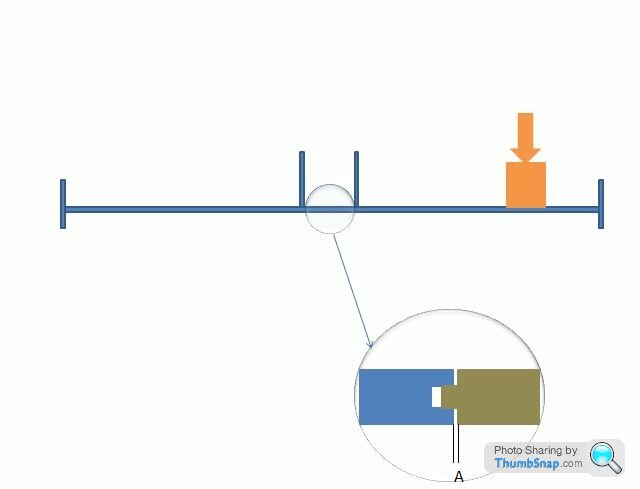
Dimension A could be adjusted to limit the droop as A comes under compression.
Not bad for a 3 year old.
That doesn't make any sense. How does applying load to one side result in more rigidity? Given enough load, the gap would partially or completely close however the wing was loaded.Dimension A could be adjusted to limit the droop as A comes under compression.
Not bad for a 3 year old.
If the wing is split in two sections, LH/RH joined in the middle with such a device as illustrated, when the test is applied to one side (LH of car in this instance) the wing will want to pivot around the fulcrum (LH pylon) applying torque to that fulcrum. In doing so the LH portion is linked to the RH, therefore transferring some of the load to the fulcrum of the RH pylon wing interface (at a much lower leverage), thus, spreading some of the load to the RH pylon and deflecting less. When both sides of the wing are loaded equally, both sides deflect equally and no load is transferred to the opposite side.
When loaded equally, because there is no transfer of load from one side to the other, both side of the wing will droop, but only until the gap "A" becomes zero and "A" comes under compression.
Pat Pending
Steve
You seem to be saying that there is bending around the wing/pylon interface, yet not around the pylon/nose interface. Bending at the pylon/nose interface has the effect (assuming the whole thing didn't jam) of moving the entire L/H wing half in an clockwise arc (looking at your diagram), closing the gap and causing even more deflection than a solid centre section.
Or have I misunderstood the concept?
sjn2004 said:
As regards the FIA test, where is the 500N (50kg) load actually placed during the test? If the load is placed at the midpoint of the wing it will only be simulating a uniform loading. Now as there are many winglets, in reality, a greater proportion of downforce is created at the wingtip which due to being the furthest point from the wings point of fixation can result in more bending.
From page 1The rule:
3.17.1 Bodywork may deflect no more than 10mm vertically when a 500N load is applied vertically to it 800mm forward of the front wheel centre line and 795mm from the car centre line. The load will be applied in a downward direction using a 50mm diameter ram and an adapter 300mm long and 150mm wide. Teams must supply the latter when such a test is deemed necessary.
Edited by E30M3SE on Saturday 31st July 19:51

E30M3SE said:
sjn2004 said:
As regards the FIA test, where is the 500N (50kg) load actually placed during the test? If the load is placed at the midpoint of the wing it will only be simulating a uniform loading. Now as there are many winglets, in reality, a greater proportion of downforce is created at the wingtip which due to being the furthest point from the wings point of fixation can result in more bending.
From page 1The rule:
3.17.1 Bodywork may deflect no more than 10mm vertically when a 500N load is applied vertically to it 800mm forward of the front wheel centre line and 795mm from the car centre line. The load will be applied in a downward direction using a 50mm diameter ram and an adapter 300mm long and 150mm wide. Teams must supply the latter when such a test is deemed necessary.
Edited by E30M3SE on Saturday 31st July 19:51
Edited by sjn2004 on Sunday 1st August 02:09
Unlikely. The maximum width of an F1 car is 1800mm, which means the maximum possible width for the front wings is 900mm from the centre line. The adapter for the flex test is placed at 795mm from the centre line, which leaves only a 105mm gap between the end plates and the central point of loading. Given that the adapter is 150mm wide, most of that gap will be taken up by the adapter surface.
Edited by Jungles on Sunday 1st August 09:57
zac510 said:
Dunit said:
On the Autosport site they are saying that the FIA are to ramp up the tests for the Front Wing and Floor Mounts.
It says they might double the test weight to 100kg, but also double the allowable deflection to 20mm. Won't that nullify the effect of the extra weight?I think that any increase in tests that the FIA change have to be Linear anyway.
dr_gn said:
stevesingo said:
dr_gn said:
stevesingo said:
My 3 year old son's theory (Honest) is pretty simple. If the wing is tested only on one side at a time then you can easily make each side independently rigid, but allow flex in unison by interlocking the two sides.
Dimension A could be adjusted to limit the droop as A comes under compression.
Not bad for a 3 year old.
That doesn't make any sense. How does applying load to one side result in more rigidity? Given enough load, the gap would partially or completely close however the wing was loaded.Dimension A could be adjusted to limit the droop as A comes under compression.
Not bad for a 3 year old.
If the wing is split in two sections, LH/RH joined in the middle with such a device as illustrated, when the test is applied to one side (LH of car in this instance) the wing will want to pivot around the fulcrum (LH pylon) applying torque to that fulcrum. In doing so the LH portion is linked to the RH, therefore transferring some of the load to the fulcrum of the RH pylon wing interface (at a much lower leverage), thus, spreading some of the load to the RH pylon and deflecting less. When both sides of the wing are loaded equally, both sides deflect equally and no load is transferred to the opposite side.
When loaded equally, because there is no transfer of load from one side to the other, both side of the wing will droop, but only until the gap "A" becomes zero and "A" comes under compression.
Pat Pending
Steve
You seem to be saying that there is bending around the wing/pylon interface, yet not around the pylon/nose interface. Bending at the pylon/nose interface has the effect (assuming the whole thing didn't jam) of moving the entire L/H wing half in an clockwise arc (looking at your diagram), closing the gap and causing even more deflection than a solid centre section.
Or have I misunderstood the concept?
Steve
stevesingo said:
dr_gn said:
stevesingo said:
dr_gn said:
stevesingo said:
My 3 year old son's theory (Honest) is pretty simple. If the wing is tested only on one side at a time then you can easily make each side independently rigid, but allow flex in unison by interlocking the two sides.
Dimension A could be adjusted to limit the droop as A comes under compression.
Not bad for a 3 year old.
That doesn't make any sense. How does applying load to one side result in more rigidity? Given enough load, the gap would partially or completely close however the wing was loaded.Dimension A could be adjusted to limit the droop as A comes under compression.
Not bad for a 3 year old.
If the wing is split in two sections, LH/RH joined in the middle with such a device as illustrated, when the test is applied to one side (LH of car in this instance) the wing will want to pivot around the fulcrum (LH pylon) applying torque to that fulcrum. In doing so the LH portion is linked to the RH, therefore transferring some of the load to the fulcrum of the RH pylon wing interface (at a much lower leverage), thus, spreading some of the load to the RH pylon and deflecting less. When both sides of the wing are loaded equally, both sides deflect equally and no load is transferred to the opposite side.
When loaded equally, because there is no transfer of load from one side to the other, both side of the wing will droop, but only until the gap "A" becomes zero and "A" comes under compression.
Pat Pending
Steve
You seem to be saying that there is bending around the wing/pylon interface, yet not around the pylon/nose interface. Bending at the pylon/nose interface has the effect (assuming the whole thing didn't jam) of moving the entire L/H wing half in an clockwise arc (looking at your diagram), closing the gap and causing even more deflection than a solid centre section.
Or have I misunderstood the concept?
If a similar effect was achieved through the laminate or the composite, then it might be viable.

zac510 said:
Dunit said:
On the Autosport site they are saying that the FIA are to ramp up the tests for the Front Wing and Floor Mounts.
It says they might double the test weight to 100kg, but also double the allowable deflection to 20mm. Won't that nullify the effect of the extra weight?As I keep saying again and again, bodywork is not expected to be completely inflexible. It's the rate of flexing which is the issue. If the bodywork (ie. the front wing in this case) flexes in a non-linear way, then it is illegal.
50kg is a surprisingly small load for a deflection test. Even the GT and Silhouette type cars I run develop considerably more than that in the 240kph speed area, so an F1 car with be developing hundreds of Kilos. In high downforce spec 10-year old Champ Cars were developing a total downforce of around 1400kg at 150mph, of which I'd guess a good 400kg would've come from the front wings.
There must be some sort of system in those wings to make them behave almost like the feeling you get when you press the clutch pedal - so the resistance becomes greater until that critical load where it effectively goes 'over centre' and the required load reduces.
There must be some sort of system in those wings to make them behave almost like the feeling you get when you press the clutch pedal - so the resistance becomes greater until that critical load where it effectively goes 'over centre' and the required load reduces.
Possibly some sort of rheological material in the wing. Pass an electric current through it to stiffen the wing. Switch the current off in race trim. Could get a similar effect with a pressurised tube built into the wing. Consider a tube with an upward facing curl to support the wing. Pressurise that and it will want to straighten so removing the support from the wing..... just a thought.
^ that would come under movable bodywork,
i was under the imperssion that the red bull wings are deflecting in a linear manner, (10mm under 50kg of load, 20mm under 100kg of load), where the other teams have been trying to limit total deflecion to 10mm, it means by the time the wing gets full downforce (200-250KG) its deflecting 40-50mm and with suspention and tyre comprestion its easy to get the wing scraping the ground under brakeing and turning (or pitch and roll) its a clever interpritation of the rules / testing, i dont think the wing goes flopy after the test load because that would require a mechanical system and be illegal, and any spring system / constrution technique would only get stiffer or break and fail re-testing,
or maybe not who knows?

Gassing Station | General Motorsport | Top of Page | What's New | My Stuff