Peugeot 205 Saloon Libre - RWD Space-Frame Silhouette Racer
Discussion


Oooo I did see those panels the other day! Shame they're so expensive!
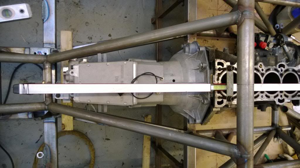
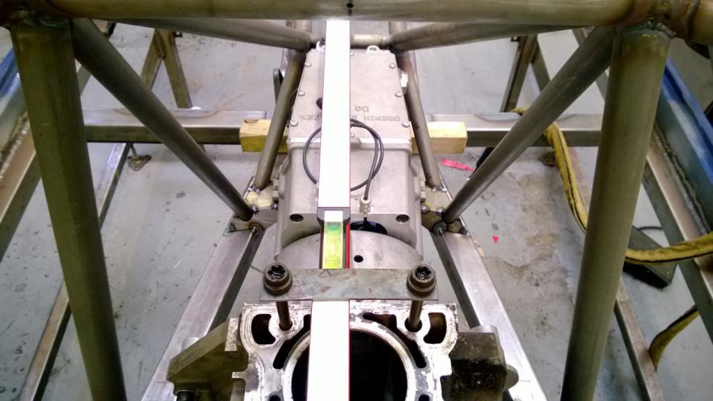
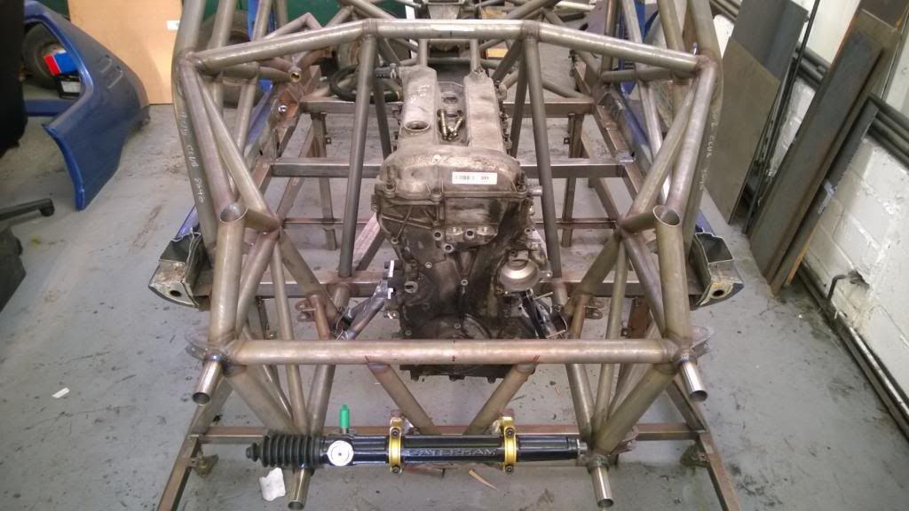
More work this weekend on the engine & gearbox mounts.. yesterday I got the engine and gearbox back in and spent some time getting it all straight and level. I made up some little straps to hold a spirit level on the centreline, then hung plumb lines off either end to get it lined up.
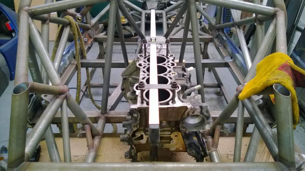
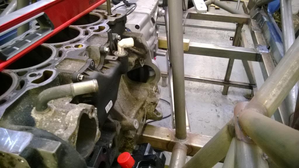
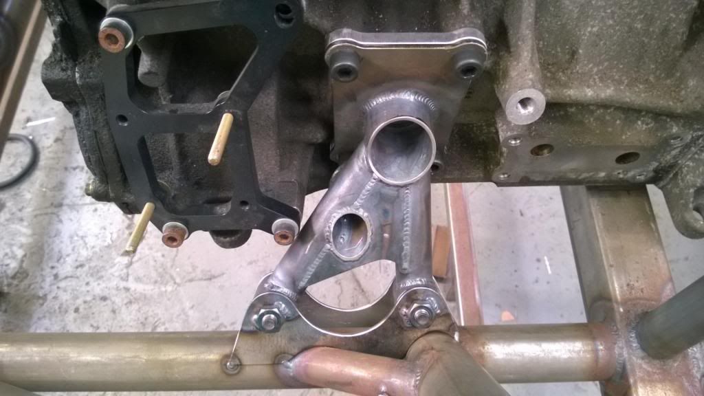
I immediately spotted a problem.. the bolt holes for the starter motor line up really very nicely with this chassis member! There was space, but just not enough to get a bolt in and be able to do it up, so I had to abandon having the engine offset and put it in the centre. It was offset 30mm to the LHS to counter driver weight and make room for the exhaust.
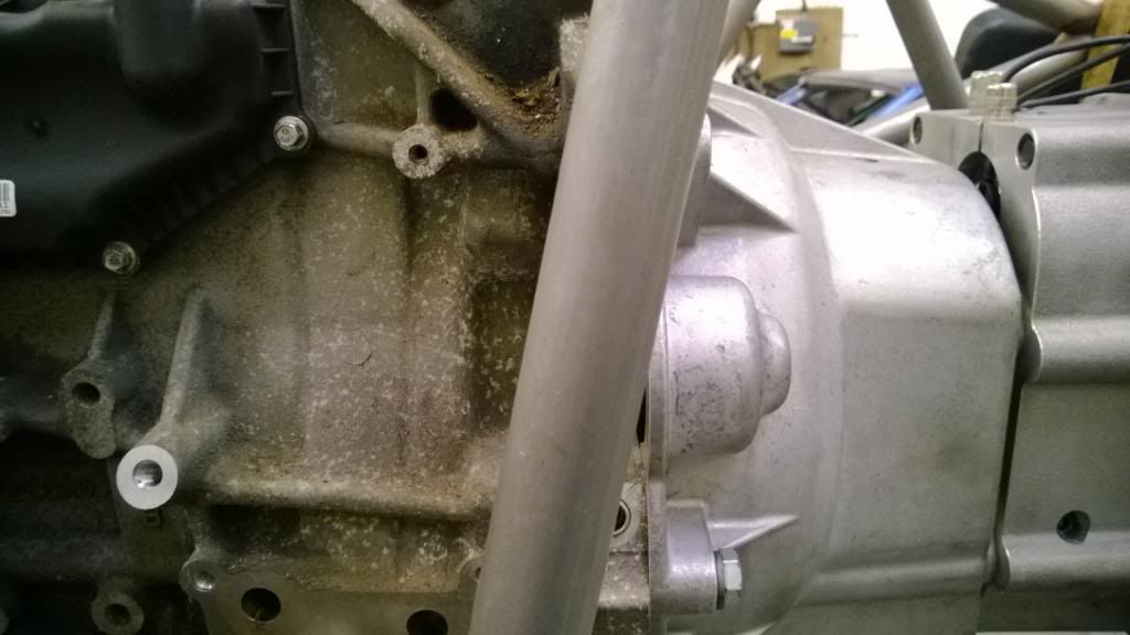
There was space, but trying to get bolts in would be impossible!
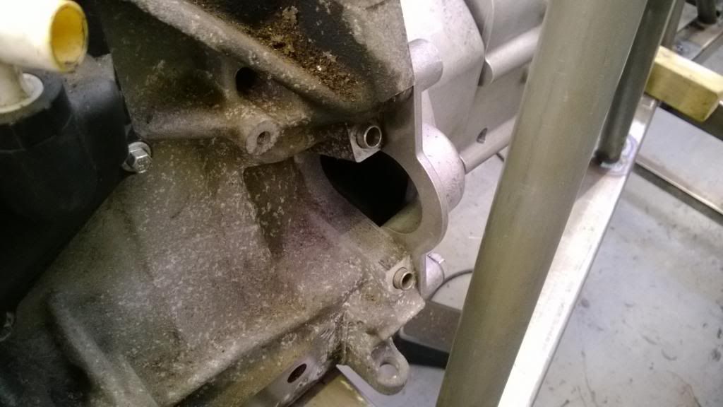
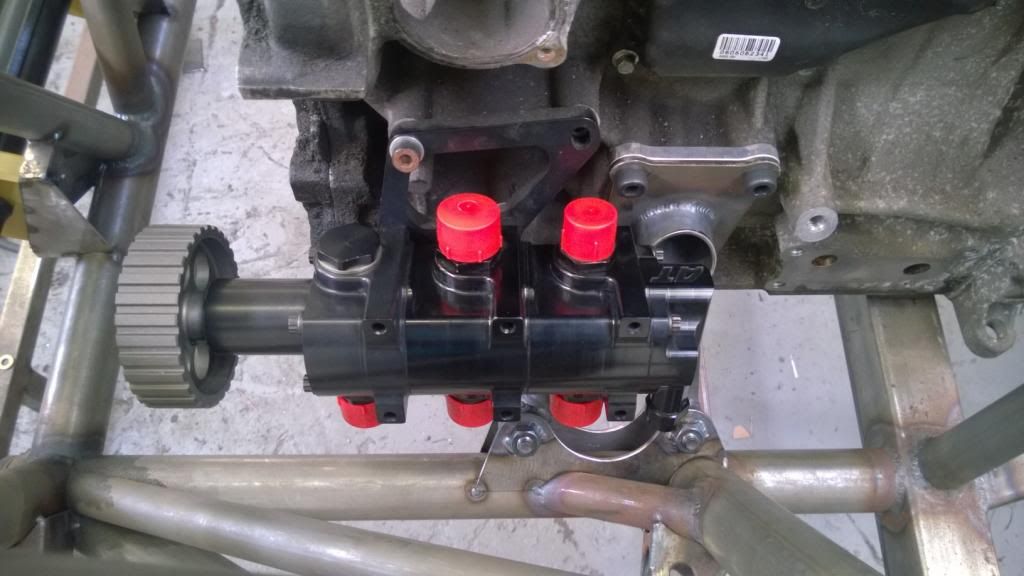
Space was also really tight around the oil pump & engine mount location.
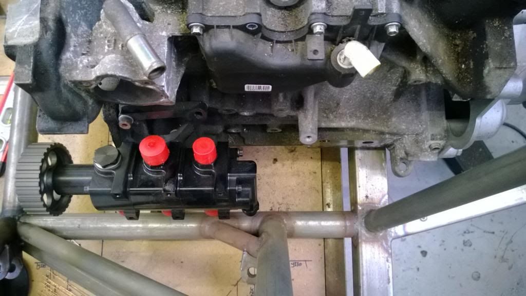
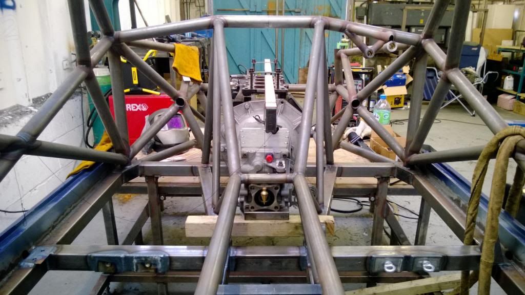
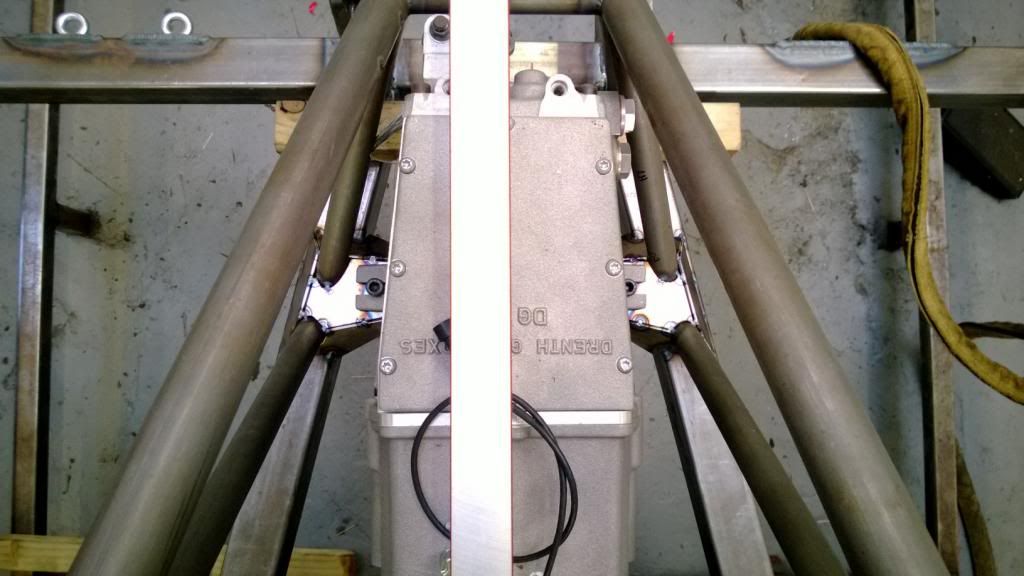
So I went and moved the engine as far back as I possibly could and put the crank line on the centreline of the vehicle, which got me enough room to be able to slip a bolt in and do it up. Thank feck for that, because an engine-out starter swap would have been absurd!
Tight, but enough:
Crank line is now central:
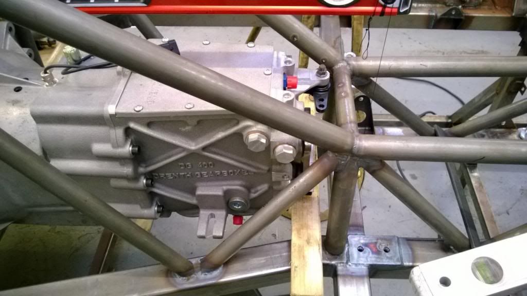
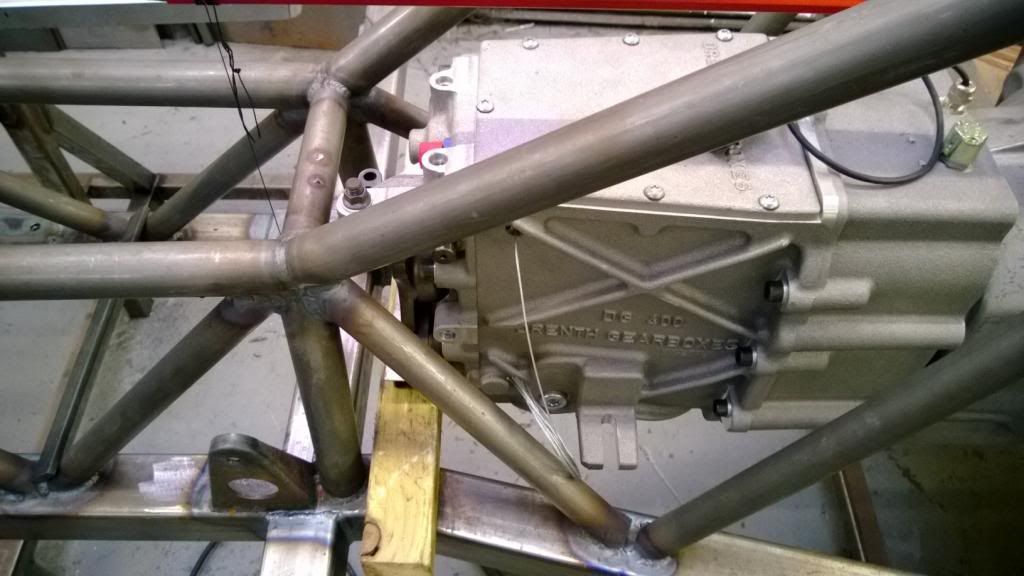
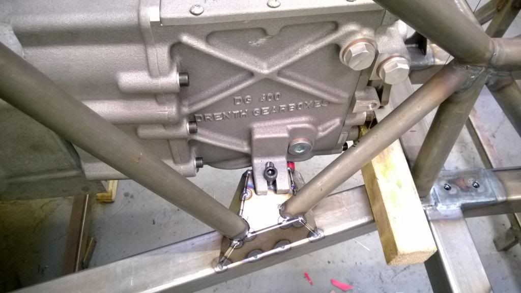
So today (around setting myself on fire (yes I did get pics)) I used some Cardboard Aided Design to make the gearbox mounts.
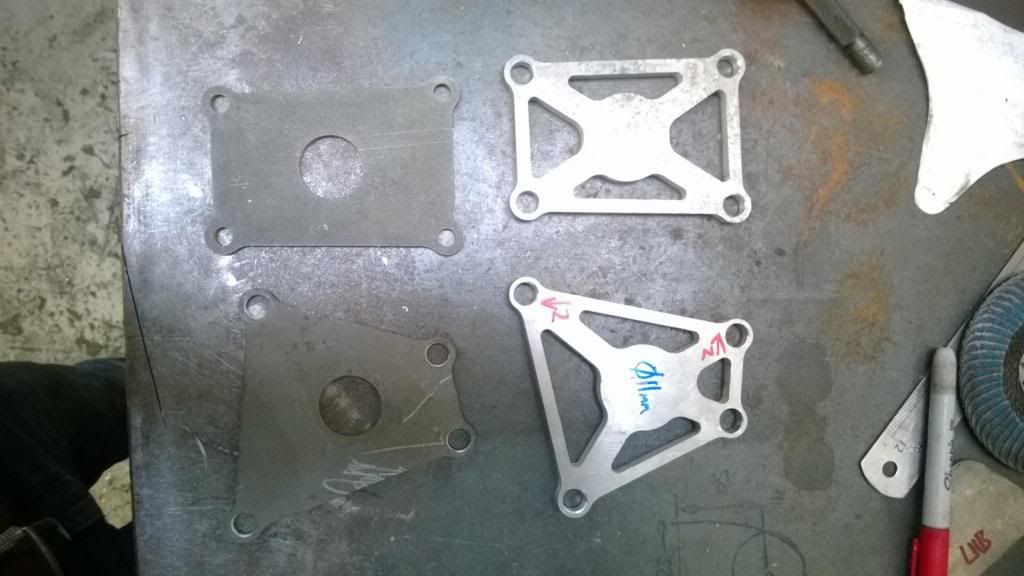
Then I was going to start on the engine mounts, but found that the plates & spacers I'd had water cut weren't quite right.. by the time I had opened the holes up enough to fit I wasn't happy with the amount of material left, so will have to get some new ones made up with revised hole positions.
That's all for now.. I have a few pics of my wheels & brakes now that the centre bores have been machined out and everything fits, but will post tomorrow.
More work this weekend on the engine & gearbox mounts.. yesterday I got the engine and gearbox back in and spent some time getting it all straight and level. I made up some little straps to hold a spirit level on the centreline, then hung plumb lines off either end to get it lined up.
I immediately spotted a problem.. the bolt holes for the starter motor line up really very nicely with this chassis member! There was space, but just not enough to get a bolt in and be able to do it up, so I had to abandon having the engine offset and put it in the centre. It was offset 30mm to the LHS to counter driver weight and make room for the exhaust.
There was space, but trying to get bolts in would be impossible!
Space was also really tight around the oil pump & engine mount location.
So I went and moved the engine as far back as I possibly could and put the crank line on the centreline of the vehicle, which got me enough room to be able to slip a bolt in and do it up. Thank feck for that, because an engine-out starter swap would have been absurd!
Tight, but enough:
Crank line is now central:
So today (around setting myself on fire (yes I did get pics)) I used some Cardboard Aided Design to make the gearbox mounts.
Then I was going to start on the engine mounts, but found that the plates & spacers I'd had water cut weren't quite right.. by the time I had opened the holes up enough to fit I wasn't happy with the amount of material left, so will have to get some new ones made up with revised hole positions.
That's all for now.. I have a few pics of my wheels & brakes now that the centre bores have been machined out and everything fits, but will post tomorrow.
As promised..
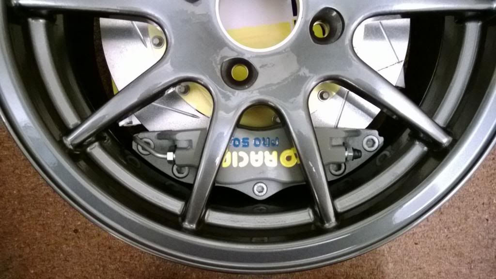
My wheels came back from having the centre bores machined, so I stuck the front brakes in and took some pictures.
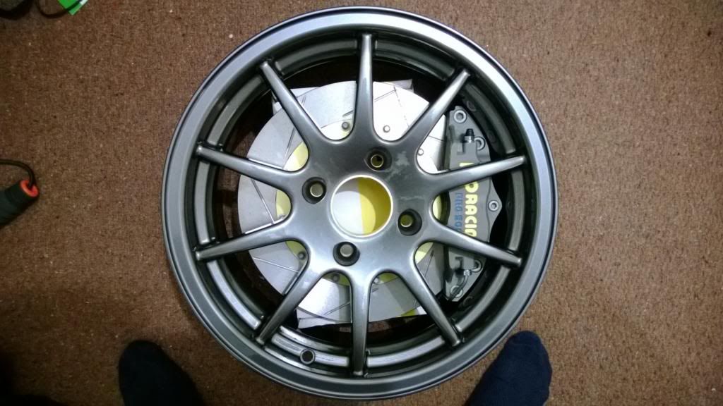
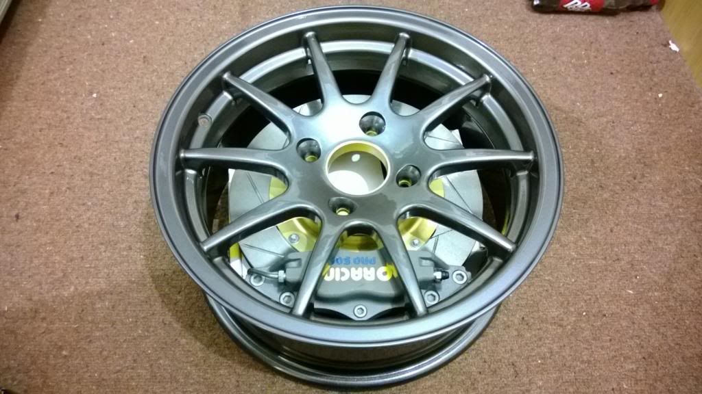
Nothing says motorsport like brakes that barely fit in the wheels.
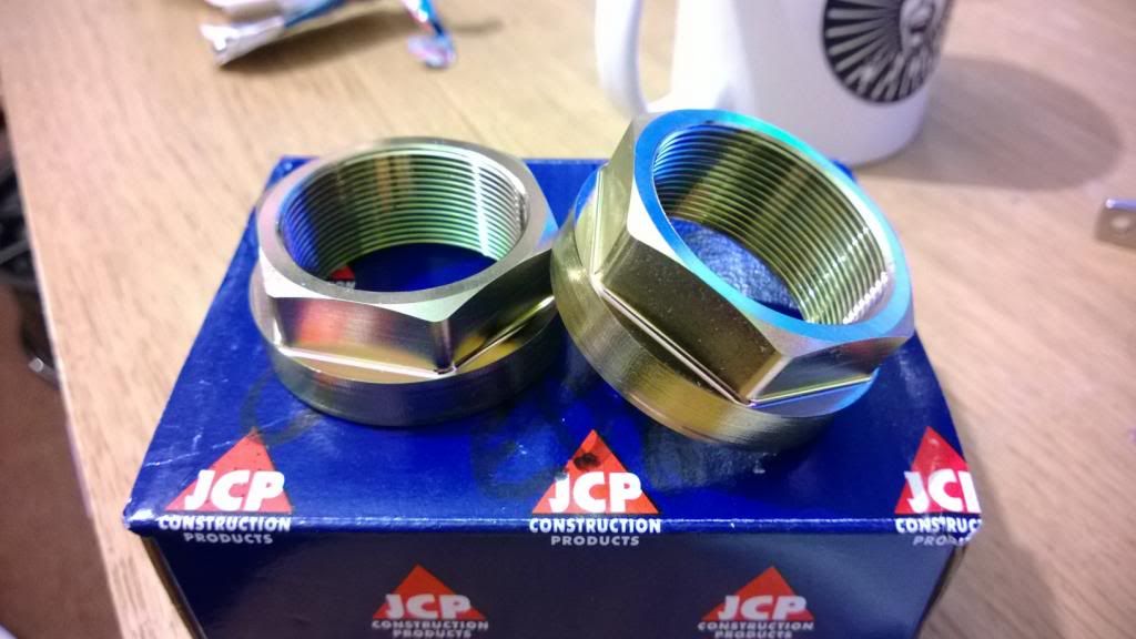
I also got my hub nuts (CNC & coated) back.. for such a seemingly insignificant part I think they look bloody awesome.
My wheels came back from having the centre bores machined, so I stuck the front brakes in and took some pictures.
Nothing says motorsport like brakes that barely fit in the wheels.
I also got my hub nuts (CNC & coated) back.. for such a seemingly insignificant part I think they look bloody awesome.
Haha yeah I was on the FS team at Herts uni in.. err.. 2010? What about you?
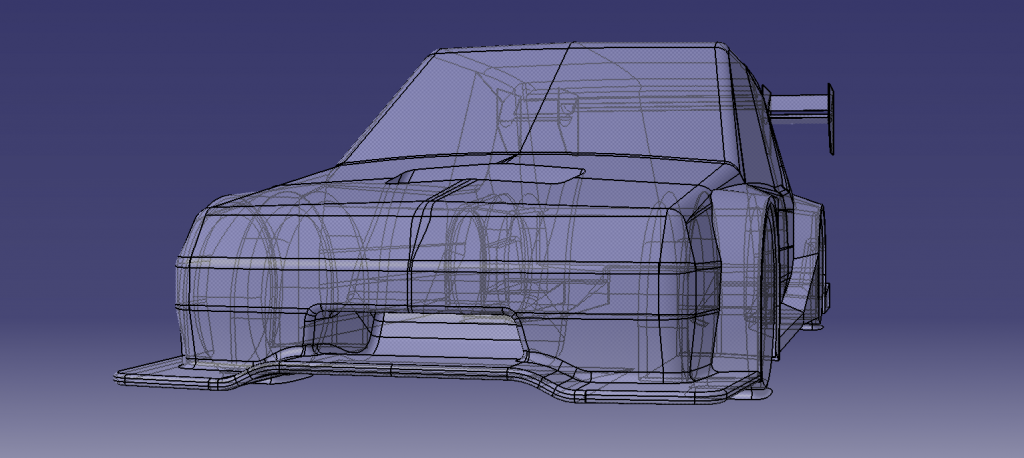
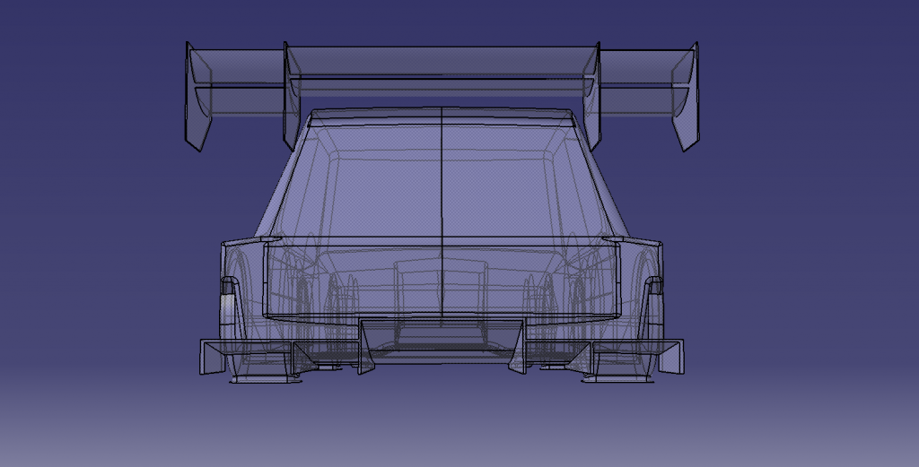
I did have a mate do a laser scan for me of a 205 body, but it was on metallic paint so the surface was pretty soft and difficult to extract. In the end I just used it as a silhouette to adjust what I'd already done to the right sort of shape. I'd love to get hold of a FARO arm or similar so I could digitise a mesh on the body and use that to generate surfaces.. in my limited surfacing experience I'd find that much easier to use!
I did have a mate do a laser scan for me of a 205 body, but it was on metallic paint so the surface was pretty soft and difficult to extract. In the end I just used it as a silhouette to adjust what I'd already done to the right sort of shape. I'd love to get hold of a FARO arm or similar so I could digitise a mesh on the body and use that to generate surfaces.. in my limited surfacing experience I'd find that much easier to use!
CamMoreRon said:
Haha yeah I was on the FS team at Herts uni in.. err.. 2010? What about you?
I did have a mate do a laser scan for me of a 205 body, but it was on metallic paint so the surface was pretty soft and difficult to extract. In the end I just used it as a silhouette to adjust what I'd already done to the right sort of shape. I'd love to get hold of a FARO arm or similar so I could digitise a mesh on the body and use that to generate surfaces.. in my limited surfacing experience I'd find that much easier to use!
I was at Bath, 2004.I did have a mate do a laser scan for me of a 205 body, but it was on metallic paint so the surface was pretty soft and difficult to extract. In the end I just used it as a silhouette to adjust what I'd already done to the right sort of shape. I'd love to get hold of a FARO arm or similar so I could digitise a mesh on the body and use that to generate surfaces.. in my limited surfacing experience I'd find that much easier to use!
Yes, scanning can be difficult on a shiny surface but we have ways around it - usually loads of talc or Flaw Detector Spray.
Looking good as always Cam
Would have suggested maybe getting studs made up for the starter motor issue, but then there's the problem of getting the thing off once the nuts are loose, no winning with some issues.
If you're needing some fibreglass companies to knock up panels or supplies when the time comes, I've got a few contacts i can send over if you need them
Silly question? Have you gone for completely solid gearbox/engine mounts? If so, please slot them longitudinally to allow for powertrain bending and expansion! (otherwise you will be forever snapping lugs off your tranny.......(never a good thing ;-)
(or better, just use hard poly or similar bushes)
(or better, just use hard poly or similar bushes)
Ian - I think having studs would just make the problem worse! At least with bolts I only have to pull the starter away from the block 8mm to clear the dowels.
OlberJ - Yeah it'll be even tighter! I don't have a starter yet, but rest assured I will be getting one very soon to check. I know which one I will use and the part that bolts to the block is very slim, so I'm reasonably confident it'll be ok. Still.. I have to check!
Max Torque - It's solid mounted! The engine mounts will have nylon bushes but how much deflection that will allow I don't know. How much expansion are we talking here? I know exhausts have a habit of expanding some 20mm along the whole length, but that's a few metres of tube and several hundred degrees.. the block & box are quite a bit shorter and cooler so I can't see it being quite as extreme.
Appreciate the comments, guys.
More work today.. sorting the steering rack mounts while I wait for the engine mount plates to be cut.
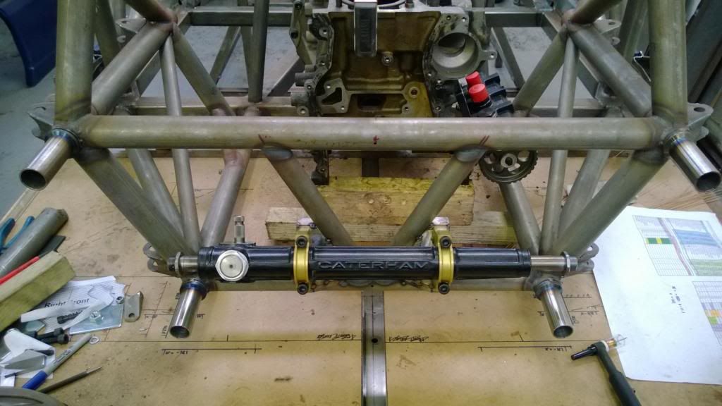
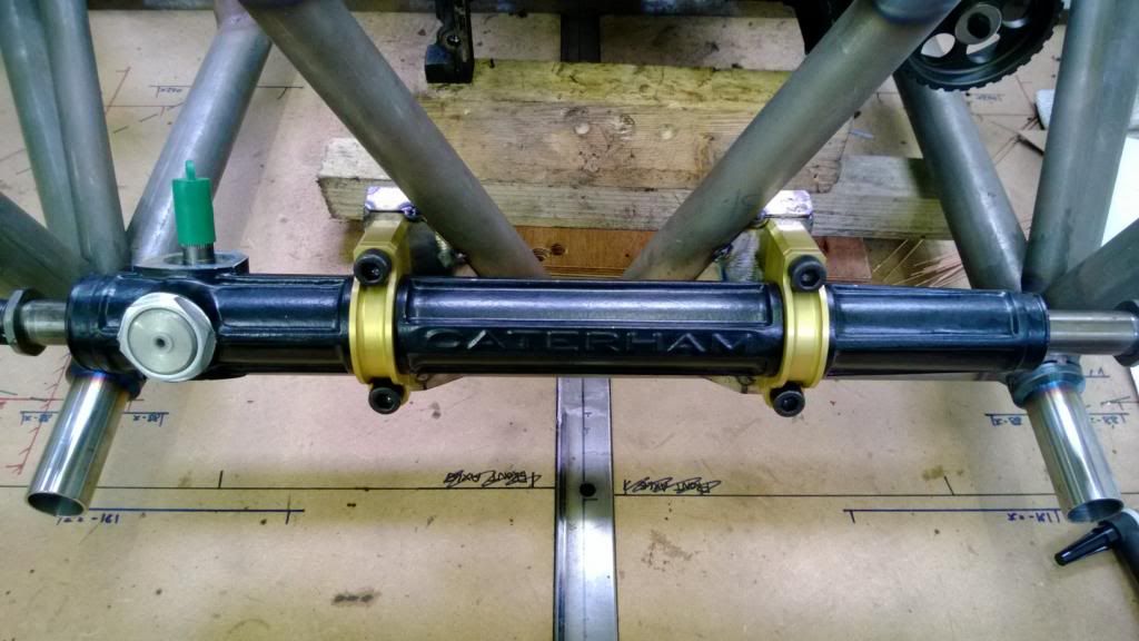
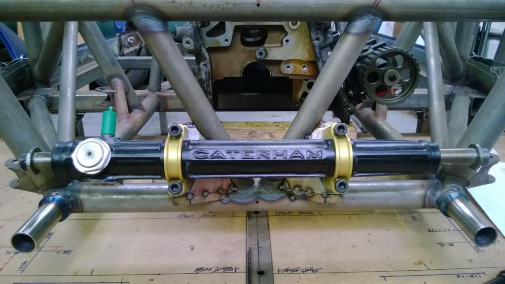
I love these clamps.. they came out so nicely! I borrowed some design ideas from a BMX stem I have - with the top bolt tight you can still twist the rack in the mounts, then the lower bolt has a small gap so that when you tighten that bolt down, everything is solid.
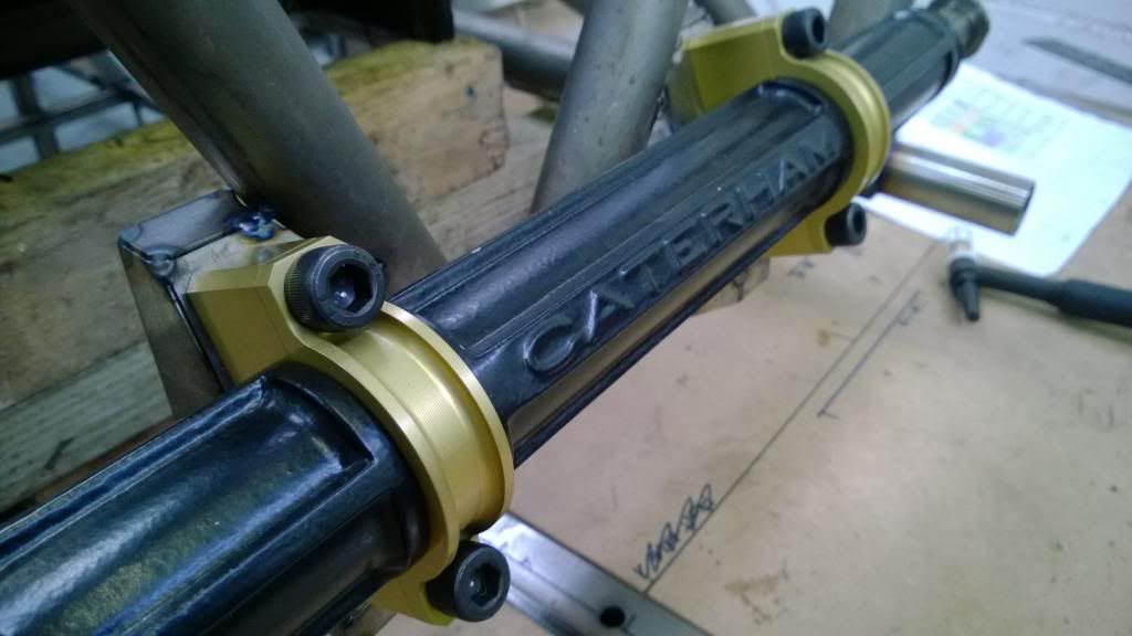
I love these clamps.. they came out so nicely!
I borrowed some design ideas from a BMX stem I have - with the top bolt tight you can still twist the rack in the mounts, then the lower bolt has a small gap so that when you tighten that bolt down, everything is solid. Nothing motivates me more than good weather, and it was so nice this weekend! There's something I love about heading out early when it's cold but the sun is up. Anyway.. engine mounts!
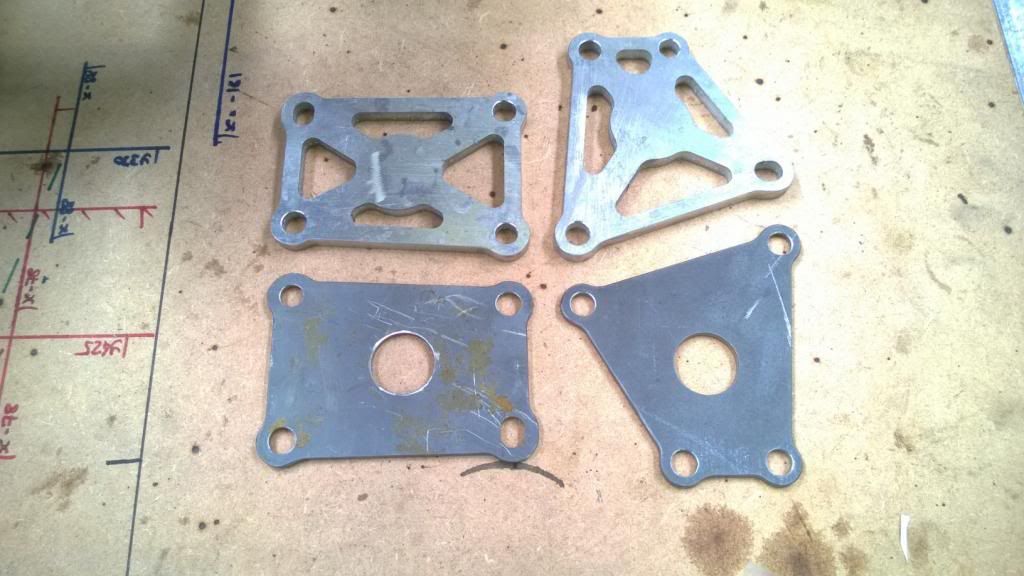
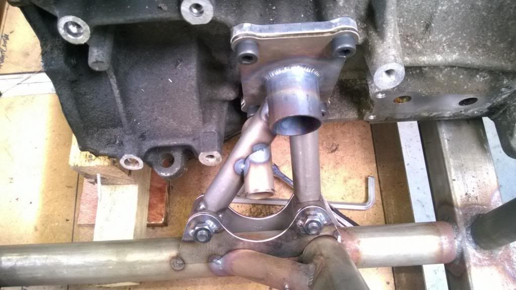
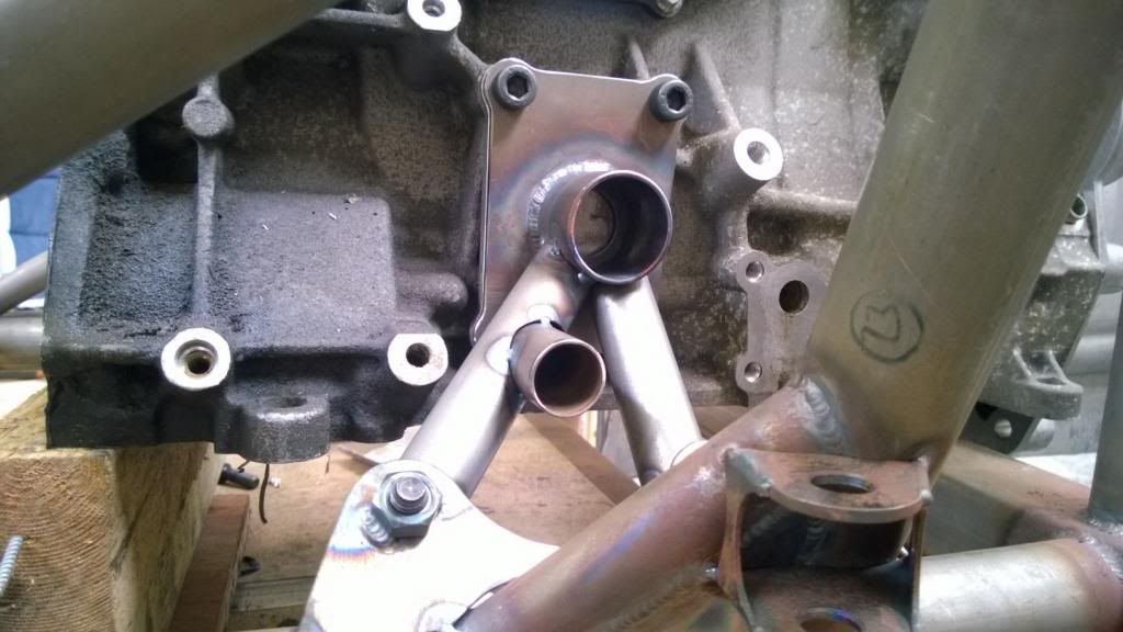
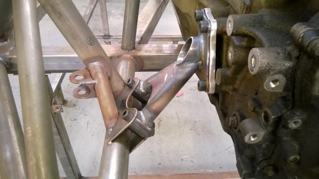
I got my new plates & spacers back from the water jet profiler, and hurrah they now fit both my engine blocks! I turned some aluminium bushes up and pressed them in to some tube, then profiled and tacked everything together.
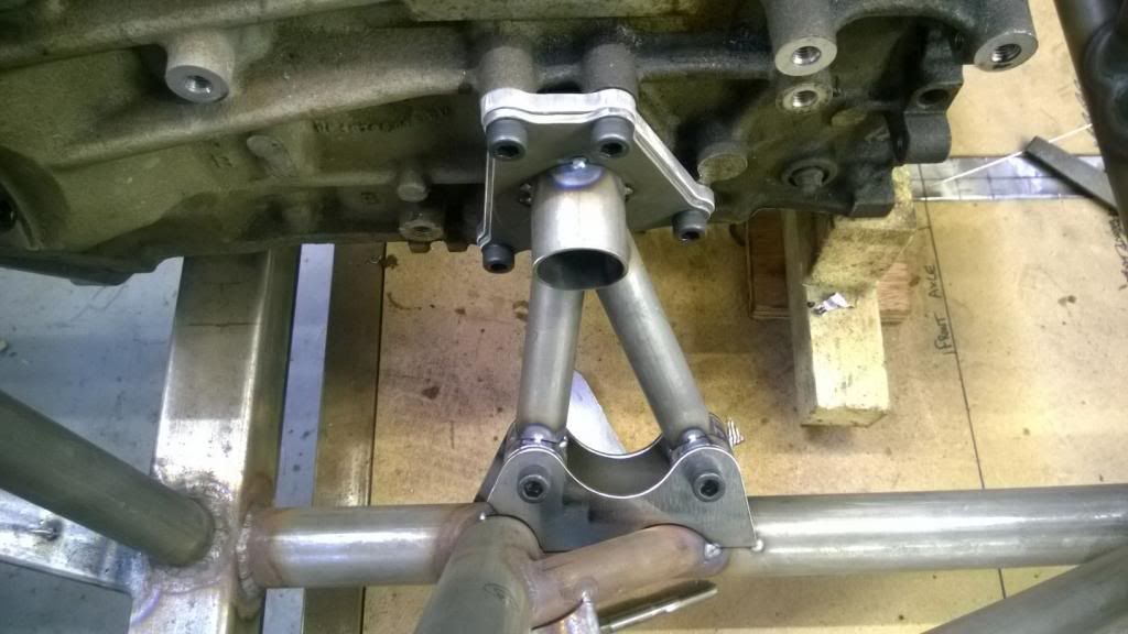
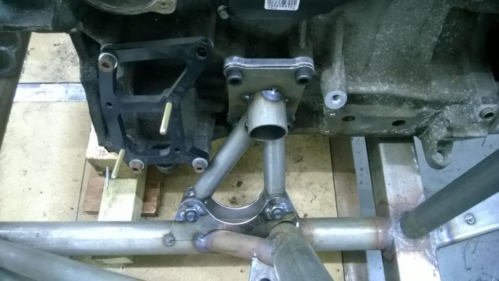
Clearance round the oil pump is very tight!
Slight problem there, being that I couldn't get to one of the screws once the front leg was on! So that had to come off for a re-think, and I fitted a piece of tube to allow me to get a tool in there to do it up.
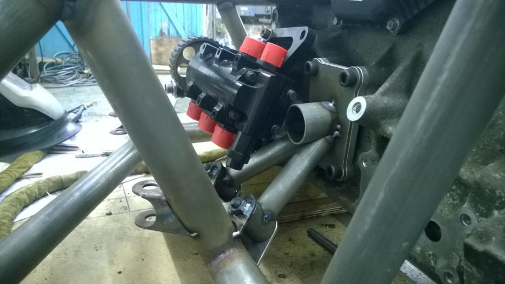
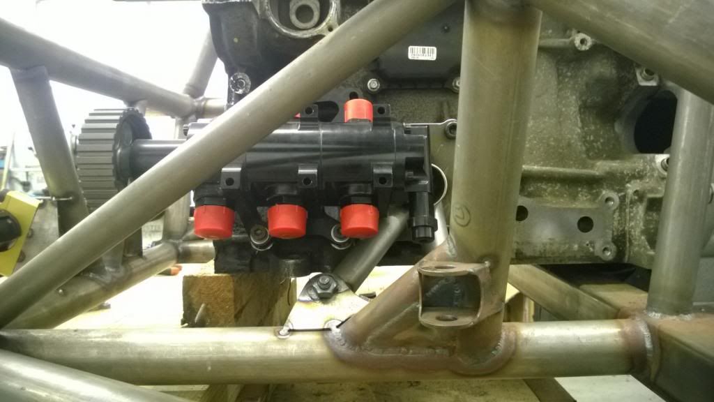
So then it was a case of welding it all up and fitting some simple gussets.
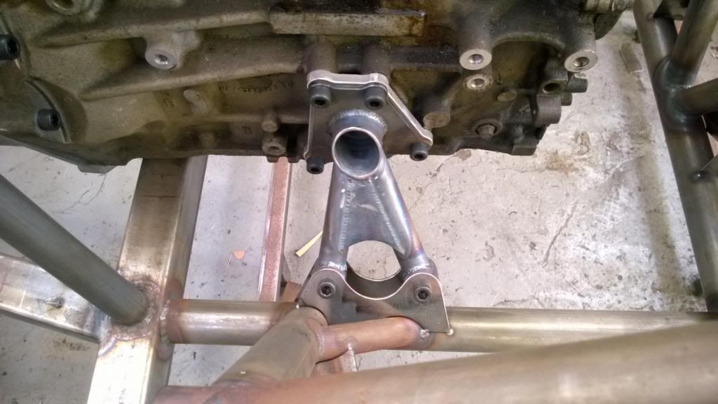
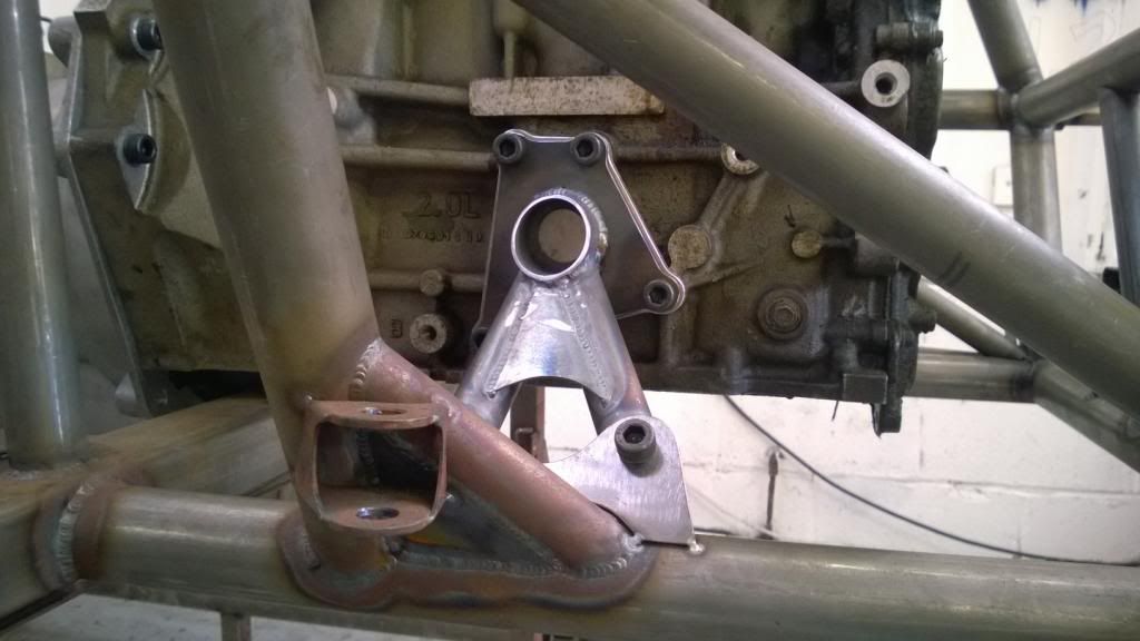
Oil pump still fits, which is nice.
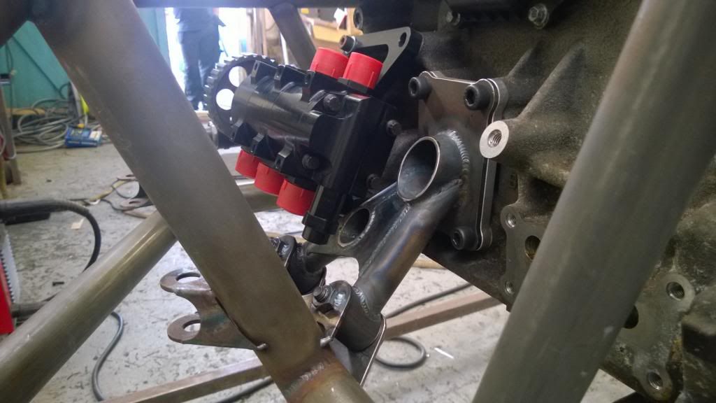
All done! I threw the head and cam cover on, then removed the front half of the jig table so I can do some welding during the week.
I got my new plates & spacers back from the water jet profiler, and hurrah they now fit both my engine blocks! I turned some aluminium bushes up and pressed them in to some tube, then profiled and tacked everything together.
Clearance round the oil pump is very tight!
Slight problem there, being that I couldn't get to one of the screws once the front leg was on! So that had to come off for a re-think, and I fitted a piece of tube to allow me to get a tool in there to do it up.
So then it was a case of welding it all up and fitting some simple gussets.
Oil pump still fits, which is nice.
All done! I threw the head and cam cover on, then removed the front half of the jig table so I can do some welding during the week.
Edited by CamMoreRon on Sunday 9th March 18:43
Gassing Station | Readers' Cars | Top of Page | What's New | My Stuff