What Engine for 500BHP
Discussion


turbonutter said:
Re build.... I am now away at work until December, so no building until next year.....
For now its just some more research & decide which bits I need to order, based on long lead times...
Boost tied to throttle position sounds like a good idea, it should make it much more progressive and the power is just a stab of the right foot away
Most ecu's do allow boost duty linked to TPS anyway.For now its just some more research & decide which bits I need to order, based on long lead times...
Boost tied to throttle position sounds like a good idea, it should make it much more progressive and the power is just a stab of the right foot away
Your Haltech or Syvecs can do this.
As for chargecooler, I think it is better to retain this, and keep the original Stratos look. An IC on the roof would just look wrong.
If the barrel unit proves to lack cooling, just change it for one that will offer better performance.
The last tune up I had them link the boost to TPS, but my wastegate spring is 0.9 bar and full boost just over 1.1, so it didn't make much difference.
I have looked at the wastegate and it has 3 springs to make up the 0.9 bar going off the colour chart on the Tial website, I have a 0.2, 0.3, and 0.4, so the plan is to remove the 0.4 one to give a greater range of control.
The charge cooler will stay, as said above an intercooler on the roof of a stratos wouldn't look right. Plus I tried an intercooler on my last stratos in a different position & its really hard to get any decent airflow to it, yes on the roof would work air flow wise, but it just wouldn't look right.
If when I get some proper logging of the chargecooler performance, i find it isn't up to the job, then I will look at fitting one that will do the job. this one was specced by PWR & they specced the pump and pre-rad as well, so if it dosent work, its down to them to correct their errors.
turbonutter said:
Boost tied to throttle position sounds like a good idea, it should make it much more progressive and the power is just a stab of the right foot away
I can't recommend it enough, makes the car easy to manage, done right (as mine has clearly been) you don't know its there you just instinctively use the throttle to control the power.... It's only looking at the logging data that has shown me how I'm using the throttle.Of cause it helps that the package responds so quickly to the ecu, but like me you have good wastegates and a well thought out package :-)
Btw my car can run 2 bar of boost and I used to run 1.6 bar at 8000rpm via the electronic control and yet I only use a .6 bar spring... .9bar spring is too high, I think I could go even lower but it's so controllable as is I have no plans to change.
Im correct You run trial wastegates like me right? Is your turbo a twin scroll?
Im correct You run trial wastegates like me right? Is your turbo a twin scroll?
turbonutter said:
The last tune up I had them link the boost to TPS, but my wastegate spring is 0.9 bar and full boost just over 1.1, so it didn't make much difference.
I have looked at the wastegate and it has 3 springs to make up the 0.9 bar going off the colour chart on the Tial website, I have a 0.2, 0.3, and 0.4, so the plan is to remove the 0.4 one to give a greater range of control.
The charge cooler will stay, as said above an intercooler on the roof of a stratos wouldn't look right. Plus I tried an intercooler on my last stratos in a different position & its really hard to get any decent airflow to it, yes on the roof would work air flow wise, but it just wouldn't look right.
If when I get some proper logging of the chargecooler performance, i find it isn't up to the job, then I will look at fitting one that will do the job. this one was specced by PWR & they specced the pump and pre-rad as well, so if it dosent work, its down to them to correct their errors.
On the map you posted, your boost is not linked to TPS, other than the fact that the throttle controls how much air enters the engine.I have looked at the wastegate and it has 3 springs to make up the 0.9 bar going off the colour chart on the Tial website, I have a 0.2, 0.3, and 0.4, so the plan is to remove the 0.4 one to give a greater range of control.
The charge cooler will stay, as said above an intercooler on the roof of a stratos wouldn't look right. Plus I tried an intercooler on my last stratos in a different position & its really hard to get any decent airflow to it, yes on the roof would work air flow wise, but it just wouldn't look right.
If when I get some proper logging of the chargecooler performance, i find it isn't up to the job, then I will look at fitting one that will do the job. this one was specced by PWR & they specced the pump and pre-rad as well, so if it dosent work, its down to them to correct their errors.
From what I can tell, your firmware version doesnt even offer it. You would need to upgrade to newer firmware to gain that option ( it's free to do so )

Unfortunately no.
There is no TPS load axis there, so once again this "mapper" was maybe watching Coronation Street instead of the actual Haltech software when he was "tuning"
Look at some of the other base maps and you can see the TPS Target correction or similar tables within the boost control setup. MY01-05 Subaru is one example
As we know I am no mapping expert, but learning slowly......
This was the same map page before the last "tune up" when they said that they had tied the boost to the throttle opening as I was complaining about the harsh change in power/lack of control when trying to feather the throttle and control wheel spin....
OK The picture upload is not working again, but it is the same as above, only the valuse in the zero column are the same as the 100 column not zero's
If it didnt do that, could it have caused the det?
I see what you mean about the Subaru map and boost to throttle calibration...
Edited by turbonutter on Wednesday 18th September 21:48
TBH I'm not even sure what that would do.
It seems to be boost duty against rpm and fuel load....weirdest possible axis you could ever choose.
I'd almost go as far as to say I think you're running on w/g pressure only, with virtually no ecu control over boost at all. Certainly no sensible amount of control.
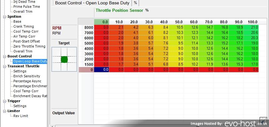
Looking at the software again, this is what should have been done to allow boost duty to vary with TPS and RPM. This is just open loop, so not directly linked to any target pressure as in a closed loop setup.
Nothing wrong with it this way of course.
Now if Rick happens to read this. There is a big clue in the table setup in order to make it linked to TPS. It's that table axis called "Throttle Position Sensor"
I know Haltech made that very difficult to understand....
The more you look, the more it defies belief
It seems to be boost duty against rpm and fuel load....weirdest possible axis you could ever choose.
I'd almost go as far as to say I think you're running on w/g pressure only, with virtually no ecu control over boost at all. Certainly no sensible amount of control.
Looking at the software again, this is what should have been done to allow boost duty to vary with TPS and RPM. This is just open loop, so not directly linked to any target pressure as in a closed loop setup.
Nothing wrong with it this way of course.
Now if Rick happens to read this. There is a big clue in the table setup in order to make it linked to TPS. It's that table axis called "Throttle Position Sensor"
I know Haltech made that very difficult to understand....
The more you look, the more it defies belief
It is sort of TPS based though isn't it, because the fuel load axis is TPS based?
I suspect though, that considering most w/g control solenoids have an effective operation only between about 10-90%, that mapping is really doing very little. With the current w/g spring, as you say, your min boost line is way too close to the boost target, leaving little room for pressure modulation. As such, that "map" only changes by 4% across the engine speed range, which i'd hazard a guess is below the actual control resolution of the valve/ wg system!
With remote wastegates that have two pressure tappings (above & below the diaphram) you can run dual control solenoids operating in antiphase to broaden the pressure control range, and make the car very very drivable on the throttle. In the ideal world, you also control boost to a target pre throttle pressure, giving improved throttle response and excellent transient performance.
Finally, generally, one should set the open loop duty tables to "full boost" (100% venting) in regions below the boost energy threshold (say below ~3000rpm and 40% throttle etc). This ensures the wastegate stays fully shut during the spool up.
Edited by anonymous-user on Wednesday 18th September 22:55
Max_Torque said:
It is sort of TPS based though isn't it, because the fuel load axis is TPS based?
I suspect though, that considering most w/g control solenoids have an effective operation only between about 10-90%, that mapping is really doing very little. With the current w/g spring, as you say, your min boost line is way too close to the boost target, leaving little room for pressure modulation. As such, that "map" only changes by 4% across the engine speed range, which i'd hazard a guess is below the actual control resolution of the valve/ wg system!
With remote wastegates that have two pressure tappings (above & below the diaphram) you can run dual control solenoids operating in antiphase to broaden the pressure control range, and make the car very very drivable on the throttle. In the ideal world, you also control boost to a target pre throttle pressure, giving improved throttle response and excellent transient performance.
Finally, generally, one should set the open loop duty tables to "full boost" (100% venting) in regions below the boost energy threshold (say below ~3000rpm and 40% throttle etc). This ensures the wastegate stays fully shut during the spool up.
A single 4 port solenoid basically does that same job.I suspect though, that considering most w/g control solenoids have an effective operation only between about 10-90%, that mapping is really doing very little. With the current w/g spring, as you say, your min boost line is way too close to the boost target, leaving little room for pressure modulation. As such, that "map" only changes by 4% across the engine speed range, which i'd hazard a guess is below the actual control resolution of the valve/ wg system!
With remote wastegates that have two pressure tappings (above & below the diaphram) you can run dual control solenoids operating in antiphase to broaden the pressure control range, and make the car very very drivable on the throttle. In the ideal world, you also control boost to a target pre throttle pressure, giving improved throttle response and excellent transient performance.
Finally, generally, one should set the open loop duty tables to "full boost" (100% venting) in regions below the boost energy threshold (say below ~3000rpm and 40% throttle etc). This ensures the wastegate stays fully shut during the spool up.
Edited by Max_Torque on Wednesday 18th September 22:55
Although I see Turbosmart and others suggest connecting a regular 3 port like that. With one port to top side and the other to the bottom. Although they are aiming it for people running a high boost level as opposed to a very low one
The boost control is working on my setup, as I have a control Knob to turn it down - & I can control it from 1.1 or 1.2 down to the spring pressure of 0.9. I will remove one of the 3 springs so that I can control it down to 0.5bar when I rebuild it.
I an connectrd like this:

The supply pressure comes from just after the boost pipe before the charge cooler.
I an connectrd like this:
The supply pressure comes from just after the boost pipe before the charge cooler.
Whilst the average boost pressure may be under control with your current setup, that is really just due to the inherent mechanical negative feedback loop in the system. Your EMS controlled bleed valve is really just acting as a dumb overall "shift" to move the boost line up and down. With a properly calibrated system, ideally using a base open loop feedforward table plus a high bandwidth PI control strategy on top, you can dynamically control boost (i.e. during gear shifts, engine speed transients, during spool up etc, and account for variations in ambient pressure and turbo efficiency). As such, i would expect a properly matched mechanical / pneumatic layout to use something approaching 60% of the BCV's range (not 4% as in your case.....) Targeting approx 75% duty to achieve the average static boost target gives you some control headroom for maintaining that boost during higher ambient temperatures (when the IC efficiency is lower) and at altitude (lower pre compressor pressure). Typical BCVs are effectively shut below ~10%dc and open above ~90%dc.
just as a side note, I would try to reduce the amount of rubber pipe between the wastegate and were-ever you have taken the reading from... on my car I took the reading from the turbo outlet by drilling and tapping into the housing just before the hose... I thin used bent brake line right to the valve and to the wastegates.
This can help the wastegate repond faster to the ecu commands and give better driving response and control
this thread made me buy a book on ecu mapping that I have read cover to cover this week (while on plane etc) so I now have a lot more understanding about my own map
Also Im going to strip my engine and inspect it over the winter (along with a few tweeks of cause)... my thoughts are that doing this will be a huge amount cheaper and easier than fixing something that went wrong that i didn't know about lol
andygtt said:
just as a side note, I would try to reduce the amount of rubber pipe between the wastegate and were-ever you have taken the reading from... on my car I took the reading from the turbo outlet by drilling and tapping into the housing just before the hose... I thin used bent brake line right to the valve and to the wastegates.
This can help the wastegate repond faster to the ecu commands and give better driving response and control
this thread made me buy a book on ecu mapping that I have read cover to cover this week (while on plane etc) so I now have a lot more understanding about my own map
Also Im going to strip my engine and inspect it over the winter (along with a few tweeks of cause)... my thoughts are that doing this will be a huge amount cheaper and easier than fixing something that went wrong that i didn't know about lol
I would agree on short tubing, I would not agree on such small diameter, especially if lots of air is being vented to achieve a high boost setting.This can help the wastegate repond faster to the ecu commands and give better driving response and control
this thread made me buy a book on ecu mapping that I have read cover to cover this week (while on plane etc) so I now have a lot more understanding about my own map
Also Im going to strip my engine and inspect it over the winter (along with a few tweeks of cause)... my thoughts are that doing this will be a huge amount cheaper and easier than fixing something that went wrong that i didn't know about lol
Brake pipe is tiny, and air would travel through it very slowly
stevieturbo said:
I would agree on short tubing, I would not agree on such small diameter, especially if lots of air is being vented to achieve a high boost setting.
Brake pipe is tiny, and air would travel through it very slowly
The tubing is pretty short, see below were the take off is - To move teh solenoid any closer to the waste gate would put it in a hot area, which i dont think is a good idea....Brake pipe is tiny, and air would travel through it very slowly

Gassing Station | Engines & Drivetrain | Top of Page | What's New | My Stuff