Instructions to change fuel maps on 14CUX Griffith, Chimaera
Discussion


CGCobra
Welcome & thanks for your kind words, yes you are in the right place.
In addition the advantage of running map2 is you can set your idle AFR to 13.5 to improve idle and slow speed running by setting the CO Trim screw on the AFM to 1.4 volts as seen in RoverGauge. To see the CO Trim voltage change in real time you need to fire up and then turn off the ignition long enough to stop the engine and then quickly back on again.
Good Luck and let us know how you get on.
Steve Sprint
Welcome & thanks for your kind words, yes you are in the right place.
CGCobra said:
I don't believe for one minute the engine is actually producing those readings oscillating between 7.x and 20.x would give very poor running if at all, in-fact the engine runs reasonably well.
I agree, if your AFR is really fluctuating between 8 and 20 your engine would be very hesitant, shunting and wouldn’t accelerate smoothly especially when its 20, I guess you’ve tried re-calibrating your LC-1 sensor and also I’m sure you are aware the probe mounting angle is critical. CGCobra said:
I have other issues with the Innovate software, sometimes it will detect the sensor other times it won't, may be my laptop, need to try on another. Eventually I'll be taking an analogue output into the MS and will see if that works any better than the serial into my laptop.
MPO and I run Innovate LC-2 without issues and merge the AFR logs with the RoverGauge logs to insert the AFR for the active cells in the fuel table. My LC-2 is 100% reliable, outputs records every 0.1 sec and you’re welcome to use my LC-2 AFR logger & merger.CGCobra said:
I've used "TVR Griffith 400 Precat & TVR Chimmaera 400 CAT combined in Land Rovers final revision R3652" from Steve Sprints site. I'm assuming that 'precat' means the green map is programmed?
Thanks DaveCGCobra said:
My understanding is this gives the latest program as well as a TVR map?
CorrectCGCobra said:
Only slight issue I have with this is the idle control seems different and not as good on my car as my previous chip, particularly when cold.
Sorry to hear you are experiencing idle issues with map 2 of “TVR Griffith 400 Precat & TVR Chimmaera 400 CAT combined in Land Rovers final revision R3652”, I’m surprised ‘it sometimes stalls when you come to a stop’, which interestingly is a similar symptom to a faulty road speed sensor. I’ve heard of high idle issues with R3652 while slowing down that I've since learnt how to control and fixed on my 4.3. Do you get a road speed sensor sensor fault code 68???CGCobra said:
Is there a better "starting point" for my setup?
Yes, it might be worth taking a step back to help identify the where the issue lies, therefore please can you try “TVR Griffith 400 Precat & TVR Chimmaera 400 CAT combined in later TVR R2967” and let me know if its any better. In addition the advantage of running map2 is you can set your idle AFR to 13.5 to improve idle and slow speed running by setting the CO Trim screw on the AFM to 1.4 volts as seen in RoverGauge. To see the CO Trim voltage change in real time you need to fire up and then turn off the ignition long enough to stop the engine and then quickly back on again.
CGCobra said:
My speed sensor gives an analogue output proportional to roadspeed (although about half the rate of a Rover unit apparently) not the binary (moving / not-moving) signal a TVR seems to have. Don't know if this makes the difference)
No, the exact road speed calibration is unimportant and is only used to set the target idle once stationary and to limit the max road speed which is by-passed in the program code of TVR R2967 & my R3652.Good Luck and let us know how you get on.
Steve Sprint
I’ve recently been informed that R2967 was also used on early MGR V8s which means back in 1993 (sound a familiar date??), therefore was R2967 originally for the MGR V8 and Rover by-passed the road speed limiter in the code for the MGR V8, makes more sense.
TVR wouldn’t have bothered removing the road speed limiter in the code because TVR went to the expense of installing a signal generator in the speedo calibration box to limit the road speed signal fed into into the 14CUX to 30 mph because the GKN and BTR crown wheels have too many teeth/pulses for the 14CUX.
Does anyone have a copy of R2967 from a MGR V8 I can compare with TVR's R2967 ???? Please .
.
TVR wouldn’t have bothered removing the road speed limiter in the code because TVR went to the expense of installing a signal generator in the speedo calibration box to limit the road speed signal fed into into the 14CUX to 30 mph because the GKN and BTR crown wheels have too many teeth/pulses for the 14CUX.
Does anyone have a copy of R2967 from a MGR V8 I can compare with TVR's R2967 ???? Please
.CGCobra
You can compare the main tuning parameters in my tune settings spreadsheet @ http://www.stevesprint.com/remap-14cux/LR-TVR-sett... . It's now also possible to compare the program source code thanks to Dan and Colin’s huge effort reverse engineering 10 different binary files and cleverly merging them into one rebuild project and commenting all 20,000 lines of assembler code & data, staggering, absolutely staggering. Dan’s source code is available at https://github.com/colinbourassa/14cux-firmware , be warned its not easy but Dan’s running commentary makes it less impossible to follow.
Sounds like you need to try your LC-1 on another computer to prove a point and agreed it should be alright after being in the box a few years.
Here’s a link to my AFR logger including a sample log file www.stevesprint.com/remap-14cux/AFR_Logger.zip
BUT !!! I’m not sure it will work 'out of the box' with your LC-1, unscrambling the LC2s output was stupidly complicated involving bit shifting the data and I still don’t know how I managed it. I don’t know if the LC1's output is in the same format but if not I’m prepared to have ago for you. We run both loggers in tandem and my AFR logger time stamps every AFR record in real time with the system time (like RG) so the AFR records can be matched by time afterwards with MPO's or my merger.
Here's a screen shot of my AFR logger and Rovergauge running in Tandem.
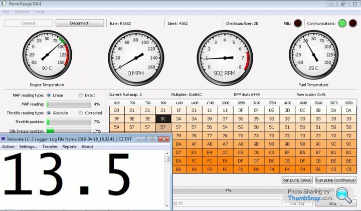
The only sad news is the 14CUX's serial port is starved out above 5,200rpm and stops logging, but at least you know above 5,200rpm your between the last two columns of the fuel table.
I should also warn you self remapping is an addictive time consuming slippery slope analysing and tweaking data, but personally I enjoy being busy and self-sufficient plus I'm too tight to pay someone else to do it for me. However, if I've put you off Joolz at Kits and Classic can fully remap your existing map/chip in an afternoon on his own rolling road for a reasonable price and I've heard lots of positive reports.
Here you can see I've mounted my wideband just above the centre line of the pipe after the Y to catch both banks and it works a treat.

The ECU does learn and store a stepper motor offset along with the fault codes and lamda trims, I've always struggled to understand how and when the stepper motor saved value is updated. Maybe we should ask Colin to add a new window to RoverGauge to display the battery saved data, it would make understand the steppers motor behaviour and issues a lot easier.
Dave has modified the 14CUX code in the past to recalibrate the RoverGauge Speedo, however your idea of adding a calibration multipler setting to RoverGauge is a much better idea because you can still run the OEM tune files.
Please don’t toy with the idea of relying on the 14CUX's speedo for your dashboard speedo, trust me its not reliable enough, use your road speed sensor and a programmable speedo.
Running Lambas is a disadvantage because you loose the flexibility to tweak the AFR to eliminate shunting, the lambda probes are used to help cycle the AFR around 14.7 to make the cats more efficient, I’ll let Mark explain in more detail.
Good luck with the further testing and please remember a road speed sensor fault will cause stalling while slowing down.
Good Night
Steve
You can compare the main tuning parameters in my tune settings spreadsheet @ http://www.stevesprint.com/remap-14cux/LR-TVR-sett... . It's now also possible to compare the program source code thanks to Dan and Colin’s huge effort reverse engineering 10 different binary files and cleverly merging them into one rebuild project and commenting all 20,000 lines of assembler code & data, staggering, absolutely staggering. Dan’s source code is available at https://github.com/colinbourassa/14cux-firmware , be warned its not easy but Dan’s running commentary makes it less impossible to follow.
Sounds like you need to try your LC-1 on another computer to prove a point and agreed it should be alright after being in the box a few years.
Here’s a link to my AFR logger including a sample log file www.stevesprint.com/remap-14cux/AFR_Logger.zip
BUT !!! I’m not sure it will work 'out of the box' with your LC-1, unscrambling the LC2s output was stupidly complicated involving bit shifting the data and I still don’t know how I managed it. I don’t know if the LC1's output is in the same format but if not I’m prepared to have ago for you. We run both loggers in tandem and my AFR logger time stamps every AFR record in real time with the system time (like RG) so the AFR records can be matched by time afterwards with MPO's or my merger.
Here's a screen shot of my AFR logger and Rovergauge running in Tandem.
The only sad news is the 14CUX's serial port is starved out above 5,200rpm and stops logging, but at least you know above 5,200rpm your between the last two columns of the fuel table.
I should also warn you self remapping is an addictive time consuming slippery slope analysing and tweaking data, but personally I enjoy being busy and self-sufficient plus I'm too tight to pay someone else to do it for me. However, if I've put you off Joolz at Kits and Classic can fully remap your existing map/chip in an afternoon on his own rolling road for a reasonable price and I've heard lots of positive reports.
Here you can see I've mounted my wideband just above the centre line of the pipe after the Y to catch both banks and it works a treat.
The ECU does learn and store a stepper motor offset along with the fault codes and lamda trims, I've always struggled to understand how and when the stepper motor saved value is updated. Maybe we should ask Colin to add a new window to RoverGauge to display the battery saved data, it would make understand the steppers motor behaviour and issues a lot easier.
Dave has modified the 14CUX code in the past to recalibrate the RoverGauge Speedo, however your idea of adding a calibration multipler setting to RoverGauge is a much better idea because you can still run the OEM tune files.
Please don’t toy with the idea of relying on the 14CUX's speedo for your dashboard speedo, trust me its not reliable enough, use your road speed sensor and a programmable speedo.
Running Lambas is a disadvantage because you loose the flexibility to tweak the AFR to eliminate shunting, the lambda probes are used to help cycle the AFR around 14.7 to make the cats more efficient, I’ll let Mark explain in more detail.
Good luck with the further testing and please remember a road speed sensor fault will cause stalling while slowing down.
Good Night
Steve
Colin
Further to my post above please can you consider displaying in RoverGauge the following battery saved data, especially the stprMtrSavedValue as it would help us understand stepper motor issues.
stprMtrSavedValue
throttlePotMinimum
hiFuelTemperature
I assume there’s no point displaying longLambdaTrimL/R as the trims are already on the main screen. I don’t mind if you squeeze them in on the main window or add a new window, what ever is easier.
Also, please can you consider CGCobra suggestion to add a calibration multiplier for the RoverGauge speedo and logs as it would save modifying and running bespoke bins.
No rush winter is on its way.
Much appreciated
Steve
CGCobra
I'm pleased your LC1 works and with my logger, sorry here's a link to my merger program, www.remap-14cux.info/MergeAFR&RGLogs.exe
Yes I do also get the Warm up & O2 level in 1/10Per messages going off the screen and never fixed them as it still logs and I usually closed the laptop while logging, I’ll try and fix them this winter.
I should explain that on a power run past 5,200 rpm the log merger inserts blank RoverGauge records above 5,200 rpm with the correct time and AFR which I then manually enter the active row/columns plus delete some records at the end of the file. I then import into excel and create a pivot table like the one below, I'm sure you realise in the log column 0 is the first column.

I wrote the merger for my personal use so its very basic & not robust as commercial software but does the job, maybe I should add it to the logger. I welcome any suggestions like creating fuel table row/column rounded columns for excel or removing the records at the end of the merged file without AFR reading.
Also one final thing, while logging try moving the throttle gradually and smoothly to reduce sudden throttle enrichment.
This wiring diagram should answer some of your other questions www.remap-14cux.info/14CUX Wire Diagram.pdf, connect the neutral/auto gear wire as per this diagram, pin 34.
You're very welcome & enjoy
Steve
I'm pleased your LC1 works and with my logger, sorry here's a link to my merger program, www.remap-14cux.info/MergeAFR&RGLogs.exe
Yes I do also get the Warm up & O2 level in 1/10Per messages going off the screen and never fixed them as it still logs and I usually closed the laptop while logging, I’ll try and fix them this winter.
I should explain that on a power run past 5,200 rpm the log merger inserts blank RoverGauge records above 5,200 rpm with the correct time and AFR which I then manually enter the active row/columns plus delete some records at the end of the file. I then import into excel and create a pivot table like the one below, I'm sure you realise in the log column 0 is the first column.
I wrote the merger for my personal use so its very basic & not robust as commercial software but does the job, maybe I should add it to the logger. I welcome any suggestions like creating fuel table row/column rounded columns for excel or removing the records at the end of the merged file without AFR reading.
Also one final thing, while logging try moving the throttle gradually and smoothly to reduce sudden throttle enrichment.
This wiring diagram should answer some of your other questions www.remap-14cux.info/14CUX Wire Diagram.pdf, connect the neutral/auto gear wire as per this diagram, pin 34.
You're very welcome & enjoy
Steve
Edited by stevesprint on Monday 26th September 19:52
CGCobra said:
I read more of the detail on your site yesterday evening, found the section where you indicated you'd 'massaged' the data manually so I put together a macro on Excel to remove the non-numeric data (O2... & Warm up.... records), it then allocates the AFR data closest in time to the RG data and removes all other AFR data. This gives me an AFR reading generally within a few milliseconds of the RG settings.
I always use the AFR reading immediate after the RoverGauge record as I think gases move slower than '1's and 'o's, its only a hunch and not based on any scientific testing but seems to align the AFR readings correctly.CGCobra said:
Just been looking at your pivot table, didn't instantly understand what you were doing but think I've made sense of it now, you're plotting AFR values against the row and column data from RG, which will correspond to fuel table, very neat!
Correct, sorry I should have explained.CGCobra said:
I've added a bit more code to examine and display the data similar to your pivot table, the difference is I'm using 4 cells for each RPM/load pair, this gives (clockwise from top-left, red text,cell) Average AFR, Minimum AFR, Maximum AFR and number of samples.
I've also gathered all the readings and put them into a comment.
Woow, your far more advanced with Excel than I’ll ever be, my pivot table is so simple it only takes a few click to create and isn’t worth recording a macro to automatically create it but yours is very impressive.I've also gathered all the readings and put them into a comment.
CGCobra said:
As you can see from the image below my data is not very good (I only went for a quick blast, need to do another run(s) as you suggest) so some of the samples give a range which is too wide while others don't have enough samples to be meaningful.
Throttle enrichment and throttle lift off overrun really skew the readings and as a result I’ve leant to chop my logging sessions into very short logically tests like this power run and motorway cruise.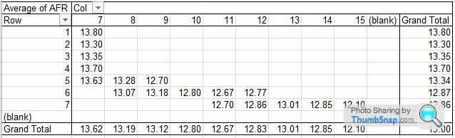

CGCobra said:
(I sometimes like to be able to look at raw data rather than just average readings).
Agreed, plus I have to fill in the row and column numbers above 5,200 rpm’s. Its save to assume once RoverGauge stops logging you're between the last two columns.CGCobra said:
I did notice that where I get the "O2 level in 1/10Per: 10.2" entries in AFR data the records immediately before and after are unrealistically high, typically heading to around 80 before the "O2..." message, I probably need to remove these readings too. I guess the Innovate system gives this reading when data is obviously wrong, Have you any idea why the readings go AWOL?
They typically seem to go out for 3-5 seconds, over a 22min logging period I had 16 "outages". Do you tend to see this level of poor readings (about 5%)?
Only at the end of a full power run test, I’ll explain.They typically seem to go out for 3-5 seconds, over a 22min logging period I had 16 "outages". Do you tend to see this level of poor readings (about 5%)?
You should only see the "O2 level in 1/10Per:" message on overrun when the ECU temporarily cuts the fuel. I’ve disabled this overrun cut below 4,000 rpm in my R3652 and set the AFR between 18 and 20 on the top row to induce overrun cracks & bands, as a result I also don’t see “O2 level in 1/10Per:” message unless I suddenly lift off above 4,000 rpm. This overrun set point is controlled by chip offset 137 and the different values are listed half way down http://www.stevesprint.com/remap-14cux/addresses.h...
Once I finally got my AFR Logger and merger basically working last spring I abandoned working on them as the weather was improving and didn’t bother fixing the on screen error messages as it always carries on logging to file. I really welcome your interesting in my logger & merger as it will give me the kick up the bum I need to fix the “o2 Level messages” plus “Warming up messages” and remove the 0.00 AFR records at the end of the file. We should really remove all records with sudden throttle movement for up to a second afterwards to give the throttle enrichment time to decay.
Maybe we should also automatically remove all overrun records on a closed throttle on rows below 0 or 1 and say above 1,400 rpm, what do you think??
Glyn
Do you prune your AFR logs???
I’ll save the elevated moving idle for another night.
CGCobra said:
I think I could alter my macro to filter based on any combination of readings.
Currently I run a sequence of macros which will eventually be joined but I'll maintain the ability to run 'stand-alone'
I firstly filter the AFR data, chucking out any "Warm up..." and "O2..." readings, any AFR readings earlier than the first RG reading and any AFR readings > 20 (or any other value I set), I then search through each line of RG data and look for the nearest AFR reading (need to change that to nearest higher AFR reading). Any earlier AFR readings are removed (I need to find a way to allow for RG reading which are missing due to too high RPM).
Once I've filtered the data I create the table scan through the data to fill in the cells.
I guess a bit more 'intelligence' could be added to this, to look for steady states with no sudden throttle movement.
I also correct my speed readings in case I want to use this data.
I did warn you its a slippery slop but you seem to be a natural and I’m very impressed with your progress & speadsheet.Currently I run a sequence of macros which will eventually be joined but I'll maintain the ability to run 'stand-alone'
I firstly filter the AFR data, chucking out any "Warm up..." and "O2..." readings, any AFR readings earlier than the first RG reading and any AFR readings > 20 (or any other value I set), I then search through each line of RG data and look for the nearest AFR reading (need to change that to nearest higher AFR reading). Any earlier AFR readings are removed (I need to find a way to allow for RG reading which are missing due to too high RPM).
Once I've filtered the data I create the table scan through the data to fill in the cells.
I guess a bit more 'intelligence' could be added to this, to look for steady states with no sudden throttle movement.
I also correct my speed readings in case I want to use this data.
CGCobra said:
Maybe better still would be to build this into the AFR logger, perhaps add a simple key press (F key probably) on the computer which would control the AFR log writing, maybe invert the screen graphics to indicate when outputting data rather than just reading it, so a quick glance would indicate which mode you're in. If you're going to have a play with your code maybe you could have a think about this?
If you put the following in a batch file you can fire up RG and my AFR logger and start both automatically logging with one click of an icon plus both log files end up in the same directory.cd \????\logs
start /MAX \????\rovergauge.exe –a –l
cd \????\logs\logs
Start “Title” “\????\AFRLogger.exe" lc2log 7
However, I like your great idea to add a stop and start logging toggle key to my AFR logger and would be much better, I’ll try and change the font colour while logging, if not I could try changing the title or appending a L to the readings on the screen. I’ll have a go once its too cold to work in the garage, plus at the same time I’ll fix the “O2... “ warning messages and change the date format to match RoverGauge. Please be patience with me as I’m not in the computer industry and really struggled to write the logger and merger.
It would also be useful if Colin would be kind enough to assign different keyboard accelerators to RoverGauge’s ‘Start log’ and ‘Stop log’ buttons and make it more obvious while its logging, maybe a flashing message just above the 'Injector Duty Cycle' bar.
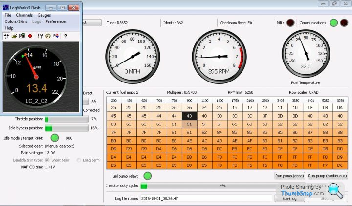
In the mean time if you don’t have a dash AFR gauge you may find Innovate’s LogWorks3 AFR gauge useful.
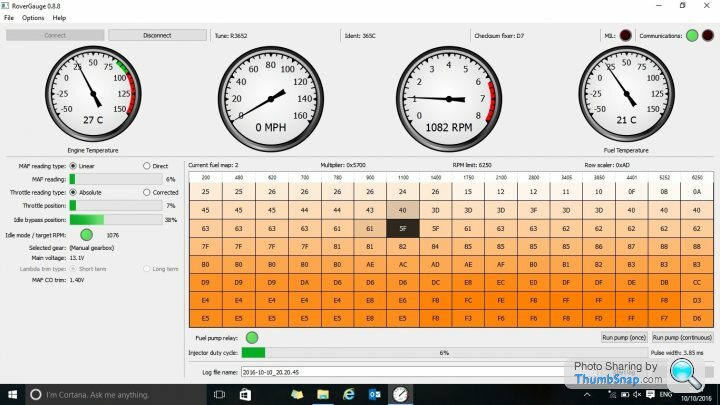
Dave - the Row scalar is from the Chimmy 430BV CAT map and is a perfect fit, Joolz helped me find the main table scalar. It's my latest effort and drives better and the idle never drifts up or down as I've properly lowered the coasting idle by raising offset C242 to 8C (Used to initialize 'stprMtrSavedValue'), my base idle set via the plenum top by-pass screw is 700rpm.
CGCobra said:
Obviously both systems give a time stamp but the AFR logger appears to take readings at a greater frequency (about 4 times)
You can increase RoveGauges log record frequency upto about 6 records a second by reducing the number of sensors logged by disabling them in “Options| Edit settings“While I’m concentrating on remapping the fuel table I normally only have the following enabled;
Road Speed
Engine RPM
throttle Position
Fuel map Data
“Soft” fuel map cell highlight
I sometimes turn off the 'road speed' for power runs but always leave the throttle position on so I can see what I'm doing and filter on it, plus it's also a good way to check your RoverGauge records align correctly with the AFR records.
CGCobra said:
My exhaust system doesn't join at any point so I can only monitor one side at a time, I'm not sure if this is an advantage or disadvantage, probably a bit of both. I
can use the probe in either side though,
During closed loop the left and right lambda’s always run with different percent long term trims, therefore maybe you should do two identical tests with your wideband in each bank and then take the average.can use the probe in either side though,
Cheers, Steve
======== EDIT ========
I can pause logging by pressing my laptop’s sleep button and then pressing any key wakes it up again and luckily continues logging, its worth a try.Edited by stevesprint on Tuesday 4th October 21:06
CGCobra
As requested I’ve sorted the following AFR logger issues and can be downloaded via the previous link above.
1 – Fixed & changed “Warming up” screen message to “Wait”
2 – Fixed & rounded down all “O2 level in 1/10Per:” screen messages to “99.9”
3 - Stopped logging “Warming up” records
4 – Log all “O2 level in 1/10Per:” readings with correct date/time and round down to 99.9.
5 – Added date to every record like RoverGauge (I’ll next fix my merger for date/time)
I've only given the above a very quick test in the garage so please don't hesitate to contact me if you have any issues or any suggestions.
Glyn
Please let me know if any of these changes cause you any issues.
Enjoy
Steve Sprint
RV8 - I'm doing my bit for global warming
Bluebottle said:
Quick question chaps, can rovergauge be run on a windows 10 tablet with a micro usb adaptor?
Sorry don’t know.In theory it should work as I can confirm RoverGauge definitely runs on a Windows 10 64-bit laptop (see below) and tablet USB ports are usually standard USB2 or USB3 compatible, please check the spec.
Also, if the tablet doesn’t output enough power to drive the RoverGauge USB cable controller you may require a powered USB hub.
CGCobra said:
Hi Steve
Sorry not to have been back sooner but been very busy last week and that looks set to continue until about mid November. I'll try and do a run with your new AFR logger at the weekend weather permitting and let you know how it goes.
No rush, it's given me a chance to also fixed my merger so it now works with AFR date and time records like RoverGauge plus I've stopped the zero AFR records top and bottom. I welcome your interest as it’s motivated me to fix some of the smaller annoying issues I never bothered fixing for myself, thanks.Sorry not to have been back sooner but been very busy last week and that looks set to continue until about mid November. I'll try and do a run with your new AFR logger at the weekend weather permitting and let you know how it goes.
Mjstemp1 said:
Hope you don't mind some simple questions. I had a guy make me a version of the "TVR 430 Precat and 450 CAT based on LR R3652 with Extended Fuel Table to 6250RPM" chip from your pages. I have a 4.6L in my MGB and have a NAS ECU and stock O2 sensors and a Wideband also. Issue I am having is RoverGauge comes up with no Codes except "Tune Resistor Out of Range" and then I end up in Map 0 which comes up with low RPM etc. But the Lambda's both show and are move in Short and Long term.
Hi and Welcome, sorry for the delayed response.I’m pleased you've found my 14CUX webpages and answered your own questions, it sounds like you know what you are doing. Hopefully you also found this useful wiring diagram www.remap-14cux.info/14CUX-Wiring.pdf
As you are running stock O2 sensors my "TVR 430 Precat and 450 CAT based on LR R3652 with Extended Fuel Table to 6250RPM” is a good starting point especially if you rev past 5,500rpms. If not, you could try TVR’s OEM map “TVR Chimaera 450 CAT (R2967)” because the Chimaera 450 engine is actually a 4.6 but with 4.0 pistons to increase the compression ratio. Please let me know how you get on as I plan to revisit my "TVR 430 Precat and 450 CAT based on LR R3652 with Extended Fuel Table to 6250RPM” to improve the coasting/slowing down idle.
What wideband sensor do you have? I’ve written a small program that captures my Innovate LC2 wideband AFR readings and outputs to a log file with the system time against each reading, I then merge the AFR reading by the system time with the RoverGauge log to show the AFR against each active fuel table row and column in the log. I finally create an Excel pivot table that shows the AFR for each cell in the fuel table as on the previous page. I maybe able to adapt my AFR logger to work with your wideband sensor, but no promises.
Mjstemp1 said:
So looking at Address 47C1 I see that the Tune Resistor Enable is 00 in the new chip and my stock NAS 3.9L 3652 it was FF. Does this imply I either add a 3900 Ohm from Pin 5 of the ECU to ground or make up a new chip after changing this Address from 00 to FF?
Correct, to run map 5 you need either a 3900 ohms across pin 5 & Ground or you can force map 5 by setting 47C1 to FF as in the NAS tunes. (Dan informed us NAS vehicles don’t have pin 5’s connector in the plug & loom).Mjstemp1 said:
If i download the Chip via Rover Gauge and run the 14CUX Toolkit, Copy Rom 1 to Rom 2 I get a file that looks correct. But where is Map 0 located? How do I get out of it if there are no codes?
I’m sure you’ve realised down loading via RoverGauge give you one copy then need duplicating to flash back to a chip.
I’m sure you now realise Map 0 starts at chip offset 00 or 4000 and is the default map when there is no tune resistor, but its best you force map 5 with either of the methods you correctly worked out.I’m sure you’ve realised down loading via RoverGauge give you one copy then need duplicating to flash back to a chip.
Mjstemp1 said:
May be we could get a spot to store all this info without going through 55 pages and multiple sites?
I plan to update my 14CUX web pages this winter and I’ve registered the domain www.remap-14cux.info . In the mean time should you require any further information please do not hesitate to contact us again.Good Luck and Enjoy,
Steve Sprint
Mjstemp1 said:
Steve,
Thanks for the replys. Was able to get the 3900 ohm resistor installed and working now in Map 5. Having a significant lean stumble based on the AEM wideband when I roll into the throttle around 2000 rpm. Full throttle also is leaner than I would have thought at around 13. Have to figure out how to dataLog from the AEM gauge. Then will try merging etc the files.
I also have an issue with my road speed sensor. VDO gauge with hal sensor and speedo works but ECU not getting signal, have to measure what's coming from the wire. Would lack of road speed cause lean stumble?
Mike
Did your ECU loom already have the wire to pin 5 for the tune resistor?Thanks for the replys. Was able to get the 3900 ohm resistor installed and working now in Map 5. Having a significant lean stumble based on the AEM wideband when I roll into the throttle around 2000 rpm. Full throttle also is leaner than I would have thought at around 13. Have to figure out how to dataLog from the AEM gauge. Then will try merging etc the files.
I also have an issue with my road speed sensor. VDO gauge with hal sensor and speedo works but ECU not getting signal, have to measure what's coming from the wire. Would lack of road speed cause lean stumble?
Mike
How lean and how much throttle????
You shouldn't run lean at 2,000rpm while running closed loop unless you've run out of lambda trim or the throttle is more than 40% or the engine temperature is below 50 deg c which both force open loop. The lambda trims should fluctuate the AFR around 14.7 and gradually decay up to 3,400 rpm.
Here’s the results of my Griff 4.3 this weekend running R3652 map 5 TVR 450CAT, you can see on full load my 430 can’t reach the bottom row of the fuel table and runs rich on full load, but interestingly it drives surprisingly well.

According to Des Hammill “How To Power Tune Rover V8” 13 AFR is best for fully open throttle between Max torque & Max Power, Des Hammill says the following AFRs are proven.
13.5 Idle (for smooth slow speed)
12.5 Accelerating from stand still
13.0 between Max torque & Max Power
15.4 Economy Cursing (Max)
If your AEM wideband outputs human readable AFR readings then try this version of my AFRLogger with the timelog parameter “AFRLogger timelog” but you’ll need to know and select your AEM connection settings from the Settings drop down menu. Its not the finished product but may help identify what’s involved.
www.remap-14cux.info/AFR_Logger.zip
If not you could try taking a video clip of RoverGauge and your AEM Gauge together while driving and avoid sudden throttle movements, or you could bribe a passenger to note down the AFR readings.
We know the road speed has no effect on AFR and the lack of a road speed sensor will cause the engine to stall while slowing down, but not 100% sure if “the lack of road speed cause lean stumble”.
You can see from my favourite wiring diagram the speed signal should be pulsed +12v on pin 6 preferably with diode protection. You'll need roughly 3 or 4 pulses per prop-shaft revolution and for best results the 0 volts & 12v pulses should be similar duration.
Steve
RV8 - I'm doing my bit for global warming
Mjstemp1 said:
Couple of further questions on Datalogging the AEM gauge. Seems it only has analog out put with two wires and 0-5V. What I don't know is what sort of cable I would need for this to input to a USB. Would it be another of the TTL-USB like the RG cable? Their direction are a little vague!
"[WHITE – The WHITE wire should be connected to the Lambda + input on the
EMS or the analog + input on a similar device.
BROWN – The BROWN wire should be connected to the Lambda – input or the
analog – input. If the EMS or similar device does not have a – input, the BROWN wire
should be connected to a sensor ground. If no sensor ground is available, the BROWN
wire should be connected to a power ground. Note: The BROWN wire must be
connected in order to get correct readings from the analog output.]"
Sadly, doesn’t sound like a serial data output that can be connected directly to a computer via a USB cable, you maybe able to connect it to a computer via a data logger."[WHITE – The WHITE wire should be connected to the Lambda + input on the
EMS or the analog + input on a similar device.
BROWN – The BROWN wire should be connected to the Lambda – input or the
analog – input. If the EMS or similar device does not have a – input, the BROWN wire
should be connected to a sensor ground. If no sensor ground is available, the BROWN
wire should be connected to a power ground. Note: The BROWN wire must be
connected in order to get correct readings from the analog output.]"
Mjstemp1 said:
As to the surge/hiccup as I roll on the throttle, not sure what is causing it now. I do not see anything on my TPS that looks out of place. I recall having this also happen when on Map 0. AFR goes lean and then its fine as I continue. Fuel,trim in RG long term is -20 &-40. Plotted Short term trim and at 2000 rpm I get lots of +250 on one side and -100 on the other.
Another basic question, RG fuel map, the engine load is coming from TPS or AFM or a combination of the two?
How lean does the AFR go?Another basic question, RG fuel map, the engine load is coming from TPS or AFM or a combination of the two?
While the throttle is steady or moving slowly the engine load only comes from the AFM, the active row does momentarily jump further down than normal when the throttle opens rapidly and momentarily jumps higher than normal when closing rapidly.
Does the active row change smoothly around at 2,000rpm?
Mjstemp1 said:
Thanks again gents!
Lean stumble is a jump from around AFR of 15 to above 17, feels like motor cut out so the gauge may not be dropping enough actually ! Need to get a passenger to help video, plot etc.
Frustrating on the AEM Analog gauge as they work great as a gauge, data logging leaves a bit to be desired unless feeding into a MS or other ECU. There are modules that could be added to capture and input the 0-5V signal, low end are around $50 USD for any one else with this issue.
Try and reproduce the lean stumble to a RoverGauge log and check if any of the settings suddenly change, for exampleLean stumble is a jump from around AFR of 15 to above 17, feels like motor cut out so the gauge may not be dropping enough actually ! Need to get a passenger to help video, plot etc.
Frustrating on the AEM Analog gauge as they work great as a gauge, data logging leaves a bit to be desired unless feeding into a MS or other ECU. There are modules that could be added to capture and input the 0-5V signal, low end are around $50 USD for any one else with this issue.
mafPercentage
currentFuelMapRow
currentFuelMapCol
lambdaTrimOdd
lambdaTrimEven
pulseWidthMs
The more unnecessary sensors you turn off in "Options|Edit Settings" the more log records you'll get per second.
Good Luck
Steve
Mjstemp1 said:
Mark,
A few years back others had similar findings and it was the XDF for the 14 CUX in TunerPro. Trying figure out if there is a newer XDF that I don't have.
Mark, A few years back others had similar findings and it was the XDF for the 14 CUX in TunerPro. Trying figure out if there is a newer XDF that I don't have.
Sorry for the delay, life keeps me very busy and I wouldn't have it any other way.
I remember and won't mention any names, they admitted off air they were comparing different maps, I'm certainly not suggesting that is your issue. In TunerPro right click on “TunerPro MAP 2 FUEL TABLE – Green” and check Address is 0x4379, then check the table in the bin file at hex 4379 with HexEdit. Do you have an Ostrich emulator and downloaded the bin to TunerPro. If you email me a full screen shot of your TurnerPro & RoverGauge I'll try and help you.
Here’s the latest TunerPro Defination file, although it contains the following extra scalars & table I doubt it will fix your issue.
www.remap-14cux.info/TunerPro-xdf.zip
Tested and work
Coasting Idle Hold Up - increase to lower lingering idle
Cranking Idle Adjust - Adjusts cranking idle across the whole temp range
Cranking Idle Table by Temperature (See notes in TunerPro)
Tested and didn’t see any noticeable difference
Map 2 – Warm Up Threshold
Map 2 – Warm Up Temp Threshold (77 Degc)
Map 2 – Full Load Additive
Map 2 – Deceleration Gain
Mjstemp1 said:
Steve,
That XDF file corrected my issues. Now the Maps between TunerPro and RG match up.
As to the stumble I will continue to investigate. Switched back to map 5 on your "R3652_430_6250_LowBaseIdle" file as the stumble was less pronounced in this Map. Also looked to be running lean on the Map 2.
Saw some strange things while my assistance watched the RG. One time we saw a massive rpm increase to 6200! Too bad we were at 2000. So point towards ignition but what exactly I am not sure. Using a Delco Buick Distributor with Pertronix's module in it and a Pertronix coil. Both are less than a year old and never caused any issues with my old Carb setup. The lead to the ECU is kept at full voltage until inside the car then I split the signal off for my VDO tach and to the ECU where I have the 6800 ohm resistor. I will try a separate lead to the ECU from the coil in case some interference is happening and also add the resistor right at the coil.
Mike
Excellent, I'm pleased TunerPro and RoverGauge now match, sorry must have been a very old XDF file.That XDF file corrected my issues. Now the Maps between TunerPro and RG match up.
As to the stumble I will continue to investigate. Switched back to map 5 on your "R3652_430_6250_LowBaseIdle" file as the stumble was less pronounced in this Map. Also looked to be running lean on the Map 2.
Saw some strange things while my assistance watched the RG. One time we saw a massive rpm increase to 6200! Too bad we were at 2000. So point towards ignition but what exactly I am not sure. Using a Delco Buick Distributor with Pertronix's module in it and a Pertronix coil. Both are less than a year old and never caused any issues with my old Carb setup. The lead to the ECU is kept at full voltage until inside the car then I split the signal off for my VDO tach and to the ECU where I have the 6800 ohm resistor. I will try a separate lead to the ECU from the coil in case some interference is happening and also add the resistor right at the coil.
Mike
How long did you see 6200 rpm for and where you logging??? That certainly would change the active fuel cell and therefore the fueling.
Here's my latest R3652_430_6250 with an improved coasting idle fix and a different cranking idle table. I've ben running it for the last few month and the coasting idle is much better but I'm not sure how it will start in really cold weather? If you get a chance to run it I would appreciate any feed back good or bad.
www.remap-14cux.info/R3652_430_6250_BVCatCrankFixe...
eisdielenbiker said:
Hi,
I have just bought an MG with a 14CUX EFI. I also had some hesitation on accelerating hard at different rpm. One flat spot was around 1700 another in the upper 2000s. After this they were gone at higher revs. At least I didnt noticed them. A new Bosch coil, new HT leads and a more advanced ignition timing of at least 11 degrees at idle cured these problems.
If you allow I would like to ask another question to the experts:
Is it a bad idea to backup the ROM checksum at battery backed up location $54 which seems unused in order to reset the long term lambda trims if an emulated ROM is changed ? I am using an Ostrich 2 emulator and am a little annoyed by ever reconnecting the car battery. I tried my first code change like this and it seems to work:
ldab CHECKSUM_FIXER ;start of my code
cmpb $54 ;potential unused battery backed up ram location
beq .clr_int_ram ;ROM not changed
stab $54
ldd #$8000 ;reset long term trims
std secondaryLambdaR ;as when ECU was disconnected from power suppply
std longLambdaTrimR
std secondaryLambdaL
std longLambdaTrimL ;end of my code
;----------------------------
; Clear internal memory
;----------------------------
.clr_int_ram clra
ldx #$0055 ; *** Zero Memory $54 to $FA ***
ldab #$A5
.zeroRAM_0054 staa $00,x
inx
decb
bne .zeroRAM_0054 ; *** End Zero Memory ***
If it evolves satisfactory I would encapsulate the later original battery ram clear sequence in a subroutine. Possible the stepper motor value should be resetted too . The routine would do that also.
Cheers
Mark L
Mark LI have just bought an MG with a 14CUX EFI. I also had some hesitation on accelerating hard at different rpm. One flat spot was around 1700 another in the upper 2000s. After this they were gone at higher revs. At least I didnt noticed them. A new Bosch coil, new HT leads and a more advanced ignition timing of at least 11 degrees at idle cured these problems.
If you allow I would like to ask another question to the experts:
Is it a bad idea to backup the ROM checksum at battery backed up location $54 which seems unused in order to reset the long term lambda trims if an emulated ROM is changed ? I am using an Ostrich 2 emulator and am a little annoyed by ever reconnecting the car battery. I tried my first code change like this and it seems to work:
ldab CHECKSUM_FIXER ;start of my code
cmpb $54 ;potential unused battery backed up ram location
beq .clr_int_ram ;ROM not changed
stab $54
ldd #$8000 ;reset long term trims
std secondaryLambdaR ;as when ECU was disconnected from power suppply
std longLambdaTrimR
std secondaryLambdaL
std longLambdaTrimL ;end of my code
;----------------------------
; Clear internal memory
;----------------------------
.clr_int_ram clra
ldx #$0055 ; *** Zero Memory $54 to $FA ***
ldab #$A5
.zeroRAM_0054 staa $00,x
inx
decb
bne .zeroRAM_0054 ; *** End Zero Memory ***
If it evolves satisfactory I would encapsulate the later original battery ram clear sequence in a subroutine. Possible the stepper motor value should be resetted too . The routine would do that also.
Cheers
Mark L
Welcome and thanks for your really neat idea to automatically reset the battery saved data when changing proms, you soon got your head around Dan’s rebuild project. I personally will find your solution very useful as I’m bored of disconnecting my battery to reset the ECU even though I have a quick battery disconnect terminal, I much prefer you automatic software solutions. Yes I would also include stprMtrSavedValue that is copied from C242 during ECU battery power reset.
This is really a question for Dan, DaveP or Colin but I’ll have ago.
I see you’ve changed
ldx #$0054 ; *** Zero Memory $54 to $FA ***
to
ldx #$0055 ; *** Zero Memory $54 to $FA ***
so address $0054 doesn’t get cleared at restart
I’m concerned as I think address $0054 may actually be used as follows:
$0054 is copied to $0052 in idleControl (throttle pot min)
$0054 is subtracted from TPmin in throttlePot.asm
$0054 is copied to $0052 TPmin in shutDown.asm
I’m not an assembler programmer so would this mean Mark L checksum would be
copied to $0052 in idleControl (throttle pot min)
subtracted from TPmin in throttlePot.asm
copied to $0052 TPmin in shutDown.asm
Dan, DaveP or Colin help Please !!!
As $0054 is normally always zero could we comment out the three uses of $0054 above ???
Thanks, Steve
Edited by stevesprint on Saturday 12th November 21:51
danbourassa said:
Mark L, I'm so glad that you are taking an interest in the assembler code. There is a lot that is not fully understood yet, so any help is appreciated.
Obviously, you realized that the actual battery preserved area is 32 bytes long and extends to $005F. The 14CUX code only uses $0040 through $0053 in this way and the rest is treated like normal volatile RAM.
Steve is correct about the fact that $0054 is actually used as a throttle pot minimum value. This is for the throttle pot self-learning feature. I know how the confusion happened and it's my fault. I just looked at file 'ramLocations.asm' and noticed that I never assigned a variable name to location $0054. Maybe the mistake happened because location $0053 is actually reassigned after it is no longer needed as a checksum, so it has two assigned names.
Using the end of the stack area is clever and probably safe to do. I assume you would shorten the memory clearing loop to use this location.
Just for a little history on this, it may not be obvious to everyone that all names in the code (both variables and routines) were assigned by me in order to not only make it readable but to also make it modifiable. The dissassembler only knows address locations. At first, I was able to re-assemble and get back to the original code only without any changes. Adding something as innocuous as a single NOP (no operation) which would normally just burn a couple of clock cycles would shift everything downstrean of the NOP by a single byte and invalidate all of the hard-coded labels. Although I kept everthing in its original order for the sake of binary comparisons, we should now be able to shuffle code routines and RAM locations (with a few limitations). The assembler does two passes on the code. The first pass resolves label locations. The labels are then converted to actual memory locations and plugged in on the second pass.
Dan,Obviously, you realized that the actual battery preserved area is 32 bytes long and extends to $005F. The 14CUX code only uses $0040 through $0053 in this way and the rest is treated like normal volatile RAM.
Steve is correct about the fact that $0054 is actually used as a throttle pot minimum value. This is for the throttle pot self-learning feature. I know how the confusion happened and it's my fault. I just looked at file 'ramLocations.asm' and noticed that I never assigned a variable name to location $0054. Maybe the mistake happened because location $0053 is actually reassigned after it is no longer needed as a checksum, so it has two assigned names.
Using the end of the stack area is clever and probably safe to do. I assume you would shorten the memory clearing loop to use this location.
Just for a little history on this, it may not be obvious to everyone that all names in the code (both variables and routines) were assigned by me in order to not only make it readable but to also make it modifiable. The dissassembler only knows address locations. At first, I was able to re-assemble and get back to the original code only without any changes. Adding something as innocuous as a single NOP (no operation) which would normally just burn a couple of clock cycles would shift everything downstrean of the NOP by a single byte and invalidate all of the hard-coded labels. Although I kept everthing in its original order for the sake of binary comparisons, we should now be able to shuffle code routines and RAM locations (with a few limitations). The assembler does two passes on the code. The first pass resolves label locations. The labels are then converted to actual memory locations and plugged in on the second pass.
You always manage to dive in and rescue me when I’m getting out of my depth, thank you. I’m also glad Mark L is interested in the code and I'm sure we’ll all learn more together as he is renewing our interest in the code with his new ideas.
Dave explained to me a long time ago about the symbol tables you created with all the variable and routine names you invented so the reversed engineered machine code is
Back to business
Dan, I see you are right only 32 bytes, According to the M6803U4 spec sheet below there are only 32 bytes of retainable RAM when powered down, therefore I would have thought near the end of the stack $EF is passed the RAM retained when powered down, ($0040 + 32 byte = $005F). If this is correct could Mark move one of working varables out of the retained RAM to free up a retained byte for the checksum fixer?
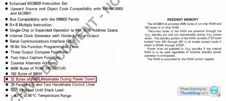
Mark, you can download all Dan's data sheets from www.remap-14cux.info/RebuildProject including this MC6803U4.pdf, they are sure to send you to sleep at night.
Edited by stevesprint on Saturday 12th November 21:13
Dan
Please confirm I've interpreted the folowing code correctly as it appears $0054 isn't actually updated/modifed where as throttlePotMinimum($0051/$0052) is re-calculated in throttlePot.asm or am I missing something?
idleControl.asm === $0054 copied to $0052 (throttle pot min)
ldaa $0054 ; throttle pot min
staa $0052 ; throttle pot min (battery saved)
throttlePot.asm === Subtracts value at $0054 from Accumulator A
suba $0054 ; the 8-bit TPMin working value??
shutDown.asm === $0054 copied to $0052 (throttle pot min)
ldaa $0054 ; load working value of Throttle Pot Minimum (TPmin)
staa $0052 ; store TPmin in battery backed RAM
davep said:
danbourassa said:
...I'm almost convinced that this is a completely useless sub-system and what I think should be done is the removal of the purge valve interrupt and all its related subroutines from the code.
There is one thing that could make me hesitate on this. Has anyone ever had a purge valve fault (code 88) and successfully fixed it by replacing the valve or canister?
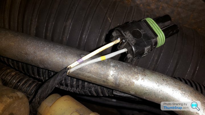
Dan, since a good number of TVR owners have pruned the carbon canister and associated purge valve hardware out of the system I would expect fault code 88 to be commonplace. In these cases it's a shame that the 14CUX MPU is overlooked and remains burdened with having to comply with the purge interrupt, monitor HO2S levels, etc, etc, when in closed loop! I've looked for the earliest and most convenient point in the flow to take the purge code out but it's complicated by the fact that the main purge subroutine is called from other places, ECT for instance. Is it possible to simply disable the IRQ2 interrupt by tweaking the four purgeValveInt vectors in vectors.asm or is it hard coded?There is one thing that could make me hesitate on this. Has anyone ever had a purge valve fault (code 88) and successfully fixed it by replacing the valve or canister?
Here's my unused purge valve connector
Gassing Station | Griffith | Top of Page | What's New | My Stuff