Removing Top Ball Joints
Discussion


I'm just adjusting my Camber on the front suspension and I am having a really hard time getting the top ball joints off to adjust them. Managed to get one off using a steel chisel as a wedge, but the other side won't budge.
Is there a technique for removing them easily? Car hasn't even been on the road yet and they have also been greased during assembly.... Don't fancy trying to remove them again in 5 years time!
Cheers,
Mart
Is there a technique for removing them easily? Car hasn't even been on the road yet and they have also been greased during assembly.... Don't fancy trying to remove them again in 5 years time!
Cheers,
Mart
The diagram is how mine are built with the addition of a set nut on the inside which is there only to insure that the threaded insert does not back off. In addition, my fabricator installed heims on the inboard mounts that allow us to adjust caster. The a arm is a all new piece made from 4130 steel and appropraitly rated heims. Part of this was prompted by the K/N Teams excperince with thier car at Daytona were the upper ball joints failed from transistioning to the banking. Another input was from Jeff Schwartz he has modified his car by changing the lenght of the rear leg of the upper A arm to inrease caster from 3-4 degrees from the factory to a higher value. I will let Jeff make any further comments about that mod. Now before someone gets on here and rants and raves about why did the A arm fail "oh my god that proves the whole car is worthless" lets remember that race cars are developed not hatched.I saw the K/N car run at california speedway in the IMSA races and the car was top 3 fast for the day in practice. When I got the chance through friends to talk to the K/N crew cheif about his opinion of the car, his chief complaint was "the car is to small to package all the STUFF that goes into a modern race car and the fuel load burn changes the C.G. of the car to much to keep the car's handling consistant from full tanks to empty. Anyone intrested in seeing the arms ect. can e mail me at E mail listed and I will forward some pictures. Someday when I get alot smarter I am going to understand how to post pictures on here. Lee
Davrianman said:
How about this as an alternative to the existing setup?
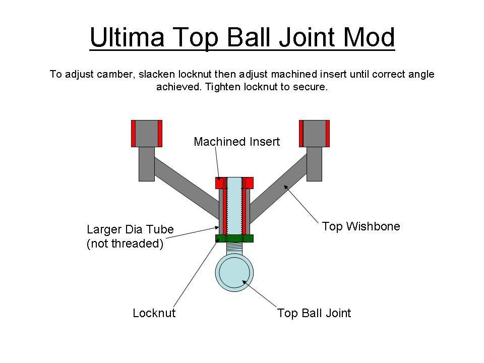
Is there any reason why it would not work? Moding the wish bones will not be easy, but you could make a jig to re-position them correctly...
What do you think?
Mart
Is there any reason why it would not work? Moding the wish bones will not be easy, but you could make a jig to re-position them correctly...
What do you think?
Mart
Mart,
It looks like it would work. The addition of another lock nut to lock the sleeve may remove the need for the lock wire. Still - belts and braces are good.
I think the design is putting a lot of material into the A arms. can you rationalize the design some more to remove some of the weight and maybe get the force lines between the pivot points in a straight line, rater than canted between the various tubes.
Regards Ryan

GTRCLIVE said:
Ah got you, its a Mounting for the Rad frame... which is detachable and adjustable...
dam and bugger, you would not believe the crazy ideas my mind was trying to rationalise as an anti roll bar, driven of that clevis. Cant seem to get any that work that are not massively complicatedGassing Station | Ultima | Top of Page | What's New | My Stuff