R400D to R500D Anyone done it?
Discussion


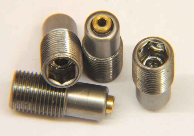
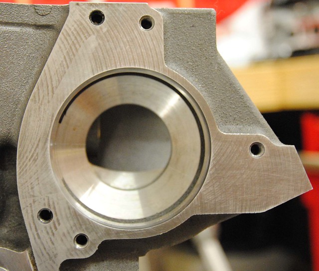
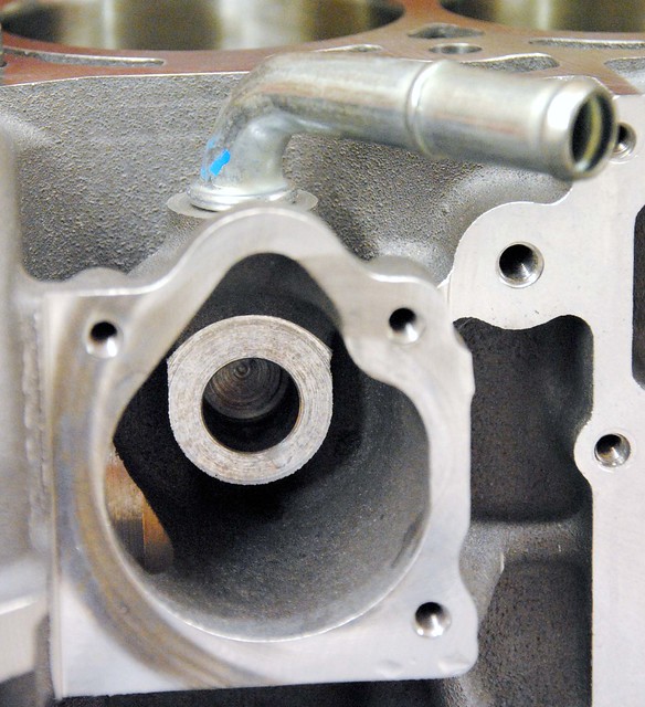
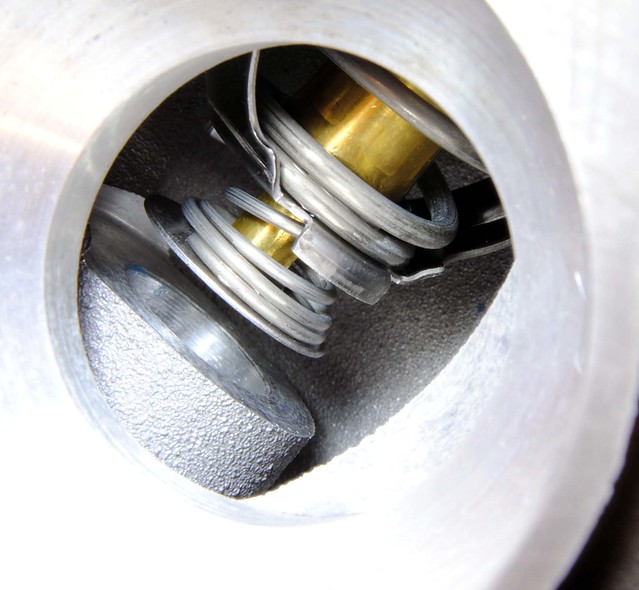
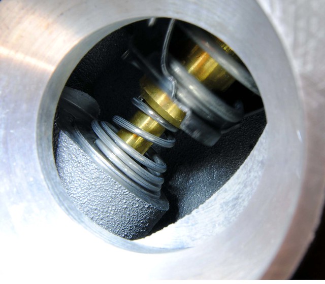
With the crank sent off to be keyed and a load of parts on order, I spent some time looking at the block in more detail. These little ‘squirters’ hide on top of the main bearing journals and spray oil onto the pistons and bores when the oil pressure is high enough. They have spring loaded ball bearing valves in them.
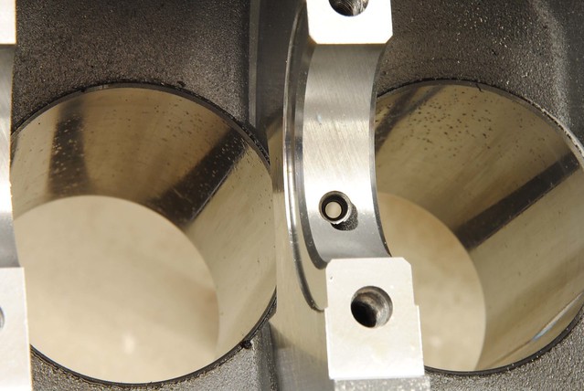
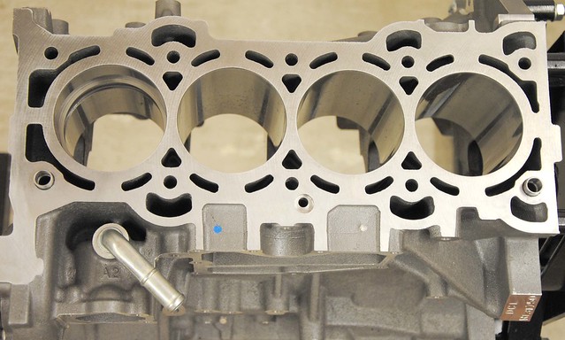
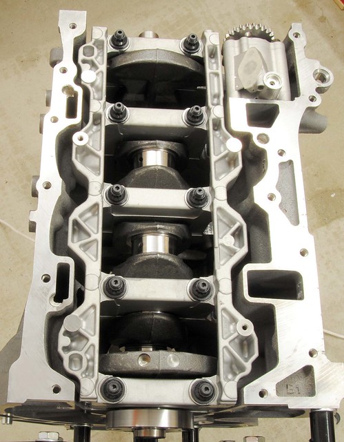
Duratec is a very straightforward 'back to basics' type engine. But look how they put the 'basics together! The complexity in the block casting, particularly in the voids, is outstanding - Just look how the liners meet the head surface to provide a trouble free gasket surface.
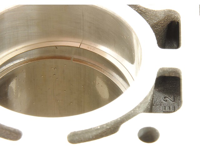
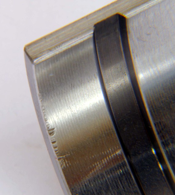
As I mentioned in a previous post, uprated main bearings are not readily available for the Duratec. The preferred option is to use the Ford graded bearing. This picture offers a clue as to why this may be - the bearing material is VERY thin. No doubt the this adds significantly to the structural strength of the bearing, but does show the importance of those 13 possible grade options to get the tolerances correct.
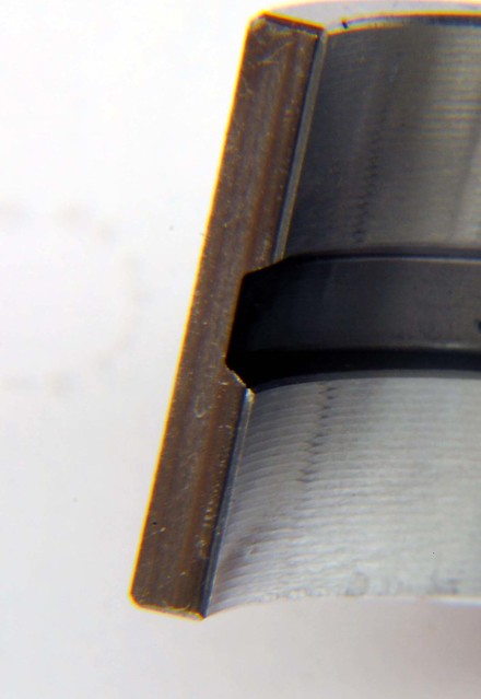
One disappointment when examining the bearings was to see that some had suffered minor hammer marks and scuffing. I'm 100% confident this damage happened during or before the original assembly, and my experience suggest it's irrelevant, but when you aiming for a perfect build it is unwelcome
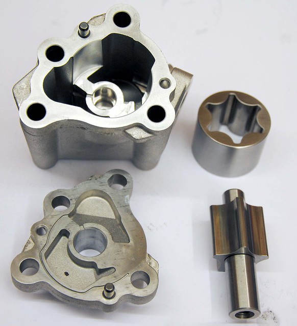
The oil pump is a fairly standard rota type. As I am using a Cosworth dry sump I’ll be using the internal oil pump. The jury is still out on whether I upgrade to a high volume version.
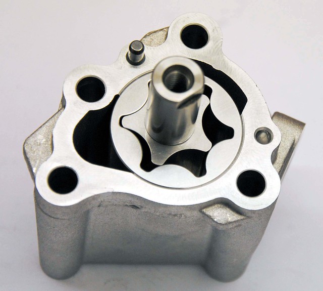
Anyone who has pushed a Duratec for a long track session will have seen that oil pressure can take a dive - but it usually recovers quickly. One theory is that the block expands and allowing more oil to escape from the mains. The more I look at the overall oil system, the more I realise that the main bearings (and their tight tolerances) are key to this engine’s success.
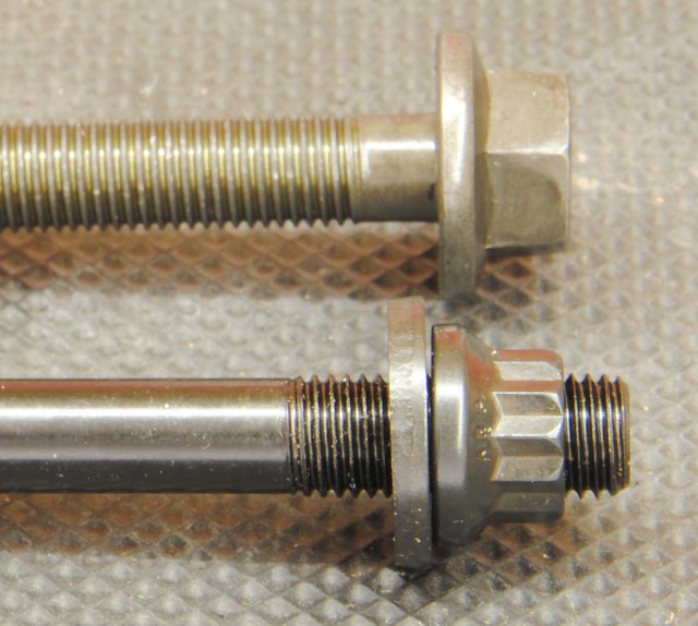
While on the subject of oil pressure, it is worth saying that the main studs will be replaced with ARP versions. Their increased strength over the standard bolt help to hold the bearing together and play their part in maintaining tolerance and the oil pressure. At £16 a bolt, they're expensive but probably worth every penny.
In the next post, I hope to start assembly - you can follow day to day stuff on https://www.facebook.com/Duratec.in.detail
Duratec is a very straightforward 'back to basics' type engine. But look how they put the 'basics together! The complexity in the block casting, particularly in the voids, is outstanding - Just look how the liners meet the head surface to provide a trouble free gasket surface.
As I mentioned in a previous post, uprated main bearings are not readily available for the Duratec. The preferred option is to use the Ford graded bearing. This picture offers a clue as to why this may be - the bearing material is VERY thin. No doubt the this adds significantly to the structural strength of the bearing, but does show the importance of those 13 possible grade options to get the tolerances correct.
One disappointment when examining the bearings was to see that some had suffered minor hammer marks and scuffing. I'm 100% confident this damage happened during or before the original assembly, and my experience suggest it's irrelevant, but when you aiming for a perfect build it is unwelcome
The oil pump is a fairly standard rota type. As I am using a Cosworth dry sump I’ll be using the internal oil pump. The jury is still out on whether I upgrade to a high volume version.
Anyone who has pushed a Duratec for a long track session will have seen that oil pressure can take a dive - but it usually recovers quickly. One theory is that the block expands and allowing more oil to escape from the mains. The more I look at the overall oil system, the more I realise that the main bearings (and their tight tolerances) are key to this engine’s success.
While on the subject of oil pressure, it is worth saying that the main studs will be replaced with ARP versions. Their increased strength over the standard bolt help to hold the bearing together and play their part in maintaining tolerance and the oil pressure. At £16 a bolt, they're expensive but probably worth every penny.
In the next post, I hope to start assembly - you can follow day to day stuff on https://www.facebook.com/Duratec.in.detail
I'm still waiting for the crank to be returned and a load of bits, but here's an up date of some of the learning process I am going through with the Duratec . . .
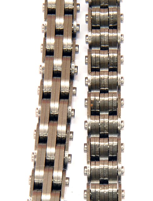
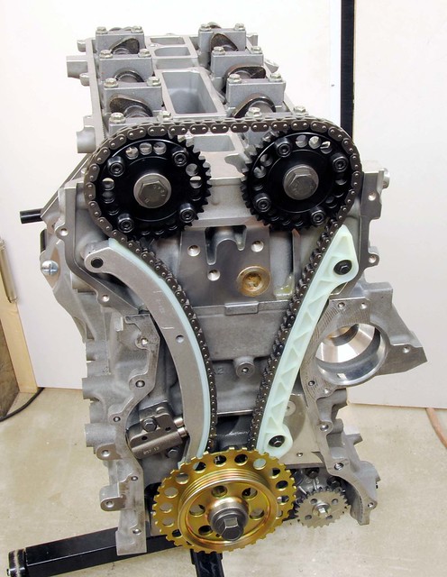
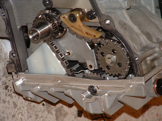
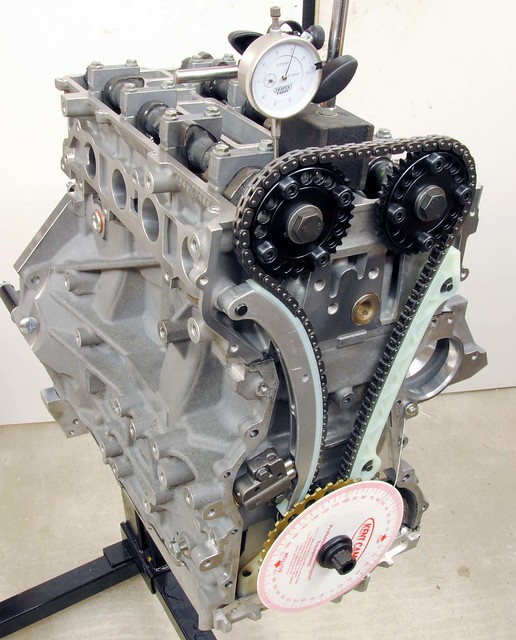
It was fashionable for DOHC engines to have cam belts as they provided a easy solution to the longer runs and high RPM. But with higher production costs to keep the belt clear of oil, it was only a matter of time before the chains made a comeback. The Duratec uses an eight segment design, and, unlike a conventional chains, the segments engage directly with the sprocket. Typical of this engine, it is a clever low cost solution.
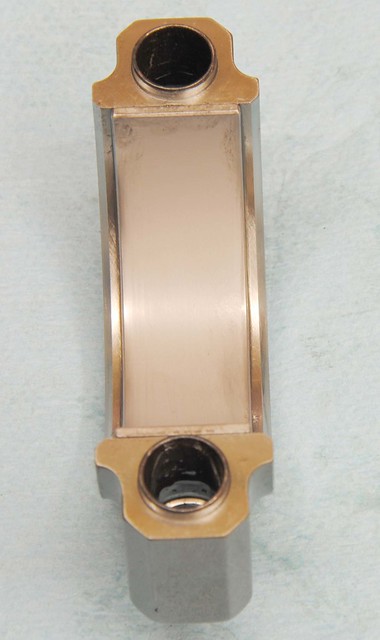
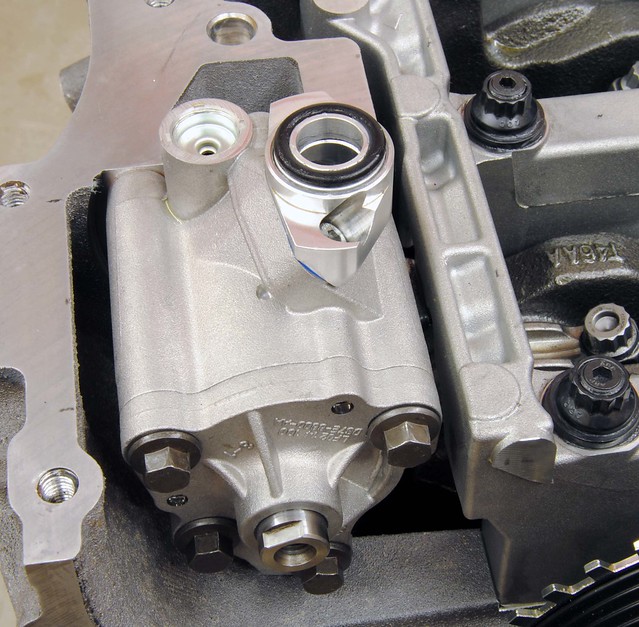
Following on from the chain, the standard tensioner (bottom in the picture) is spring loaded device that also utilises oil pressure. There is a spring ratchet mechanism that takes up the slack when the engine is not running and a small hole in the nose that squirts oil onto the chain (through a hole in the guide).
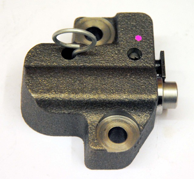
Before I had the dry sump, I lost oil pressure on my R400 and there was a terrifying noise - not a knock like you might expect from bearings, but more like a 'bag of spanners'. I suspect the ratchet mechanism was defeated and the chain lost tension. I got away with it on the ‘standard’ engine but that might not be the case with hotter cams and higher CR piston.
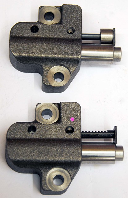
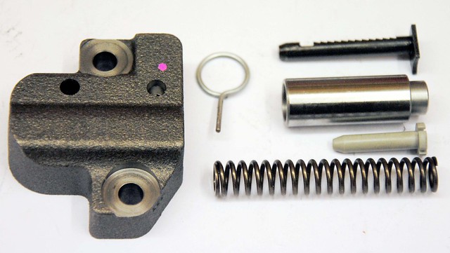
The solution is a modified tensioner (top picture) - there are variations on the theme, but basically a mechanical stop is added to limit how slack the chain can get. This one also has the ratchet machined off completely.
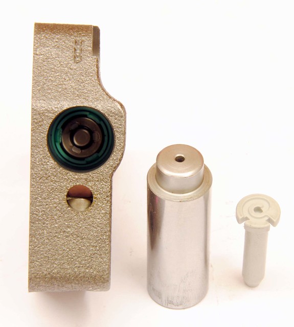
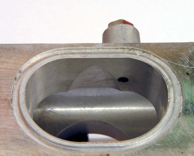
Here's a picture of the tensioner showing the internal valve. The valve inside appears to be 'on-way' and, using the spring, regulates oil flow when pressure is low. Because the spring acts to both tension the chain and regulate the oil pressure, the spring tension will be replaced (and not added to) when oil pressure is sufficient. Also, as the piston would be full of oil with the only exit via the small hole in the tip (non-return valve the other end), it will act as a damper and help keeps the tension guide in contact with the chain.
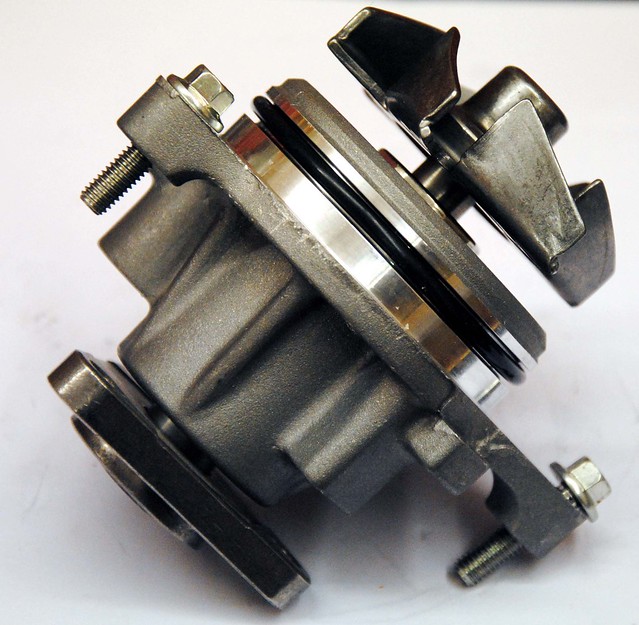
The water pump is a conventional set-up. The cone shape impeller fits in a cone shape that has been machined in the block - coolant being sucked into the centre and thrown out to a ring in the housing - not unlike a turbo charger in appearance. The coolant exiting from the pump is split in two - one flow being directed to each side of the block for even cooling. On a high RPM engine it will cavitate, so steps need to be taken to slow it down and this can be done with either with a larger pulley on the pump or a smaller one on the crank.
The thermostat is 'conventional' (that's a word that I'm using a lot on this engine) but, as is often the case with the Duratec, there's usually a twist to the design. . .
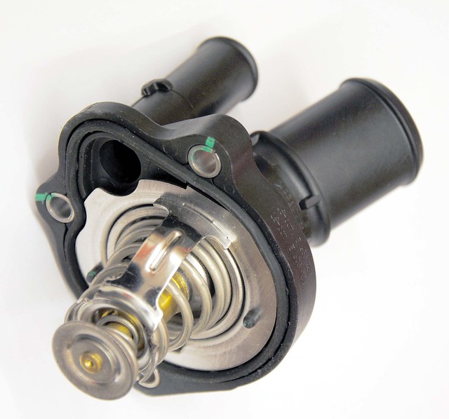
The thermostat housing has a re-circulation pipe that allows for coolant to circulate around the block when the thermostat is closed. The thermostat is, in fact, a two-way valve and blocks off the re-circulation pipe when it opens. The bottom picture shows the thermostat after being heated up in boiling water. This engine will use a 82 degree thermostat.
It was fashionable for DOHC engines to have cam belts as they provided a easy solution to the longer runs and high RPM. But with higher production costs to keep the belt clear of oil, it was only a matter of time before the chains made a comeback. The Duratec uses an eight segment design, and, unlike a conventional chains, the segments engage directly with the sprocket. Typical of this engine, it is a clever low cost solution.
Following on from the chain, the standard tensioner (bottom in the picture) is spring loaded device that also utilises oil pressure. There is a spring ratchet mechanism that takes up the slack when the engine is not running and a small hole in the nose that squirts oil onto the chain (through a hole in the guide).
Before I had the dry sump, I lost oil pressure on my R400 and there was a terrifying noise - not a knock like you might expect from bearings, but more like a 'bag of spanners'. I suspect the ratchet mechanism was defeated and the chain lost tension. I got away with it on the ‘standard’ engine but that might not be the case with hotter cams and higher CR piston.
The solution is a modified tensioner (top picture) - there are variations on the theme, but basically a mechanical stop is added to limit how slack the chain can get. This one also has the ratchet machined off completely.
Here's a picture of the tensioner showing the internal valve. The valve inside appears to be 'on-way' and, using the spring, regulates oil flow when pressure is low. Because the spring acts to both tension the chain and regulate the oil pressure, the spring tension will be replaced (and not added to) when oil pressure is sufficient. Also, as the piston would be full of oil with the only exit via the small hole in the tip (non-return valve the other end), it will act as a damper and help keeps the tension guide in contact with the chain.
The water pump is a conventional set-up. The cone shape impeller fits in a cone shape that has been machined in the block - coolant being sucked into the centre and thrown out to a ring in the housing - not unlike a turbo charger in appearance. The coolant exiting from the pump is split in two - one flow being directed to each side of the block for even cooling. On a high RPM engine it will cavitate, so steps need to be taken to slow it down and this can be done with either with a larger pulley on the pump or a smaller one on the crank.
The thermostat is 'conventional' (that's a word that I'm using a lot on this engine) but, as is often the case with the Duratec, there's usually a twist to the design. . .
The thermostat housing has a re-circulation pipe that allows for coolant to circulate around the block when the thermostat is closed. The thermostat is, in fact, a two-way valve and blocks off the re-circulation pipe when it opens. The bottom picture shows the thermostat after being heated up in boiling water. This engine will use a 82 degree thermostat.
mic said:
Its worth checking that there is enough clearance between the ARP mains bolts and the windage plate. For what its worth the standard bolts will give no trouble at all.
Thanks for the tip! I've just checked them and they are about 1cm longer. It is a Cosworth dry sump and as the studs are also Cosworth (but made by ARP). I would like to think they have taken this into account! (famous last words  )
) Have you gone for a water rail? I went for a dunnell one which is great and sits under the exhaust manifold rather than above it( heat rises?) the only problem was I need to find a separate bracket for the coil pack...unless your using individual ones?
The only thing I'm not happy with is I made a pipe up for the water bypass picture above (turns 90 deg) and has a few joins in, would maybe like to get a silicon one made up for it.... shall wait to see what you do!
Just fitting a new Digi dash and currently putting the new sensors on, the only one I am having trouble with is a oil temp sensor was thinking of putting it in the race line oil filter holder jobbie...but there doesn't seem like there is that much room. Are you bothering?
That looks like a neat solution. I've not decided how I will do mine yet, but have looked at a few options. I've COPs but the issues for me is that I am using a Modine oil cooler and that needs a good supply of coolant. So with that and the by-pass pipe, I need two outlets on the inlet side and none of the water rails I've looked seem to do that very well. The set up I've got at the moment (Silicon pipe on inlet side) works well so may just stick with that until I find something better.
I'm using SPA guage for the oil (sensor in the dry sump tank), and Stack dial gauges for the pressures. Both work well. I particuarly like the SPA as I can set mins and max temps to a warning light.
I'm using SPA guage for the oil (sensor in the dry sump tank), and Stack dial gauges for the pressures. Both work well. I particuarly like the SPA as I can set mins and max temps to a warning light.
Ah I see, I'm running out of space for the oil temp sensor, just been looking at it, have on of these
http://www.raceline.co.uk/products/part_section.as...
But where the sensor fits in, which is about the same size as a vdo there isn't much room left... was going to tap a hole at the end.... might not bother now..never need oil temp before.
http://www.raceline.co.uk/products/part_section.as...
But where the sensor fits in, which is about the same size as a vdo there isn't much room left... was going to tap a hole at the end.... might not bother now..never need oil temp before.
I suppose it depend on your state of tune, how you drive, and ambient temperature, but I personally have never seem high oil temperature on my Duratec. Funny what you say about the alternator position - mine has allways been on the inlet side, but I was thinking of moving it to the exhaust side as the small SBD crank pulley I plan to use makes the belt to belt clearance a bit small 
It was like Christmas all over again with lots of goodies arriving from Sb Developments , but most importantly the crank is back. I'm now looking forward to to putting things back together instead of taking them apart.
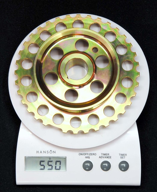
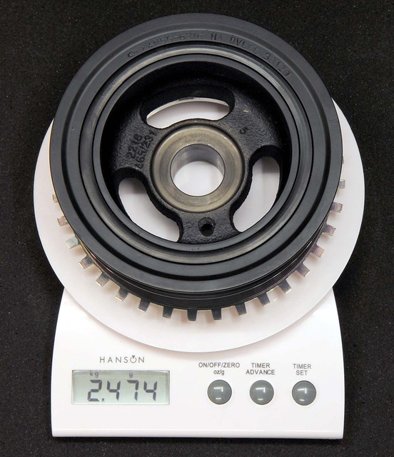
To go with the keyed crank is the Sb Developments small pulley. The standard pulley is 2 KG heavier. Apart from the obvious advantages of reduced mass, I'm curious about the impact this will have on the inherent vibration of an 'in-line' 4 cylinder engine. No doubt the heavier pulley helps to smooth things out, but does it add to, or reduce, the stresses in the crank?
It was always my intention to 'blue print' the engine so a bit of time was spent positioning the main shells on the webs. The Ford assembly guide gives measurements to center the shells to the oil holes in the crank. The block casting is not perfect, so you can't rely on centering the shell on the web to get this right.
A little care here will maximise oil flow to the big ends.
The ladder is treated the same way, but, as it is also machined and honed in-situ, the final tweak is to align it with the block before torquing down.
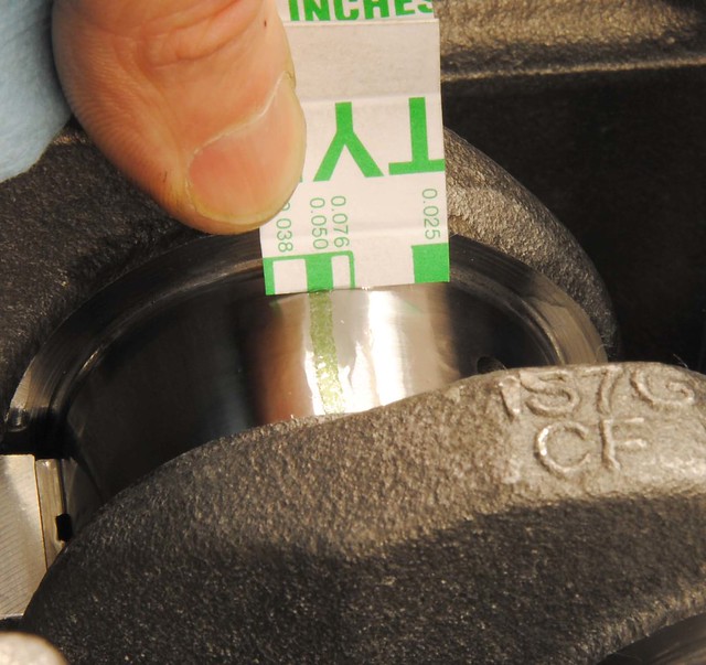
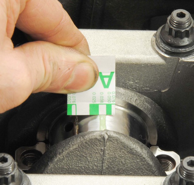
I am using the the original graded Ford bearings and there's little I can do to change clearances. But better the devil you know, so I checked them with Plastigauge. Much to my relief all the bearings produced identical measurements and all nicely square. The clearances were bigger than the Ford declared spec of 0.039 mm - probably due to me only using half the specified torque for the check. I am happy, however, that the full 60 ft-lbs on the ARP studs squeezed this up tighter, and it felt 'nice'. I've used Millers Assembly Lubricant this time (I normally use engine oil). Starting it for the first time may be interesting as it is really thick sticky stuff!
And finally all back in place and torqued up
To go with the keyed crank is the Sb Developments small pulley. The standard pulley is 2 KG heavier. Apart from the obvious advantages of reduced mass, I'm curious about the impact this will have on the inherent vibration of an 'in-line' 4 cylinder engine. No doubt the heavier pulley helps to smooth things out, but does it add to, or reduce, the stresses in the crank?
It was always my intention to 'blue print' the engine so a bit of time was spent positioning the main shells on the webs. The Ford assembly guide gives measurements to center the shells to the oil holes in the crank. The block casting is not perfect, so you can't rely on centering the shell on the web to get this right.
A little care here will maximise oil flow to the big ends.
The ladder is treated the same way, but, as it is also machined and honed in-situ, the final tweak is to align it with the block before torquing down.
I am using the the original graded Ford bearings and there's little I can do to change clearances. But better the devil you know, so I checked them with Plastigauge. Much to my relief all the bearings produced identical measurements and all nicely square. The clearances were bigger than the Ford declared spec of 0.039 mm - probably due to me only using half the specified torque for the check. I am happy, however, that the full 60 ft-lbs on the ARP studs squeezed this up tighter, and it felt 'nice'. I've used Millers Assembly Lubricant this time (I normally use engine oil). Starting it for the first time may be interesting as it is really thick sticky stuff!
And finally all back in place and torqued up
Edited by DCL on Saturday 25th January 11:31
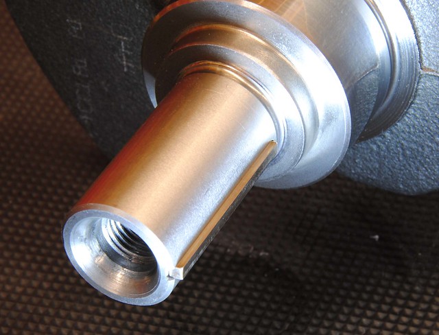
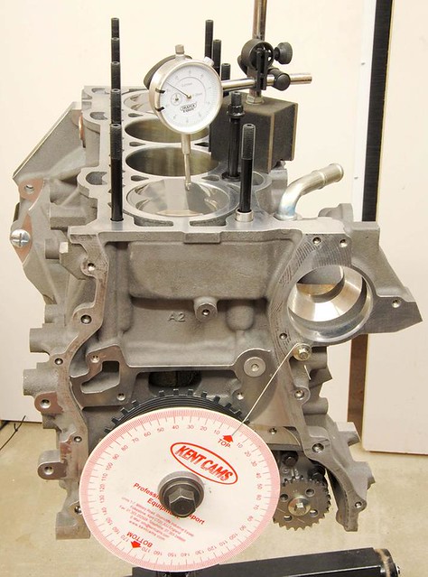
The Duratec crank has a flat ground on one of the counter weights. This is to calibrate it for use with the TDC peg which screws into the block.
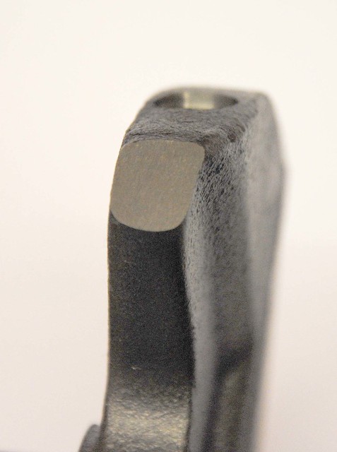
I made one up while with a 10 mm bolt - carefully grinding it to the correct length. It does make life easier for setting things up and is worth the effort.
Time to move on to the pistons assembly. First thing was to gap the rings - all were bang smack in the middle of tolerance for 250 BHP engine, so it didn't take long.

The second ring has a groove at it's bottom edge - the exact function of this groove is up for debate, but it's likely to help with reducing oil passing upwards and provide a downward pumping action. The flow of oil past piston rings is an interesting subject if you like that sort of thing.

The oil expander ring has a ridge too - this time it is clearly for the retaining rings to hold it in place.

I am Using 12.5 CR Supertech pistons and Carrillo (Cosworth) rods. Ford specify a weight tolerance between their standard pistons that amounts to approximately 3 grams. The Supertech pistons were within 2 grams of each other and the Carrillo rods were within a gram. The gudgeon pins were identical in weight. By grading and matching the components I manage to get each piston assembly to within a gram of each other. The new piston and rods are 66 grams lighter than the standard items.


All four pistons assembled, which was straightforward, except for maybe the cir-clips which are always tricky if you haven't got the right tool. But my confidence took a knock when I was left with two circlips. Self-doubt took over and I had to remove all the pistons to check! But all were present and correct - very funny Supertech
The bearing shells are uprated VP from Cosworth.
I used plasti gauge to check them - all being near the 0.038 mm band which is again in the middle of the Cosworth (and Ford) spec. Not quite as even as the mains, but all well within tolerance.
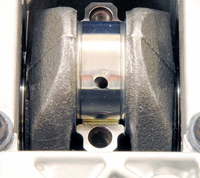
It is worth noting that the bearings look narrower than the cap, in fact, I think it is 2.5 mm. This coupled with a groove in the crank journal provides a reservoir of oil in the bearing and helps to protect the bearing at times of low pressure by allowing oil to recirculate as the hydrodynamic pressure goes negative on the unloaded side. A feature that, prehaps, makes the Duratec a little more tolerant of low oil pressure.
I did get Simon, at Ultimate Performance, to assemble the head after the CNC work (mainly to stop the hassle or ordering cam followers) but I do intend to 'reassemble' it my self. But with the pistons in, it meant I could check the valve-to-piston clearance.
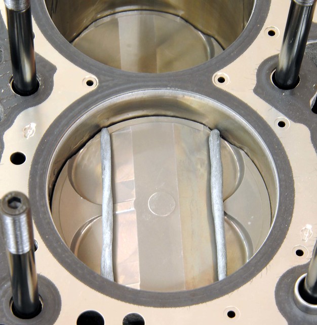
So with some blue tack on no.1 piston, the head was put on with an old gasket, cams timed, and then the crank rotated.
There was no hard contact (relief!) and so the head was removed to see how close things got.
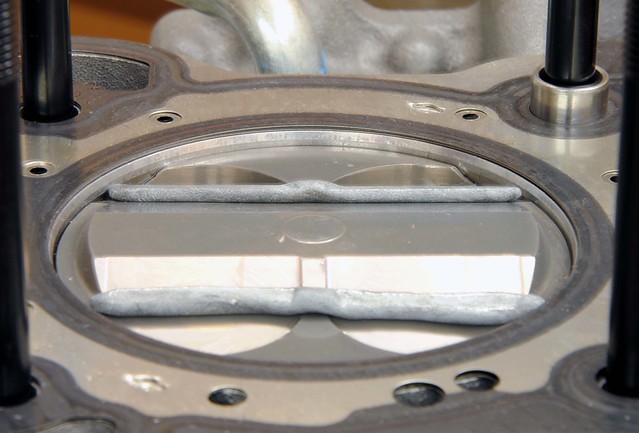
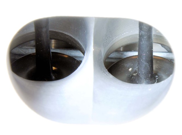
Nothing was too close and amazingly you could see it all happen through the inlet port!
With clearance check done, time was spent dismantling the head and putting it back together. It is not that I don't trust Ultimate Performance to do it right, it was just that I wanted to go through the full process of the engine build myself. But full marks to Simon at Ultimate Performance - every valve was perfect


I was glad to spot this nasty bit of shaving firmly embedded in the cam bearing. It was very hard so probably debris from the valve seat machining - maybe during manufacture at Ford. I levered it out to leave just an indentation which I'm sure will do no harm.

I made one up while with a 10 mm bolt - carefully grinding it to the correct length. It does make life easier for setting things up and is worth the effort.
Time to move on to the pistons assembly. First thing was to gap the rings - all were bang smack in the middle of tolerance for 250 BHP engine, so it didn't take long.
The second ring has a groove at it's bottom edge - the exact function of this groove is up for debate, but it's likely to help with reducing oil passing upwards and provide a downward pumping action. The flow of oil past piston rings is an interesting subject if you like that sort of thing.
The oil expander ring has a ridge too - this time it is clearly for the retaining rings to hold it in place.
I am Using 12.5 CR Supertech pistons and Carrillo (Cosworth) rods. Ford specify a weight tolerance between their standard pistons that amounts to approximately 3 grams. The Supertech pistons were within 2 grams of each other and the Carrillo rods were within a gram. The gudgeon pins were identical in weight. By grading and matching the components I manage to get each piston assembly to within a gram of each other. The new piston and rods are 66 grams lighter than the standard items.
All four pistons assembled, which was straightforward, except for maybe the cir-clips which are always tricky if you haven't got the right tool. But my confidence took a knock when I was left with two circlips. Self-doubt took over and I had to remove all the pistons to check! But all were present and correct - very funny Supertech
The bearing shells are uprated VP from Cosworth.
I used plasti gauge to check them - all being near the 0.038 mm band which is again in the middle of the Cosworth (and Ford) spec. Not quite as even as the mains, but all well within tolerance.
It is worth noting that the bearings look narrower than the cap, in fact, I think it is 2.5 mm. This coupled with a groove in the crank journal provides a reservoir of oil in the bearing and helps to protect the bearing at times of low pressure by allowing oil to recirculate as the hydrodynamic pressure goes negative on the unloaded side. A feature that, prehaps, makes the Duratec a little more tolerant of low oil pressure.
I did get Simon, at Ultimate Performance, to assemble the head after the CNC work (mainly to stop the hassle or ordering cam followers) but I do intend to 'reassemble' it my self. But with the pistons in, it meant I could check the valve-to-piston clearance.
So with some blue tack on no.1 piston, the head was put on with an old gasket, cams timed, and then the crank rotated.
There was no hard contact (relief!) and so the head was removed to see how close things got.
Nothing was too close and amazingly you could see it all happen through the inlet port!
With clearance check done, time was spent dismantling the head and putting it back together. It is not that I don't trust Ultimate Performance to do it right, it was just that I wanted to go through the full process of the engine build myself. But full marks to Simon at Ultimate Performance - every valve was perfect
I was glad to spot this nasty bit of shaving firmly embedded in the cam bearing. It was very hard so probably debris from the valve seat machining - maybe during manufacture at Ford. I levered it out to leave just an indentation which I'm sure will do no harm.
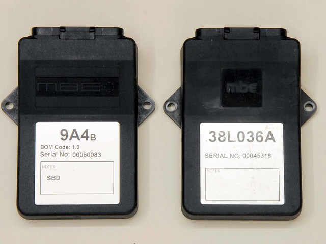
The Caterham R400 map is locked, but I also wanted to keep the original ECU as, one day, I will return the car to it's original spec. So Sb developments have supplied a new 9A4 with a base map for my spec. In order to reduce the inevitable trouble shooting on the new engine, I decided to fit the new ECU to the existing R400 installation before I remove it. It started on the button and ran like a dream - albeit a bit rich.
Before torquing down the head I did one last check that the timing peg I made was accurate. This time I used a dial gauge to measure an arbitrary figure each side of TDC. By reading off the degrees on the timing disc, and splitting the difference, I was able to locate TDC. This matched the peg with no measurable error. Time to move on
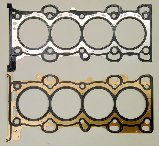
I think most people use an OME type gasket and I decided to purchased the Cosworth item, which appearers to be identical to all the other sources I've seen. It is, however, not identical to the standard FoMoCo item in that the water gallery holes are more restricted - particularly on the exhaust side. But it does have additional holes at the front. I'm guessing that this is a result of some development work to better balance the flow of coolant in the head.
This was a significant day in the project today - the old engine came out. No going back now
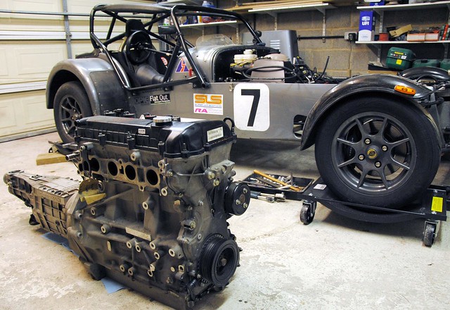
The 'old' engine is now in the process of being stripped of components need for the 'new engine'. A bit I always liked is this breather cover. The dry sump will do away with the breather so this little cover supplied by Caterham does a nice job of covering up the hole. Not a budget item though!
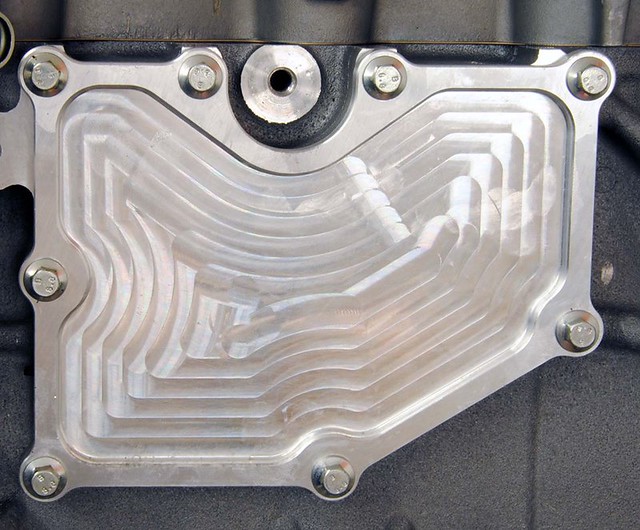
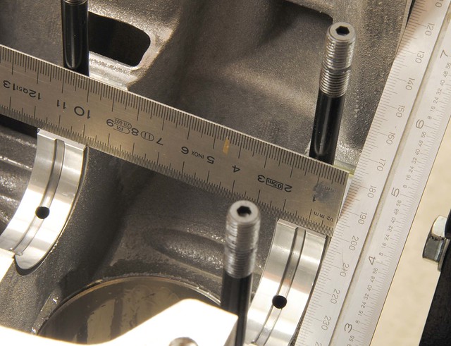
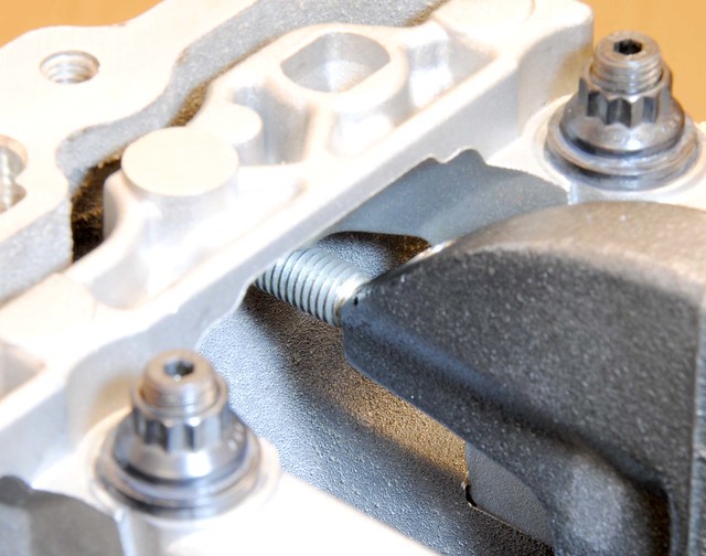
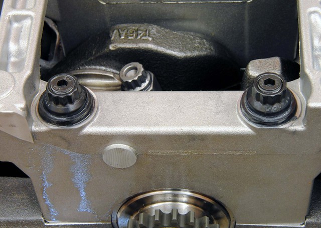
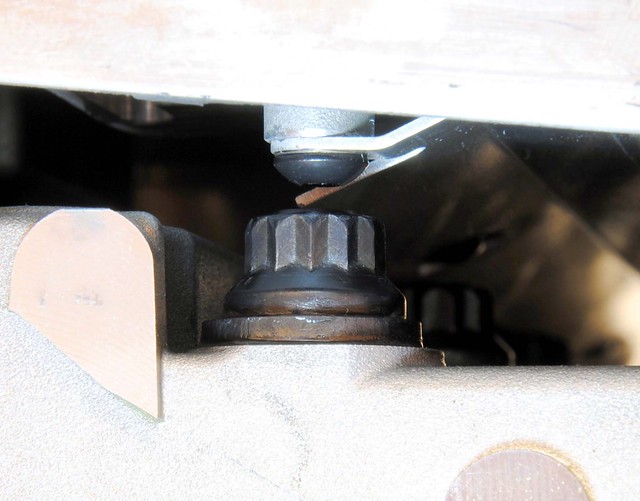
The first major setback looms on the horizon . In fairness, Mic had tipped me off that the sump may not clear the the ARP main studs and, and when stripping the Titan sump off the old engine, it became clear that this sump may have this problem. You can see how close the standard bolts are in the picture. and the ARP studs were about 1 cm longer. The options may be to shorten the studs, or return to the standard bolts. Some careful measurements need to be made . . .
The ARP stud problem: If you look for it, there's quite a lot on the forums about this. Basically the studs appear to be too long and hit the wndage tray. I found it hard to believe that a company like ARP would manufacture a part that would not fit, so first step was to check how deep the threaded hole was in the block. Lo and behold, it was about a 1 mm longer than required.
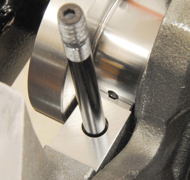
Next step was to look closely at the stud and look for witness marks where the thread may be binding. Sure enough, the top of the thread looked like it was beginning to get tight. This was good news as, if it had been at the bottom, then the thread would not have been long enough. I needed three more threads and was confident that they could be tightened by this much. It didn't take much torque to tighten them fully home and I probably would have done this if the instruction had not said 'finger tight'. Problem solved
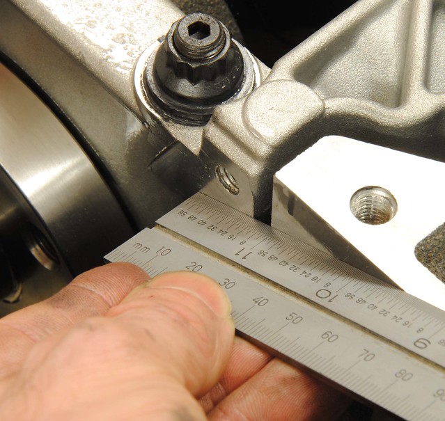
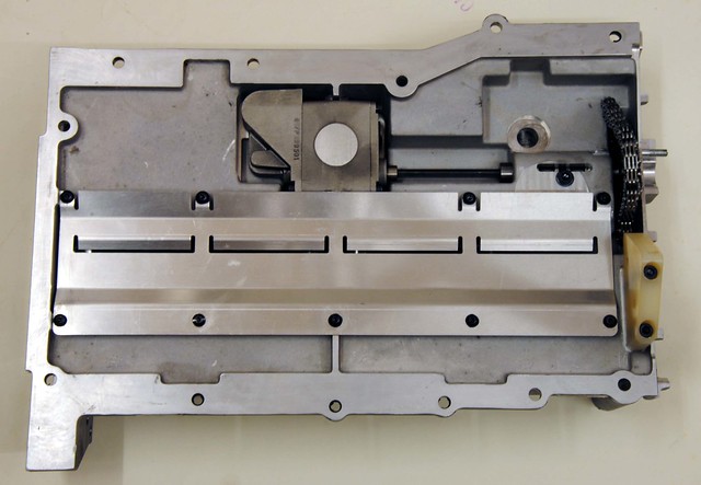
Here’s the sump ‘trial’ fitted to check clearance. In the end there was more than I expected.
I'm continuing to clean up the components from the old engine and hope to move on assembling them on the new engine soon
Daily post here https://www.facebook.com/Duratec.in.detail
Before torquing down the head I did one last check that the timing peg I made was accurate. This time I used a dial gauge to measure an arbitrary figure each side of TDC. By reading off the degrees on the timing disc, and splitting the difference, I was able to locate TDC. This matched the peg with no measurable error. Time to move on
I think most people use an OME type gasket and I decided to purchased the Cosworth item, which appearers to be identical to all the other sources I've seen. It is, however, not identical to the standard FoMoCo item in that the water gallery holes are more restricted - particularly on the exhaust side. But it does have additional holes at the front. I'm guessing that this is a result of some development work to better balance the flow of coolant in the head.
This was a significant day in the project today - the old engine came out. No going back now
The 'old' engine is now in the process of being stripped of components need for the 'new engine'. A bit I always liked is this breather cover. The dry sump will do away with the breather so this little cover supplied by Caterham does a nice job of covering up the hole. Not a budget item though!
The first major setback looms on the horizon . In fairness, Mic had tipped me off that the sump may not clear the the ARP main studs and, and when stripping the Titan sump off the old engine, it became clear that this sump may have this problem. You can see how close the standard bolts are in the picture. and the ARP studs were about 1 cm longer. The options may be to shorten the studs, or return to the standard bolts. Some careful measurements need to be made . . .
The ARP stud problem: If you look for it, there's quite a lot on the forums about this. Basically the studs appear to be too long and hit the wndage tray. I found it hard to believe that a company like ARP would manufacture a part that would not fit, so first step was to check how deep the threaded hole was in the block. Lo and behold, it was about a 1 mm longer than required.
Next step was to look closely at the stud and look for witness marks where the thread may be binding. Sure enough, the top of the thread looked like it was beginning to get tight. This was good news as, if it had been at the bottom, then the thread would not have been long enough. I needed three more threads and was confident that they could be tightened by this much. It didn't take much torque to tighten them fully home and I probably would have done this if the instruction had not said 'finger tight'. Problem solved
Here’s the sump ‘trial’ fitted to check clearance. In the end there was more than I expected.
I'm continuing to clean up the components from the old engine and hope to move on assembling them on the new engine soon
Daily post here https://www.facebook.com/Duratec.in.detail
Edited by DCL on Sunday 9th February 23:02
time for an update!
I am using a Caterham branded Titan sump that I purchased in my 2010 upgrade. I covered it on a previous blog so won't go into detail here. It pre-dates the Raceline sump that most people use today and does not provide ground clearance of that unit, but otherwise works well. But there is a weakness in the connection to the pump which needs to be checked: a 'top hat' arrangement provides 2 O-rings that are squashed between the sump but the pump. If the oil pump is ever removed, you need torque it up while it is held up towards the the sump to guarantee a good position and seal.
The cams are Ultimate Performance's UL39 & UL40. The choice was made purely on Simon's recommendation for the spec I wanted.
With the initial timing set using the slots on the cams at TDC (Simon felt this was the best way to start), I checked the valve timing with a dial gauge. If you have ever done this you'll understand how difficult it is to get your head round the readings. But after checking a few text books, it began to make sense - they are around 60 80 80 50, with duration of 320 (inlet) and 310 (exhaust). The textbooks suggest this will give a useful RPM range of 3500 - 9000 with peak power somewhere around 8500. Somewhat wilder than I expected but we'll see how it goes .
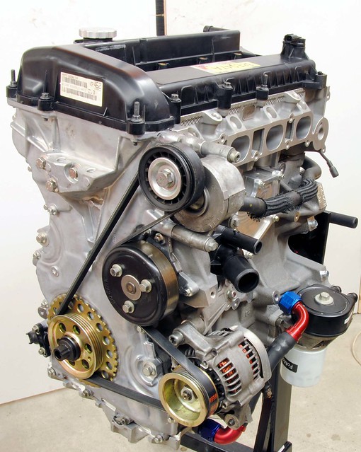
With the engine sealed up I began fitting the auxiliaries. I had thought about fitting the alternator on the exhaust side but, as the smaller pulley worked fine with the original set-up, I decided to keep it that way. Next will be the roller barrels overhaul and fitting.
As planned the barrels were overhauled and fitted today. I was surprised at how poor the condition was that they were in, mainly with wear and corrosion. They've done about 5K miles - and they will certainly be past their best by 10K.
They are, however, a very simple device once the end plates are removed and it was not long before they were done and fitted to the engine. But I did make the classic mistake of not removing the TPS first, so now it's scrap .
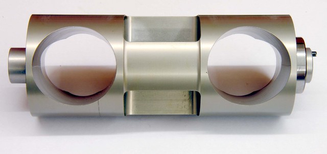
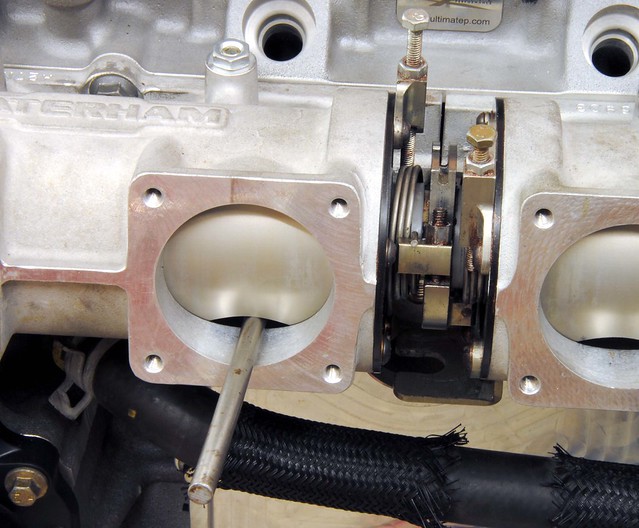
Setting them up is not difficult. Using a 6mm rod to hold them open, the end stops are adjusted in turn to take up the slack. It is worth saying that the 6mm gap at the front is not the 'throttle' opening - that all happens at the back (engine) side. This procedure effectively set the barrel to 'just' closed. There is also a bleed hole which will be adjusted to get idle flow correct when I'm up and running.
Well, the engine is now finished . the final touch was to fit the rather nice flywheel and twin plate Super Clutch from SB Developments.
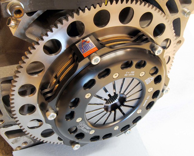
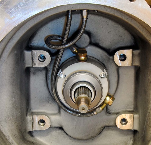
The twin plate super clutch is thicker and needs a rounded clutch release bearing. This was supplied with a new release mechanism by SB developments as part of the clutch kit. It also has a spacer to provide the correct position. The hardest part was making up the hoses.
The engine went in today - a fairly standard job with no real issues but the clutch does feel rather 'firm'. I'm sure I'll get used to it. All the fluids are in but the TPS didn't arrive, so couldn't start it up - maybe Monday
The big moment came! With my son supervising me (and keeping me right) the start button was pushed. I was surprised that it fired instantly. Although I stopped the video by accident, I continued to run it for about 20 minutes. I will not run again until it is on the rolling road next week - so that it's run-in under load.
http://www.youtube.com/watch?v=hrksbKEXfFI
I am using a Caterham branded Titan sump that I purchased in my 2010 upgrade. I covered it on a previous blog so won't go into detail here. It pre-dates the Raceline sump that most people use today and does not provide ground clearance of that unit, but otherwise works well. But there is a weakness in the connection to the pump which needs to be checked: a 'top hat' arrangement provides 2 O-rings that are squashed between the sump but the pump. If the oil pump is ever removed, you need torque it up while it is held up towards the the sump to guarantee a good position and seal.
The cams are Ultimate Performance's UL39 & UL40. The choice was made purely on Simon's recommendation for the spec I wanted.
With the initial timing set using the slots on the cams at TDC (Simon felt this was the best way to start), I checked the valve timing with a dial gauge. If you have ever done this you'll understand how difficult it is to get your head round the readings. But after checking a few text books, it began to make sense - they are around 60 80 80 50, with duration of 320 (inlet) and 310 (exhaust). The textbooks suggest this will give a useful RPM range of 3500 - 9000 with peak power somewhere around 8500. Somewhat wilder than I expected but we'll see how it goes .
With the engine sealed up I began fitting the auxiliaries. I had thought about fitting the alternator on the exhaust side but, as the smaller pulley worked fine with the original set-up, I decided to keep it that way. Next will be the roller barrels overhaul and fitting.
As planned the barrels were overhauled and fitted today. I was surprised at how poor the condition was that they were in, mainly with wear and corrosion. They've done about 5K miles - and they will certainly be past their best by 10K.
They are, however, a very simple device once the end plates are removed and it was not long before they were done and fitted to the engine. But I did make the classic mistake of not removing the TPS first, so now it's scrap .
Setting them up is not difficult. Using a 6mm rod to hold them open, the end stops are adjusted in turn to take up the slack. It is worth saying that the 6mm gap at the front is not the 'throttle' opening - that all happens at the back (engine) side. This procedure effectively set the barrel to 'just' closed. There is also a bleed hole which will be adjusted to get idle flow correct when I'm up and running.
Well, the engine is now finished . the final touch was to fit the rather nice flywheel and twin plate Super Clutch from SB Developments.
The twin plate super clutch is thicker and needs a rounded clutch release bearing. This was supplied with a new release mechanism by SB developments as part of the clutch kit. It also has a spacer to provide the correct position. The hardest part was making up the hoses.
The engine went in today - a fairly standard job with no real issues but the clutch does feel rather 'firm'. I'm sure I'll get used to it. All the fluids are in but the TPS didn't arrive, so couldn't start it up - maybe Monday
The big moment came! With my son supervising me (and keeping me right) the start button was pushed. I was surprised that it fired instantly. Although I stopped the video by accident, I continued to run it for about 20 minutes. I will not run again until it is on the rolling road next week - so that it's run-in under load.
http://www.youtube.com/watch?v=hrksbKEXfFI
Gassing Station | Caterham | Top of Page | What's New | My Stuff