To D2HTB or RBTB, that is the question.
Discussion


I'm going to be purchasing some throttle bodies for my 1800 Caterham and can't decide to go with either the Jenvey DTH offering, or the Titan Roller Barrel setup like the R400 etc. I'd like to keep it looking like the std Caterham cars, and the cost difference is minimal.
What are you thoughts?
P.
What are you thoughts?
P.
It already runs Alpha-N, the two factors that impair drivability and smooth progression are the volume of air between the throttle plate/bar and the inlet valves which is much higher with the RTBS and the tortuous route through the TB at partial throttle which prevent a smooth annulus of air around the port until full throttle
Oily
Oily
DVandrews said:
It already runs Alpha-N, the two factors that impair drivability and smooth progression are the volume of air between the throttle plate/bar and the inlet valves which is much higher with the RTBS and the tortuous route through the TB at partial throttle which prevent a smooth annulus of air around the port until full throttle
Oily
and you don't want anything preventing a smooth annulus Oily

Sorry, deeply unprofessional but I couldn't resist....

DVandrews said:
I figured that might cause a chortle.. But it stands true regardless.
Dave
Sorry, purile I know!Dave
So this has however made me think I should check the idle flow rates on my R400.
Would I be right in thinking its a case of ballancing the flow rates through the pairs of RBs, then setting the TPS with a multimeter?
bertie said:
Sorry, purile I know!
So this has however made me think I should check the idle flow rates on my R400.
Would I be right in thinking its a case of ballancing the flow rates through the pairs of RBs, then setting the TPS with a multimeter?
Spot on, if you have an imbalance between cylinders on the same TB then I would give the engine a hot compression test, if this is OK then the problem will lie with the TBs and only some hairy modifications will correct itSo this has however made me think I should check the idle flow rates on my R400.
Would I be right in thinking its a case of ballancing the flow rates through the pairs of RBs, then setting the TPS with a multimeter?
Dave
DVandrews said:
Spot on, if you have an imbalance between cylinders on the same TB then I would give the engine a hot compression test, if this is OK then the problem will lie with the TBs and only some hairy modifications will correct it
Dave
Great, what voltage am I looking for with no throttle on the TPS?Dave
Presumably the ECU derives a stable referance voltage output to the TPS so battery voltage is irrelevant?
Mines a 2003 R400 K series which you fitted verniers to for me

bertie said:
Great, what voltage am I looking for with no throttle on the TPS?
Presumably the ECU derives a stable referance voltage output to the TPS so battery voltage is irrelevant?
Mines a 2003 R400 K series which you fitted verniers to for me
You will be measuring resistance, not voltage and it should be 0.43OHMs or thereabouts between pins 1 & 2 as viewed from the front of the TPS. The TPS is measured when the connector is off so it can't generate any voltage.....Presumably the ECU derives a stable referance voltage output to the TPS so battery voltage is irrelevant?
Mines a 2003 R400 K series which you fitted verniers to for me
Dave
[
Edited by DVandrews on Tuesday 2nd September 16:02
DVandrews said:
You will be measuring resistance, not voltage and it should be 0.43OHMs or thereabouts between pins 1 & 2 as viewed from the front of the TPS. The TPS is measured when the connector is off so it can't generate any voltage.....
Dave
[
Great, thanks, thats my Saturday morning sorted :thumbsup:Dave
[
Edited by DVandrews on Tuesday 2nd September 16:02
I had assumed the ECU gave out a referance voltage so I was going to piggyback a probe with the ignition on.
Resistence is much easier!
I'm going to have to step in here.
I've never measured resistance stting up throttle bodies on an MBE ECU. The throttle pot input is an analogue voltage output between 0 and 5 volts. Were resistance the metric by which the ECU derives throttle position surley the throttle pot would only require two connections.
That aside the TPS is a 5k logarithmic pot, do 0.43ohms would be impossible to set.
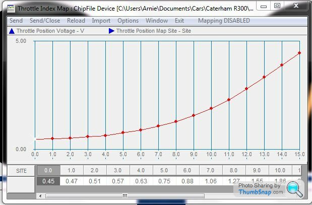
As the maps can vary - in this case the throttle index map - you need to set the idle position to the voltage. On most MBE maps out of Caterham load site 0 is at 0.45v. You do need to make sure it is bang on .45 - i.e not .44 or .46. You also need to check you have the correct airflow through the bodies when setting this. Between 5 and 6 kg/hr is correct.
I've never measured resistance stting up throttle bodies on an MBE ECU. The throttle pot input is an analogue voltage output between 0 and 5 volts. Were resistance the metric by which the ECU derives throttle position surley the throttle pot would only require two connections.
That aside the TPS is a 5k logarithmic pot, do 0.43ohms would be impossible to set.
As the maps can vary - in this case the throttle index map - you need to set the idle position to the voltage. On most MBE maps out of Caterham load site 0 is at 0.45v. You do need to make sure it is bang on .45 - i.e not .44 or .46. You also need to check you have the correct airflow through the bodies when setting this. Between 5 and 6 kg/hr is correct.
According to the official guide to installation of the throttle bodies, the pot should be set to read 0.45Ohms between pins 1&2.
There is no mention of voltage and with the plug off I don't see how any voltage could be generated.
I have set up around 60 sets using this guide as issued by Caterham/Minister some time ago.
Since I have personally measured and set the resistance around 60 times then I must disagree with yoru assertions.
If I had access to the web from my main Data PC I would post the guide here. Unfortunately web access has crashed and I am in the process of reviving it.
Dave
The circuit for thr throttle pot is a potential divider.
5v at one end, 0v at the other.
The track resistance is 5k ohms +/- a percentage tolerance.
It is possible a rudimentary calibration could be achived were you setting the pot at 0.43Kohms - is this what you meant?
its not a 'best practice' though. The map references the TPS in volts, therefore it should be set in volts. A resistance method does not consider the overall tolerence of the TPS, which will effect the output voltage.
Nonetheless, that is the recommendation in the installation guide which Caterham saw fit to publish and distribute. And it is the setting that you said would be Impossible to achieve.
In just about every case of poor idle and progression, balancing the TBs to 5.5KG/hr and then setting the TPS to 0.45ohm resistance has transformed the engines behaviour.
I think I will continue with the recommended method.
Dave
In just about every case of poor idle and progression, balancing the TBs to 5.5KG/hr and then setting the TPS to 0.45ohm resistance has transformed the engines behaviour.
I think I will continue with the recommended method.
Dave
Dave, i'm not going to argue with you on the vast majority of what you post as you will almost always be correct. This specific subject matter however is something I am well qualified in.
Firstly if the instructions state 0.45ohm that is a laugable error. Knowing they come from Caterham however means its entirley possible. It must be 0.45Kohm. This is for reasons I shall explain later.
Caterham have often come up with non-scientific bodged solutions. This is clearly one of them. They don't want their customers and service engineers requiring Easymap to set up their cars, as it moves these people out of their competence zone and to a place where they can do lots of damage.
Setting the throttle pot by resistance is akin to setting your tracking by eye.
The method will introduce issues into the running of the car if it is not mapped to mildly overfuel. This is because not all 5kohm variable resistors are exactly 5kohms. There can be an up to 10% varience. Setting by voltage overcomes this, setting by resistence does not.
So lets agree a few things:
First, lets agree the throttle ondex map is calibrated in Volts not Ohms. See the V in the top left on this map:
Now lets look at how the TPS works:
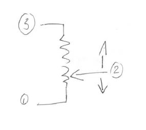
The numbers represent the pins. 1 is 0v (electronics ground on the ECU) 2 is the output from the TPS. The voltage from this increases as the throttle is pressed, incrementing the fueling and ignition through their respective maps. Pin 3 is the critical one. It has 5v TTL level on it. This means it is exactly 5v so long as the current draw is correct. With the TPS having a resistence of circa 5000 ohms, the current draw is correct at around 1ma.
So were the resistance of the TPS exactly 5k ohms and the resistance across pins 1 and 2 set to 0.45 kohms, you would see an output of 0.45volts. Sadly the resistance of the TPS is never exactly 5k ohms and can vary by as much as 10%. Your 4.5Kohms will then output between 0.40 and 0.45v.
If you go back to the throttle index map above it puts you between load site 1 and 2 at the upper extreme, whihc means you over fuel (rough idle etc) or the inverse is that there is latency in how applying throttle moves up the throttle and ignition maps - it runs lean and over advanced. If the engine is accurately mapped this could result in a failure.
Caterham's standard maps on the K are always overfueled so this is unlikely to be a problem. But if your engine is remapped to be much tighter on stoichiometric combustion and then you decide to recal the TPS using the resistance method, there is a very big risk.
Firstly if the instructions state 0.45ohm that is a laugable error. Knowing they come from Caterham however means its entirley possible. It must be 0.45Kohm. This is for reasons I shall explain later.
Caterham have often come up with non-scientific bodged solutions. This is clearly one of them. They don't want their customers and service engineers requiring Easymap to set up their cars, as it moves these people out of their competence zone and to a place where they can do lots of damage.
Setting the throttle pot by resistance is akin to setting your tracking by eye.
The method will introduce issues into the running of the car if it is not mapped to mildly overfuel. This is because not all 5kohm variable resistors are exactly 5kohms. There can be an up to 10% varience. Setting by voltage overcomes this, setting by resistence does not.
So lets agree a few things:
First, lets agree the throttle ondex map is calibrated in Volts not Ohms. See the V in the top left on this map:
Now lets look at how the TPS works:
The numbers represent the pins. 1 is 0v (electronics ground on the ECU) 2 is the output from the TPS. The voltage from this increases as the throttle is pressed, incrementing the fueling and ignition through their respective maps. Pin 3 is the critical one. It has 5v TTL level on it. This means it is exactly 5v so long as the current draw is correct. With the TPS having a resistence of circa 5000 ohms, the current draw is correct at around 1ma.
So were the resistance of the TPS exactly 5k ohms and the resistance across pins 1 and 2 set to 0.45 kohms, you would see an output of 0.45volts. Sadly the resistance of the TPS is never exactly 5k ohms and can vary by as much as 10%. Your 4.5Kohms will then output between 0.40 and 0.45v.
If you go back to the throttle index map above it puts you between load site 1 and 2 at the upper extreme, whihc means you over fuel (rough idle etc) or the inverse is that there is latency in how applying throttle moves up the throttle and ignition maps - it runs lean and over advanced. If the engine is accurately mapped this could result in a failure.
Caterham's standard maps on the K are always overfueled so this is unlikely to be a problem. But if your engine is remapped to be much tighter on stoichiometric combustion and then you decide to recal the TPS using the resistance method, there is a very big risk.
A potentiometer is a variable resistor. In this instance it is designed to give a variable voltage according to rotational (throttle) position.
If the map in the ECU has it origin calibrated to an initial TPS position of 0.45Kohms then returning it to this value will simply put it where it is supposed to be.
Dave
If the map in the ECU has it origin calibrated to an initial TPS position of 0.45Kohms then returning it to this value will simply put it where it is supposed to be.
Dave
Edited by DVandrews on Saturday 6th September 10:13
Gassing Station | Caterham | Top of Page | What's New | My Stuff