On the Scrounge
Discussion


With the cooling system all sorted and a thermostat in place for the first time in 25 years finally getting round to a job I've been meaning to do for a long time.
I plan to use the redundant driving lights switch in the panel as a manual cooling fan switch. Aiming to use the switch as a manual override and the indicator powered from the fan supply so I can also see when the otter has kicked in.
As someone has already pinched the wiring for something else, What I am looking for is one of the plastic connector housings that plug on the back of the switches with a couple of connections in place (or even some of the pins which go in the block)
Anybody have anything in their scrap/spares pile?
Mike,
thanks for trying to assist.
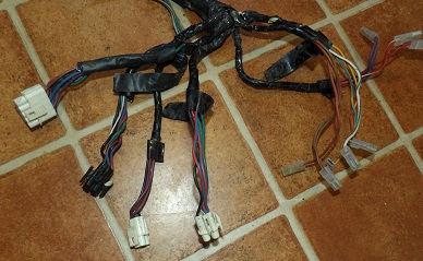
Looking at that there's nothing that looks like it would mate (but hard to tell for certain as i'm not with the car at the minute.)
I've a feeling the spade connectors to the right side of your photo maybe where the switches connect - although I'm working from memory the light switch I am trying to use had blue/white connections. did the rotary types have normal spades?
thanks for trying to assist.
Looking at that there's nothing that looks like it would mate (but hard to tell for certain as i'm not with the car at the minute.)
I've a feeling the spade connectors to the right side of your photo maybe where the switches connect - although I'm working from memory the light switch I am trying to use had blue/white connections. did the rotary types have normal spades?
If you do track some down I'm after one to repair my heater fan switch as mine decided it'd rather be a melty lump of burned plastic.
I couldn't find the connector housing anywhere at all but the pins are the same as used in the TTS connectors that are all over the car I think. I scrounged a couple of spares from changing the throttle pot connector (v8 uses a lucas e series connector on the throttle pot and gearbox speed sensor)
I ought to finish putting my 3d printer together and see if I can make some, how hard can it be?
On the ones I've seen, the otter switch is grounded on one side and the fan motor is also grounded on one side. In that case, my suggested way to wire this up is to take a wire from the fan positive up to the warning lamp and ground the other side of the lamp - this way the lamp lights if the fan is getting power, so it proves the relay, fuses etc are all good. There are other arrangements which light the lamp correctly when everything is working but also light it when a fault is preventing power from reaching the fan. With this setup the lamp may also glow slightly when the fan windmills at high speed - personally I don't see that as a problem.
For the override switch take a wire from otter switch positive up to the override switch and ground the other side of the switch.
This arrangement only needs two wires to be run from the otter switch and fan into the cabin. I run them along the top chassis rail and through a gromit in front of the driver.
If you want to keep it all inside the cockpit you can set up a similar same circuit by running the two wires over the tunnel into the fuse box andconnecting into the fan relay socket, but that way you don't know that power is actually reaching the fan.
GreenV8S said:
If you want to keep it all inside the cockpit you can set up a similar same circuit by running the two wires over the tunnel into the fuse box andconnecting into the fan relay socket, but that way you don't know that power is actually reaching the fan.
This. I will replace the connector to the fan at the same time so indication from the live output of the relay will be fine..Indication will be from the existing lamp in the switch, so no led and keep everything stock.
Edited by RayTVR on Tuesday 26th April 17:15
Gassing Station | S Series | Top of Page | What's New | My Stuff