New 350i owner
Discussion


Elmwood TVR sound like a decent bunch, I have spoken to them in the past..They are also fairly reasonable in terms of price..Dan taylor TVR is also good and doesnt over charge despite some critisism..I hope you can get it sorted soon mate..Good luck..Got my fingers crossed for you..Ziga
Going back to your post on page 2 of this thread
It's also further confusing because you have mis-identified one of the components in your reported symptoms, which make it very difficult for you to apply any suggested solutions if your grasp of component layout/description is dodgy.
For example
You also mentioned ignition timing problems and a hole in the exhaust system, both of which are very difficult for an Efi system to cope with.
In addition, because of possible prior neglect, the chances of there being air leaks into the plenum chamber or other parts of the inlet manifold system are quite high, and this includes rocker cover gaskets, inlet manifold gaskets, brake servo, breather system, main air inlet tube as well as the usual suspects of plenum hoses, etc.
And finally, for you to tackle any actual Efi problems in a meaningful way does require a minimum level of understanding where all the components are located and how the system is supposed to work. Sadly the chances of finding a local professional outfit who can undertake such work are very poor without it costing you an absolute fortune.
Based upon a review of all the pages on this thread and the reported symptoms on this car, my feeing is that you are NOT chasing a single fault, therefor analysing what the symptoms mean is very difficult indeed.
For example if you have a rich mixture due to an over-fuelling fault and at the same time, an uncontrollable weak mixture due to a rogue air leak, finding the cause is gonna be almost down to luck.
Given these observations, I would recommend a meaningful plan.
1 obtain a copy of an Efi ops manual
2 study it in depth to grasp how the system is supposed to work.
3 review the available in-depth archives of flapper component locations and descriptions
4 apply a simple and economic health check for the Efi system and follow up every suggestion there-in.
The latter can be found Here
ralph350i said:
I decided to sort the wiring, what a mess, no wonder the car dont run, most if all the connectors where loose or broken, earth straps where corroded to fook, wires hanging off and most, if not all, the vacuum pipes from the EFI were loose, clips not done up and wires which were just cut and left with no insulation, so after 4 cold hours all the above is now sorted, dizzy leads run correctly, all electric plugs wd40 and engine bay has been part cleaned
then reviewing the various symptoms which suggest the car is seriously over-fuelling, I think you still have problems with the integrity of your Efi wiring loom.It's also further confusing because you have mis-identified one of the components in your reported symptoms, which make it very difficult for you to apply any suggested solutions if your grasp of component layout/description is dodgy.
For example
ralph350i said:
i did install a new coolant temp switch, but the car will still not run with it connected???? so am having to link the connector to by pass the switch and tell the ecu not to over fuel
Then later it seems clear that there must still be a wiring loom problem thereabouts -ralph350i said:
the strange thing is the car will not even start if i connect the new coolant temp switch, so have to have it disconnected with a link?? Car then starts fine when hot or cold but is missing underload
Furthermore, you also reported that the car/engine may have been in poor condition when purchased, and if so, then getting thro' to all the potentially faulty Efi conditions should be tackled with some sort of plan. Randomly addressing various components and even replacing them just based upon forum suggestions will not achieve anything other than costing loadsa money.You also mentioned ignition timing problems and a hole in the exhaust system, both of which are very difficult for an Efi system to cope with.
In addition, because of possible prior neglect, the chances of there being air leaks into the plenum chamber or other parts of the inlet manifold system are quite high, and this includes rocker cover gaskets, inlet manifold gaskets, brake servo, breather system, main air inlet tube as well as the usual suspects of plenum hoses, etc.
And finally, for you to tackle any actual Efi problems in a meaningful way does require a minimum level of understanding where all the components are located and how the system is supposed to work. Sadly the chances of finding a local professional outfit who can undertake such work are very poor without it costing you an absolute fortune.
Based upon a review of all the pages on this thread and the reported symptoms on this car, my feeing is that you are NOT chasing a single fault, therefor analysing what the symptoms mean is very difficult indeed.
For example if you have a rich mixture due to an over-fuelling fault and at the same time, an uncontrollable weak mixture due to a rogue air leak, finding the cause is gonna be almost down to luck.
Given these observations, I would recommend a meaningful plan.
1 obtain a copy of an Efi ops manual
2 study it in depth to grasp how the system is supposed to work.
3 review the available in-depth archives of flapper component locations and descriptions
4 apply a simple and economic health check for the Efi system and follow up every suggestion there-in.
The latter can be found Here
Many Thanks for the replies Guys there much appriceiated.
In regards to the efi i may have not been fully clear about further developements i found yesterday,. so after running the car, i removed the spark plugs only to find that the tips where white which would indicate air leaking into inlet system. suspect Air Valve or one of many vacuum connections, Ian did indicate that the AFM had been adjusted so am betting that the mixture has been weaken of way to far ( how do i adjust please is it the alan key at the side of the unit??) and after removing the NGK plugs i fitted some champion items with a longer tip which cured the lumpy idle, the car run alot better but still sounded like air was leaking into the system, in regards to the CTP, surely if a link is place and the car then starts this would indicate that the wires are in working order telling the ECU not to overfuel?????
So know my main concern now is the noise which appears to come from the sump area which is quite loud, its hard to describe but i,ll post a video of the noise later today to see if that helps, my one question would be if its not a big end noise ( which it defo is not) then what could cause a bottom end inconsistent knocking/rattling sound, oil pump?? spun bearing shells? sorry for all the questions but am hoping you guys could give me a understand off what could be the issue could be.
Kind Regards
Ralph
Hi Mate..I think that a video of the sound of this rattle would help..It could be an Exhaust bracket/flange..Heat sheild..Cat falling apart inside..(If fitted)..Pulley..oil pump..Belt tensioner..Gearbox or the teeth on the ring gear are damaged and hitting the gear teeth on the starter..You did have starter issues that could of caused damage..I hope its nothing too serious mate and you can soon enjoy the wedge..Cheers..Ziga
ralph350i said:
i removed the spark plugs only to find that the tips where white which would indicate air leaking into inlet system. suspect Air Valve or one of many vacuum connections
So, it is very likely you have to perform the dynamic investigation for rogue air leaks as indicated in #12 of my 15 point health check.ralph350i said:
Ian did indicate that the AFM had been adjusted so am betting that the mixture has been weakened off way to far (how do i adjust please is it the alan key at the side of the unit??)
The allen key only adjusts CO mixture at idle. As for readjusting the AFM innards for mixture change across the whole rpm range, it is not for the faint hearted, but given a reasonable study and the right circumstances plus some CO measuring equipment it is do-able. This would be an ideal time to follow up by reading the link from #9 of the same health check,(everything you could possibly need to know about the AFM) to decide if and how to perform that somewhat complex procedure.
There is also an empirical process suggested that would depend only on observing spark plug colour.
honestjohntoo said:
The allen key only adjusts CO mixture at idle. As for readjusting the AFM innards for mixture change across the whole rpm range, it is not for the faint hearted, but given a reasonable study and the right circumstances plus some CO measuring equipment it is do-able.
This would be an ideal time to follow up by reading the link from #9 of the same health check,(everything you could possibly need to know about the AFM) to decide if and how to perform that somewhat complex procedure.
There is also an empirical process suggested that would depend only on observing spark plug colour.
Hi Honest-johntooThis would be an ideal time to follow up by reading the link from #9 of the same health check,(everything you could possibly need to know about the AFM) to decide if and how to perform that somewhat complex procedure.
There is also an empirical process suggested that would depend only on observing spark plug colour.
i have been though the hole PDF and carried out all the electrical test and the reading all stack up to be correct, this inculdes ecu, afm, injectors, wiring you name it i have completed it, so that really leaves me with mixture setting, timing and the coolant temp switch which for the life of me i dont understand, as surely if the link is place and the car then starts surely the ecu is picking up the signal and doing its job?? where it not making any difference i would defo be looking further into the wiring.
Hi Adam
i have check and cleaned every earth and been though the wiring on the car and all is in the correct order and in fairness to Ian i understand why he was scratching his head as his mechinic had the timing out 180 degs and this CTS is not only confusing me it must have driven him mad.
Hi Ziga
Thanks mate, hopefully the vids may help, i did speak to a guy today who am told knows his way around a Rover engine and hopefully he will come and have a look.
Hi Mike
Many thanks mate am sure i,ll get there one day lol
Well here's 2 video's i took yesterday of the noise, the first one starts from the engine bay then when the video goes black my iphone is postioned in the driver side wheel well, the 2nd is in the wheel well again, there not great but it may help hopefully, i,ll do another with the drive belts removed just to see if that make any difference, many thanks.

ralph350i said:
the coolant temp switch which for the life of me i dont understand, as surely if the link is place and the car then starts surely the ecu is picking up the signal and doing its job?? where it not making any difference i would defo be looking further into the wiring.
I really have no idea what link you are talking about and what it does. Is it possible you are describing a resistor used as a "get U home dodge".Either way, in the meantime all I can suggest is more study for you to test the sensor and all its connections..
Coolant Temperature Sensor
Location and Operation
The Rover SD1 Efi Coolant Temperature Sensor (CTS) is located in the coolant gallery at front left of the inlet manifold alongside but slightly behind the thermo-time switch. It informs the ECU of engine temperature changes so it can compute injector "open time" to provide correct fuel / air mixture for any temperature condition. eg: From cold, the CTS resistance falls continuously according to the profile below until the engine temperature stabilises. Thereafter minor changes are monitored accordingly.
Failure Modes
The CTS is a key component of the Rover SD1 Efi System and, in truth, in conjunction with its wiring and connector, not very reliable. Recent anecdotal evidence indicates a fairly high fail rate which has a serious effect on the operation of the system. eg: The CTS and/or its wiring can go open circuit, falsely signalling the ECU that the engine remains cold, which in turn computes a rich air / fuel mixture resulting in significant overfuelling. At best, this produces very lumpy performance and at worst, floods the engine such that it will not start or run. Fortunately it is easy to test.
Circuit
The CTS has a silicon element that changes its resistance to signal a change of temperature so the ECU can compute injector "open time"
It is connected to pin 13 and earth pins 5,16,17 and 35 of the ECU. The the other (very important) earth on the black/white (BW) wire is a heavy duty ring tag on the Efi loom going to an earth stud on the engine block behind and below the LH rocker cover

Testing
Conditions as follows: Engine HOT, ECU multiplug disconnected as in A: Ignition OFF: Measure coolant temperature with thermal probe: Connect an ohmmeter as shown in B below and take a single reading. Compare it to the resistance/temperature profile below. Consider connecting the ohmmeter for only short periods, not in fear of damage, but the meter battery may cause the sensor to heat up and give an incorrect reading. Allow the engine to cool and take further readings. If the measurements match the profile within (say) 10-15%, the CTS and its connections are OK.

TEMP.......OHMS........TEMP........OHMS
-10°C...9100-9300....60°C.......500-700
0°C.......5700-5900....80°C.......300-400
20°C.....2400-2600....100°C....150-200
40°C.....1100-1300
If the readings are clearly wrong, remove the sensor for a controlled test using a pan of water and thermometer.
Suspend the sensor in the water and bring to the boil. Compare resistance readings to the profile. Variations of (say) 10 -15% are not critical but if they are obviously way off or there is a clear intermittant or distorted result then consider the test failed. Obtain a replacement unit, check it as above to verify OK, fit it into the manifold and reconnect to the Efi circuit. Reconnect the ohmmeter as in B and repeat the measurement between the ECU pin 13 and earth. If this still incorrect there is a wiring problem so check the black/slate wire (BS) and black/white wire (BW) and their connections paying particular attention to the earth stud at the rear of the engine.
Temporary Get U Going Trick
Study of the chart shows at optimum coolant temperature of 90 deg C, the resistance of the CTS would be in the order of 200 ohms thus revealing a workable temporary solution to a faulty sensor.
When cold, start the engine with the sensor plug disconnected to get benefit from cold start enrichment. When the engine warms up and falters, insert a 200 ohm resistor into the sensor plug allowing normal driving to continue as long as the engine remains warm/hot. If difficult to restart when warm, a bootful of the accelerator pedal will enrichen the mixture sufficiently to get moving again; and of course when the engine is cold, remove the temporary resistor from the sensor plug.
A practical trick highly dependent upon sufficient foresight to obtain a 200 ohm resistor. The really elegant solution is to keep a resistor taped to the sensor cable in anticipation!
Conclusions
The components in the Rover SD1 Efi System have varying degrees of reliability but generally they are quite robust. The lifetime of the CTS is thought to be between 100k and 200k miles, however, problems with this component often manifest themselves much sooner due to wiring or connector problems. The under-bonnet environment for an Efi Engine is very hostile due to extremely high temperatures generated by the latent heat of the engine which convects and conducts upwards into the aluminium manifold and plenum chamber. More so, when the car is parked up for short periods in very hot weather. The under-bonnet blanket installed for sound deadening reasons also acts as an efficient insulator trapping the excess heat for long periods. Such hostile temperature changes play havoc with the poorly specified Efi wiring loom and connectors which can become very brittle causing cracking and encouraging corrosion. Consequently, because of its importance to the correct fueling of the engine when problems with the CTS are suspected, the first simple tests to perform would be to check the integrity of its connectors. Failing that, the recommended test procedure will identify any or all of the problems.
Apologies if you have already studied this.
honestjohntoo said:
really have no idea what link you are talking about and what it does. Is it possible you are describing a resistor used as a "get U home dodge".
Either way, in the meantime all I can suggest is more study for you to test the sensor and all its connections..
Coolant Temperature Sensor
Location and Operation
The Rover SD1 Efi Coolant Temperature Sensor (CTS) is located in the coolant gallery at front left of the inlet manifold alongside but slightly behind the thermo-time switch. It informs the ECU of engine temperature changes so it can compute injector "open time" to provide correct fuel / air mixture for any temperature condition. eg: From cold, the CTS resistance falls continuously according to the profile below until the engine temperature stabilises. Thereafter minor changes are monitored accordingly.
Failure Modes
The CTS is a key component of the Rover SD1 Efi System and, in truth, in conjunction with its wiring and connector, not very reliable. Recent anecdotal evidence indicates a fairly high fail rate which has a serious effect on the operation of the system. eg: The CTS and/or its wiring can go open circuit, falsely signalling the ECU that the engine remains cold, which in turn computes a rich air / fuel mixture resulting in significant overfuelling. At best, this produces very lumpy performance and at worst, floods the engine such that it will not start or run. Fortunately it is easy to test.
Circuit
The CTS has a silicon element that changes its resistance to signal a change of temperature so the ECU can compute injector "open time"
It is connected to pin 13 and earth pins 5,16,17 and 35 of the ECU. The the other (very important) earth on the black/white (BW) wire is a heavy duty ring tag on the Efi loom going to an earth stud on the engine block behind and below the LH rocker cover
Testing
Conditions as follows: Engine HOT, ECU multiplug disconnected as in A: Ignition OFF: Measure coolant temperature with thermal probe: Connect an ohmmeter as shown in B below and take a single reading. Compare it to the resistance/temperature profile below. Consider connecting the ohmmeter for only short periods, not in fear of damage, but the meter battery may cause the sensor to heat up and give an incorrect reading. Allow the engine to cool and take further readings. If the measurements match the profile within (say) 10-15%, the CTS and its connections are OK.
TEMP.......OHMS........TEMP........OHMS
-10°C...9100-9300....60°C.......500-700
0°C.......5700-5900....80°C.......300-400
20°C.....2400-2600....100°C....150-200
40°C.....1100-1300
If the readings are clearly wrong, remove the sensor for a controlled test using a pan of water and thermometer.
Suspend the sensor in the water and bring to the boil. Compare resistance readings to the profile. Variations of (say) 10 -15% are not critical but if they are obviously way off or there is a clear intermittant or distorted result then consider the test failed. Obtain a replacement unit, check it as above to verify OK, fit it into the manifold and reconnect to the Efi circuit. Reconnect the ohmmeter as in B and repeat the measurement between the ECU pin 13 and earth. If this still incorrect there is a wiring problem so check the black/slate wire (BS) and black/white wire (BW) and their connections paying particular attention to the earth stud at the rear of the engine.
Temporary Get U Going Trick
Study of the chart shows at optimum coolant temperature of 90 deg C, the resistance of the CTS would be in the order of 200 ohms thus revealing a workable temporary solution to a faulty sensor.
When cold, start the engine with the sensor plug disconnected to get benefit from cold start enrichment. When the engine warms up and falters, insert a 200 ohm resistor into the sensor plug allowing normal driving to continue as long as the engine remains warm/hot. If difficult to restart when warm, a bootful of the accelerator pedal will enrichen the mixture sufficiently to get moving again; and of course when the engine is cold, remove the temporary resistor from the sensor plug.
A practical trick highly dependent upon sufficient foresight to obtain a 200 ohm resistor. The really elegant solution is to keep a resistor taped to the sensor cable in anticipation!
Conclusions
The components in the Rover SD1 Efi System have varying degrees of reliability but generally they are quite robust. The lifetime of the CTS is thought to be between 100k and 200k miles, however, problems with this component often manifest themselves much sooner due to wiring or connector problems. The under-bonnet environment for an Efi Engine is very hostile due to extremely high temperatures generated by the latent heat of the engine which convects and conducts upwards into the aluminium manifold and plenum chamber. More so, when the car is parked up for short periods in very hot weather. The under-bonnet blanket installed for sound deadening reasons also acts as an efficient insulator trapping the excess heat for long periods. Such hostile temperature changes play havoc with the poorly specified Efi wiring loom and connectors which can become very brittle causing cracking and encouraging corrosion. Consequently, because of its importance to the correct fueling of the engine when problems with the CTS are suspected, the first simple tests to perform would be to check the integrity of its connectors. Failing that, the recommended test procedure will identify any or all of the problems.
Apologies if you have already studied this.
Hi JohnEither way, in the meantime all I can suggest is more study for you to test the sensor and all its connections..
Coolant Temperature Sensor
Location and Operation
The Rover SD1 Efi Coolant Temperature Sensor (CTS) is located in the coolant gallery at front left of the inlet manifold alongside but slightly behind the thermo-time switch. It informs the ECU of engine temperature changes so it can compute injector "open time" to provide correct fuel / air mixture for any temperature condition. eg: From cold, the CTS resistance falls continuously according to the profile below until the engine temperature stabilises. Thereafter minor changes are monitored accordingly.
Failure Modes
The CTS is a key component of the Rover SD1 Efi System and, in truth, in conjunction with its wiring and connector, not very reliable. Recent anecdotal evidence indicates a fairly high fail rate which has a serious effect on the operation of the system. eg: The CTS and/or its wiring can go open circuit, falsely signalling the ECU that the engine remains cold, which in turn computes a rich air / fuel mixture resulting in significant overfuelling. At best, this produces very lumpy performance and at worst, floods the engine such that it will not start or run. Fortunately it is easy to test.
Circuit
The CTS has a silicon element that changes its resistance to signal a change of temperature so the ECU can compute injector "open time"
It is connected to pin 13 and earth pins 5,16,17 and 35 of the ECU. The the other (very important) earth on the black/white (BW) wire is a heavy duty ring tag on the Efi loom going to an earth stud on the engine block behind and below the LH rocker cover
Testing
Conditions as follows: Engine HOT, ECU multiplug disconnected as in A: Ignition OFF: Measure coolant temperature with thermal probe: Connect an ohmmeter as shown in B below and take a single reading. Compare it to the resistance/temperature profile below. Consider connecting the ohmmeter for only short periods, not in fear of damage, but the meter battery may cause the sensor to heat up and give an incorrect reading. Allow the engine to cool and take further readings. If the measurements match the profile within (say) 10-15%, the CTS and its connections are OK.
TEMP.......OHMS........TEMP........OHMS
-10°C...9100-9300....60°C.......500-700
0°C.......5700-5900....80°C.......300-400
20°C.....2400-2600....100°C....150-200
40°C.....1100-1300
If the readings are clearly wrong, remove the sensor for a controlled test using a pan of water and thermometer.
Suspend the sensor in the water and bring to the boil. Compare resistance readings to the profile. Variations of (say) 10 -15% are not critical but if they are obviously way off or there is a clear intermittant or distorted result then consider the test failed. Obtain a replacement unit, check it as above to verify OK, fit it into the manifold and reconnect to the Efi circuit. Reconnect the ohmmeter as in B and repeat the measurement between the ECU pin 13 and earth. If this still incorrect there is a wiring problem so check the black/slate wire (BS) and black/white wire (BW) and their connections paying particular attention to the earth stud at the rear of the engine.
Temporary Get U Going Trick
Study of the chart shows at optimum coolant temperature of 90 deg C, the resistance of the CTS would be in the order of 200 ohms thus revealing a workable temporary solution to a faulty sensor.
When cold, start the engine with the sensor plug disconnected to get benefit from cold start enrichment. When the engine warms up and falters, insert a 200 ohm resistor into the sensor plug allowing normal driving to continue as long as the engine remains warm/hot. If difficult to restart when warm, a bootful of the accelerator pedal will enrichen the mixture sufficiently to get moving again; and of course when the engine is cold, remove the temporary resistor from the sensor plug.
A practical trick highly dependent upon sufficient foresight to obtain a 200 ohm resistor. The really elegant solution is to keep a resistor taped to the sensor cable in anticipation!
Conclusions
The components in the Rover SD1 Efi System have varying degrees of reliability but generally they are quite robust. The lifetime of the CTS is thought to be between 100k and 200k miles, however, problems with this component often manifest themselves much sooner due to wiring or connector problems. The under-bonnet environment for an Efi Engine is very hostile due to extremely high temperatures generated by the latent heat of the engine which convects and conducts upwards into the aluminium manifold and plenum chamber. More so, when the car is parked up for short periods in very hot weather. The under-bonnet blanket installed for sound deadening reasons also acts as an efficient insulator trapping the excess heat for long periods. Such hostile temperature changes play havoc with the poorly specified Efi wiring loom and connectors which can become very brittle causing cracking and encouraging corrosion. Consequently, because of its importance to the correct fueling of the engine when problems with the CTS are suspected, the first simple tests to perform would be to check the integrity of its connectors. Failing that, the recommended test procedure will identify any or all of the problems.
Apologies if you have already studied this.
the link was the get you home trick, but i did not use a resistor as only run for short periods, i have tested this item, but just to be on the safe side will complete again and thank you very much you are off great help
Kind Regards
Ralph
Hi Mate..That noise sounds a bit like an exhaust blow at the flange joint..I dont think anything at the bottom of the engine would make that kind of noise..The top maybe..Lifters or valves or cam..Although i could be wrong but it does sound like a blowing exhaust as its more of a ticking..Have you checked around the lower joins...Ziga
ralph350i said:
the link was the get you home trick, but i did not use a resistor as only run for short periods, i have tested this item, but just to be on the safe side will complete again and thank you very much you are off great help
Shoot!!! So you are using a short circuit instead of 200 ohms.Well that might explain the poor performance under load because the ECU would be significantly under fuelling, methinks, and the torque would be completely pants.
That's new to me as I never came across anyone choosing to do this with a short cicuit AND run the car, thus connected, so its a bit of an unknown to me.
I only ever heard of using a short circuit to briefly eliminate a wiring issue but I personally don't recommend it.
It does however beg the question as to whether the connector is actually making contact with the sensor or perhaps even the sensor is still duff.
One of the problems that occurs when an owner/enthusiast takes random steps outside the normal processes/recommendations and at the same time confuses helpers with arbitrary descriptions, is that odd or non understandable results may occur or possibly even collateral damage.
Not trying to scare you, but other components in the system might not like it.

There does come a time when a better all round understanding of the system is imperative.
ralph350i said:
Hi Adam
i have check and cleaned every earth and been though the wiring on the car and all is in the correct order and in fairness to Ian i understand why he was scratching his head as his mechinic had the timing out 180 degs and this CTS is not only confusing me it must have driven him mad.
Don't forget that you have to introduce vibration too while you are testing the two CTS wires, because this is what you will get as soon as you start the engine. The CTS is not earthed at the block. So - get an ohmmeter on each CTS wire from the ECU to CTS plug, and wiggle the loom about.i have check and cleaned every earth and been though the wiring on the car and all is in the correct order and in fairness to Ian i understand why he was scratching his head as his mechinic had the timing out 180 degs and this CTS is not only confusing me it must have driven him mad.
adam quantrill said:
The CTS is not earthed at the block.
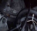
Is that a TVR variant Adam?  On the SD1 it goes to the engine block as per the bottom earth on this piccy.
and one of the two BW wires connected to the ring tag at the bottom of this image too.

The other BW wire on the same ring tag, comes from pins 5, 16, 17 and 35 on the ECU multiplug as seen here

The B wire on the second ring tag, I'm pretty sure, comes from the main and fuel pump relays. At least, from the diagrams, that appears to be the only possible source because the relays are integrated in the Efi loom and use that engine stud as the nearest convenient earthing point.
The loom itself is a strategically important electrical part of the System in the way the earths are all connected to the same place to prevent any spurious signals upsetting the sensor(s).
adam quantrill said:
get an ohmmeter on each CTS wire from the ECU to CTS plug, and wiggle the loom about.
That's for sure!  And for every other sensor being tested.
mrzigazaga said:
Hi Mate..That noise sounds a bit like an exhaust blow at the flange joint..I dont think anything at the bottom of the engine would make that kind of noise..The top maybe..Lifters or valves or cam..Although i could be wrong but it does sound like a blowing exhaust as its more of a ticking..Have you checked around the lower joins...Ziga
Hi ZigaThe exhaust is a mess mate, there are untightened bolts in the manifold on that side and really at a later stage i was going to remove and refix and as you say if it was the top end i would agree that it does sound like a lifter is stuck, i,ll post another video later mate with the drive belts removed to try and reduce the area noise, cheers mate here's hoping it a simple fix, many thanks, ralph
honestjohntoo said:
Shoot!!! So you are using a short circuit instead of 200 ohms.
Well that might explain the poor performance under load because the ECU would be significantly under fuelling, methinks, and the torque would be completely pants.
That's new to me as I never came across anyone choosing to do this with a short cicuit AND run the car, thus connected, so its a bit of an unknown to me.
I only ever heard of using a short circuit to briefly eliminate a wiring issue but I personally don't recommend it.
It does however beg the question as to whether the connector is actually making contact with the sensor or perhaps even the sensor is still duff.
One of the problems that occurs when an owner/enthusiast takes random steps outside the normal processes/recommendations and at the same time confuses helpers with arbitrary descriptions, is that odd or non understandable results may occur or possibly even collateral damage.
Not trying to scare you, but other components in the system might not like it.
There does come a time when a better all round understanding of the system is imperative.
Hi JohnWell that might explain the poor performance under load because the ECU would be significantly under fuelling, methinks, and the torque would be completely pants.
That's new to me as I never came across anyone choosing to do this with a short cicuit AND run the car, thus connected, so its a bit of an unknown to me.
I only ever heard of using a short circuit to briefly eliminate a wiring issue but I personally don't recommend it.
It does however beg the question as to whether the connector is actually making contact with the sensor or perhaps even the sensor is still duff.
One of the problems that occurs when an owner/enthusiast takes random steps outside the normal processes/recommendations and at the same time confuses helpers with arbitrary descriptions, is that odd or non understandable results may occur or possibly even collateral damage.
Not trying to scare you, but other components in the system might not like it.
There does come a time when a better all round understanding of the system is imperative.
Well i read that fix on here and as you know am new to TvR so if i have made a mistake then sorry to lead you up the garden path, i,ll get a 200 ohms resistor today and try again and (quote) the poor performance under load because the ECU would be significantly under fuelling, methinks, and the torque would be completely pants) would be bang on the money.
Many thanks
Ralph
Hi Adam
I,ll give that a go and thanks, can you tell me if it possible to remove the loom as a hole inculding the ECU plug, as then i could pull it apart a check the wirers and replace if needed, thanks for your help, regards, Ralph
honestjohntoo said:
adam quantrill said:
The CTS is not earthed at the block.
Is that a TVR variant Adam? On the SD1 it goes to the engine block as per the bottom earth on this piccy.adam quantrill said:
get an ohmmeter on each CTS wire from the ECU to CTS plug, and wiggle the loom about.
That's for sure! And for every other sensor being tested.Evening Guys
Well i think i have some good news, the noise coming from the engine is the broken starter parts being ficked around in the bell housing, so fishing rod out at the weekend and hope remove the unwanted items.
I have also managed to get some 175 ohm & 200 ohm resistors ( not sure which is the correct one to use as 2 Pdfs state different ohms), so i,ll try both to see if i can get the mixure somewhere near and try to find this wiring fault with the CTS
Cheers
Ralph

Evening Guys
Well on saturday managed to get most of the broken starter motors bits out of the gearbox so thank god thats sorted, but for the life of me i can not figure out what the issue is with the poor runing of the engine, i have check all wiring back to ecu and earthing pionts and all appears to be good, so am left scratching my head, the CTS wiring is fine and a new sensor is fitted, but to no avail, the car will not run with it connected??? so think its time to let a garage see what they can do, i await the large bill
Kind Regards
Ralph
Edited by ralph350i on Sunday 4th March 19:04
Gassing Station | Wedges | Top of Page | What's New | My Stuff