4CU ECU...Re-solder.
Discussion


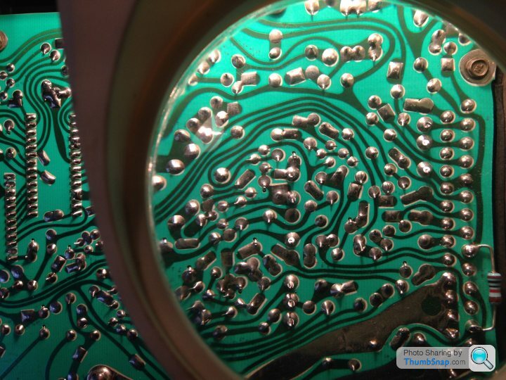
Hi peeps...After reading an article on the inevitable failings of the ECU i have given it to a very good friend to re-solder, Even though I'm not having any issues ..YET!.. I didn't want to fudge it up so its best left to those who know what they are doing!...As you can see in the following pics there is some corrosion on the inner board and there was some contamination within the unit..It seems that it has been repaired properly at some point as there are new main components fitted.
The numbers have been removed from the chips which is a bit weird but then it might possibly be to stop anyone replacing them again...
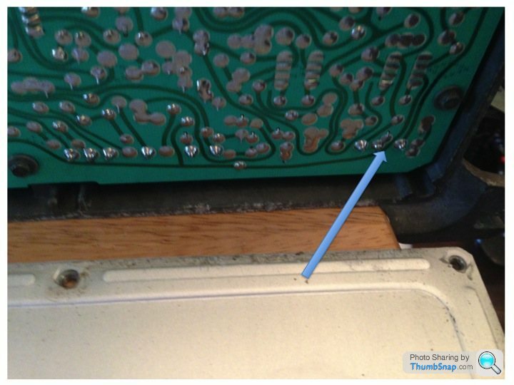
Moisture ingress
1.

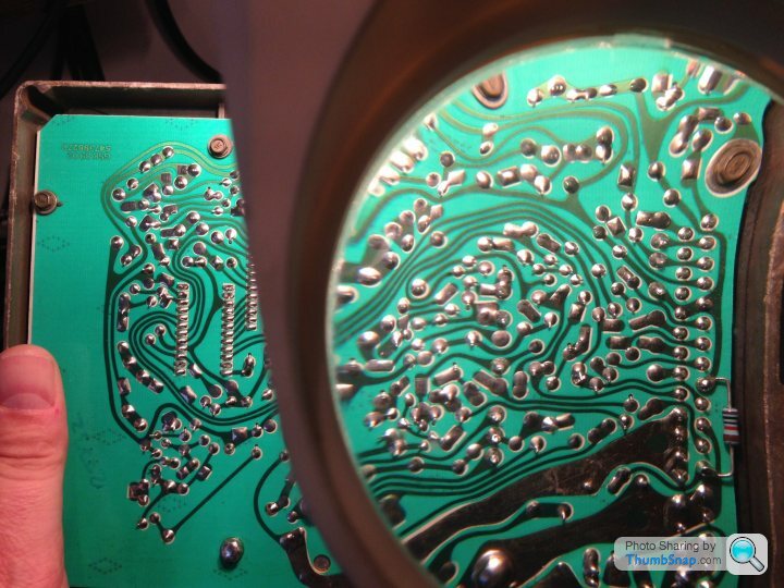
Corrosion on board
2.
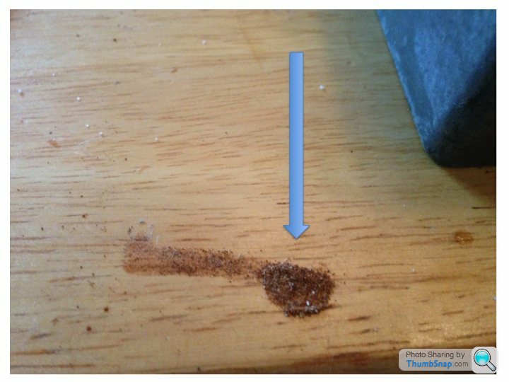
Sand or rust?
3.
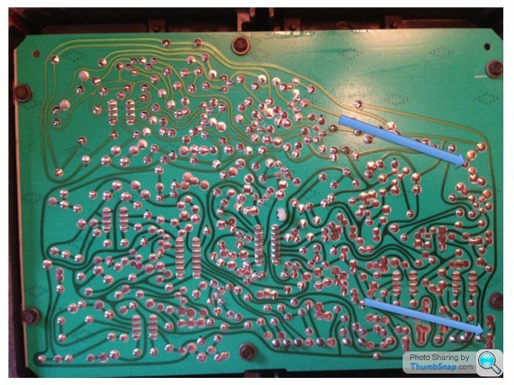
Dry joints
4.
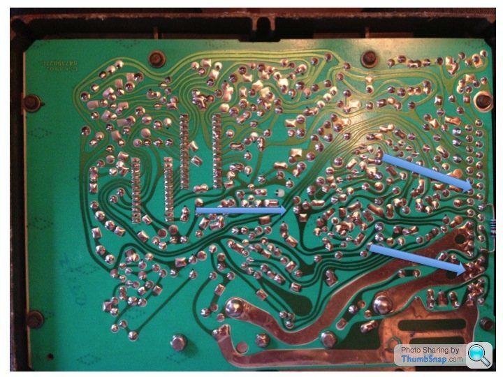
5.
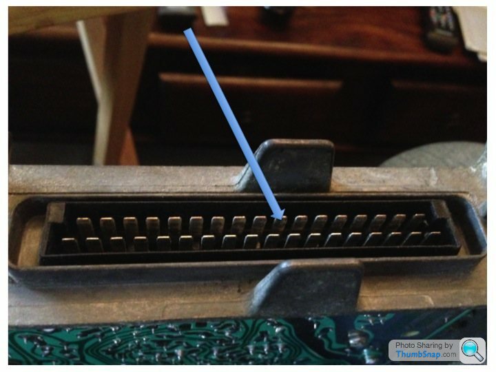
Minging connector pin
6.
Removed numbers?
7.
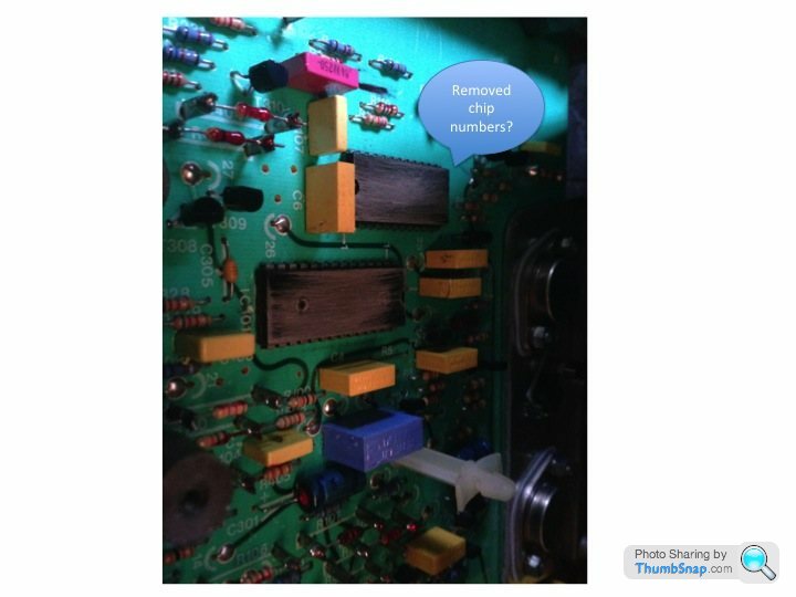
New heat sunk components.
8.
Thanks for looking...Ziga
The numbers have been removed from the chips which is a bit weird but then it might possibly be to stop anyone replacing them again...
Moisture ingress
1.
Corrosion on board
2.
Sand or rust?
3.
Dry joints
4.
5.
Minging connector pin
6.
Removed numbers?
7.
New heat sunk components.
8.
Thanks for looking...Ziga
Hi mate..Yeah it is hard to tell in the pics..But my friend is using a large magnifier so its easier for him to see..I have a receipt somewhere which says that the ECU was refurbed back in 2008 as part of an elimination process to cure a mis-fire that couldn't be traced..Its only happened to me a couple of times this year and TBH it hasn't re-appeared since a couple of cable ties were put around the unit holding the plug in place..Best to nip it in the bud as they say...It is a bit strange to see the numbers removed from the chips...Its not like they are specially designed...Cheers...Ziga
Edited by mrzigazaga on Sunday 19th October 12:20
Hmmm, technically the ICs were specially designed: that was early days for large-scale IC architecture and Ferranti specialised in custom ICs (ask Clive Sinclair!).
If the ICs have clear lacquer over them then the removal of markings was probably done at the factory; if you're looking directly at the chip's top surface then someone's done it since, probably to add an air of mystery
If the ICs have clear lacquer over them then the removal of markings was probably done at the factory; if you're looking directly at the chip's top surface then someone's done it since, probably to add an air of mystery
Wedg1e said:
Hmmm, technically the ICs were specially designed: that was early days for large-scale IC architecture and Ferranti specialised in custom ICs (ask Clive Sinclair!).
Thanks Ian for the info...I meant to say that the chips weren't specially designed for TVR....Or were they?Wedg1e said:
If the ICs have clear lacquer over them then the removal of markings was probably done at the factory; if you're looking directly at the chip's top surface then someone's done it since, probably to add an air of mystery
Very mysterious....But then i like mystery..
Well i have been informed its all done and dusted, And sealed to prevent any future moisture getting in..Should be able to collect it Monday or Tuesday...
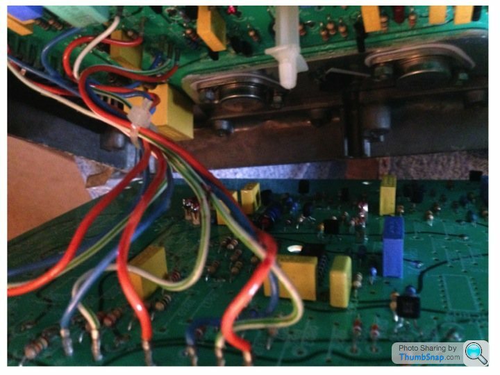
Does anyone know why this resistor has been put there..I have been informed its not usually there?...Perhaps a mod of some description?...Cheers...Ziga
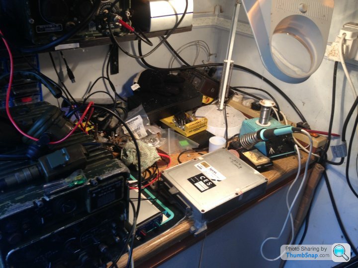
The workstation...(Come in No.5 your time is up..
 )
)
Edited by mrzigazaga on Sunday 19th October 14:00
Sometimes components pop up on odd places when there is a manufacturing defect (i.e. faulty track in the board).
Can't quite see the colours, looks like 11 ohms ?? (brown-brown-black), so could be a 'trim' type of thing.
Worked for Ferranti in 70 and 80's and they did do quite a bit of custom stuff, and made some very advanced chips and circuit boards for the day, but from what I saw they were all strongly marked with the "Ferranti" brand on the top. But then I was in the computer depts, not chip making or wiring.
I see the workstation has a proper professional Weller soldering station - Nice bit of kit, and should do a good job.
The resistor is connected across pins 5 (earth, 0V, ground, as you prefer  ) and pin 13, which is the input from the coolant tremperature sensor. So it's essentially the old frig to make the ECU believe the water's a different temperature than it really is.
By the look of it (allowing for monitor colour rendering) it's a '5-band' value of brown-black-black-red, or 100 and two 0s... 10KOhms.
) and pin 13, which is the input from the coolant tremperature sensor. So it's essentially the old frig to make the ECU believe the water's a different temperature than it really is.By the look of it (allowing for monitor colour rendering) it's a '5-band' value of brown-black-black-red, or 100 and two 0s... 10KOhms.
Wedg1e said:
The resistor is connected across pins 5 (earth, 0V, ground, as you prefer ) and pin 13, which is the input from the coolant tremperature sensor. So it's essentially the old frig to make the ECU believe the water's a different temperature than it really is.
By the look of it (allowing for monitor colour rendering) it's a '5-band' value of brown-black-black-red, or 100 and two 0s... 10KOhms.
So its a parasite then...Bugger....Would this of been done by Rover as i read something about it a while back...?) and pin 13, which is the input from the coolant tremperature sensor. So it's essentially the old frig to make the ECU believe the water's a different temperature than it really is.By the look of it (allowing for monitor colour rendering) it's a '5-band' value of brown-black-black-red, or 100 and two 0s... 10KOhms.
Cheers..Ziga
mrzigazaga said:
So its a parasite then...Bugger....Would this of been done by Rover as i read something about it a while back...?
Cheers..Ziga
Quite possibly (though more likely by Lucas or the company whose sticker is on the lid).Cheers..Ziga
Incidentally the 'minging' connector pin is 28, which is one of the injectors.
Wedg1e said:
The resistor is connected across pins 5 (earth, 0V, ground, as you prefer ) and pin 13, which is the input from the coolant tremperature sensor. So it's essentially the old frig to make the ECU believe the water's a different temperature than it really is.
By the look of it (allowing for monitor colour rendering) it's a '5-band' value of brown-black-black-red, or 100 and two 0s... 10KOhms.
Hmm, so would weaken fuel mixture a little ? Makes a lot of sense ....) and pin 13, which is the input from the coolant tremperature sensor. So it's essentially the old frig to make the ECU believe the water's a different temperature than it really is.By the look of it (allowing for monitor colour rendering) it's a '5-band' value of brown-black-black-red, or 100 and two 0s... 10KOhms.
Resistor colour codes as I remember them,only TWO significant digits, so
[brown brown black red] is 1 - 1 - (0 = number of following zeroes) red = 2% accuracy = 11 ohms
If it was 10K it would be brown-black-orange-[red/silver/gold] = 1-0-000 (3 zeroes) 2% or 10% or 5% accuracy
For water sender I guess to make a difference it would have to be in the 10's or 100's ohms ???
just sayin' not trying picking a fight.... this may be useful info for someone else, so good to get it as correct as possible...
Edited by RCK974X on Sunday 19th October 23:09
Edited by RCK974X on Sunday 19th October 23:19
RCK974X said:
Hmm, so would weaken fuel mixture a little ? Makes a lot of sense ....
Resistor colour codes as I remember them,only TWO significant digits, so
[brown brown black red] is 1 - 1 - (0 = number of following zeroes) red = 2% accuracy = 11 ohms
If it was 10K it would be brown-black-orange-[red/silver/gold] = 1-0-000 (3 zeroes) 2% or 10% or 5% accuracy
You'd be right if it was a 4-band code but you're overlooking the wide brown at the 'bottom' in the pic.Resistor colour codes as I remember them,only TWO significant digits, so
[brown brown black red] is 1 - 1 - (0 = number of following zeroes) red = 2% accuracy = 11 ohms
If it was 10K it would be brown-black-orange-[red/silver/gold] = 1-0-000 (3 zeroes) 2% or 10% or 5% accuracy
I've zoomed-in on the resistor and it definitely looks like brown-black-black-red-brown to me... so 10K at a 1% tolerance.
If it was 11 ohms then the ECU would scarcely 'see' the sender at all across it. The 10K adds a slight 'bypass' if you will to the sensor's 'cold' value but then has less and less contributory effect as the resistance of the sensor drops with temperature.
Thanks for the technical info....
Im now wondering if this attributed to my lean running and "Pinking" a while back with the solid state FPR?..Thats all stopped now i have an adjustable FPR...I did bring the psi up from 36 at WOT to 38, At the MOT the emissions were spot on.
Also if pin 28 is for an injector perhaps this was the cause of the mis-Fire, Maybe the two are linked, If the leaning off affected the injector with the faulty connection then that would make sense..I wonder if pin 28 is the left bank No.2 Cylinder as that was the plug i inspected..Sods law that on that day i only checked one plug...:roll eyes:

maston said:
Mr Fiddle would have done it for you mate
That just scares me... .....
.....
maston said:
Didn't fancy having a go yourself then ?
Well TBH mate..There is a risk of doing more damage with the heat of soldering iron and i wouldn't have a clue what was dry or not so i left it up to someone who knows what they are doing..DIY is good but it can also stand for " Destroy It Yourself "...Give me some gunpowder and a match and i know where I'm at...
Well after that cockup above, and apologies to Wedg1e for it....
Having a think about it, and by way of making up for my mistake....
If the temp sender is similar to Ford ECU ones, then a 10K resistor will affect (=weaken) the mixture more when cold than hot. This is because temp senders have higher resistance when cold than when hot, and fuel mixture is typically weakened by temperature, quite a bit when cold (=choke, sort of), and then by a small amount between 'normal hot' to 'very hot' (I hope that makes sense).
So if your wedge was running a bit rich, and especially when cold, this resistor would help - as per Adam's post.
That's based on stretching what I know about Ford ECU and assuming Lucas unit is similar - it probably is...
RCK974X said:
So if your wedge was running a bit rich, and especially when cold, this resistor would help - as per Adam's post.
Hi Andy..If anything mine was running lean when warm/Hot..Perhaps it was not working properly, I will hopefully see a difference when i fit it back on..Cheers...ZigaGassing Station | Wedges | Top of Page | What's New | My Stuff