Wedge Under Bonnet Pics
Discussion


Hi Marcus/Zig yes those photos do show the alt' mounted quite high up and it appears no mounting on the exhaust? So I guess the mounting was attached at the front to the timing case. I've just tried the same using the triangular plate with two tensioning bars joined together to reach the bottom of the alt'. It look horrible and not very secure. The only good thing being it lines up with the bottom pulley. Also there's not a lot of adjustment. Failing any other ideas, I think this will be the basis of the only position to mount it.
Cheers John C.
Cheers John C.
Hi all. Just an update to the saga. I managed to track down the previous owner who kindly gave me a bit of informative help. In his ownership the steering rack was, as fitted. However whilst the engine was being rebuilt he acquired a different block to rebuild the engine? That might account for the alternator mountings not fitting. The trick now is to see if my fabrications will work or even identify the block. At least it dispels any theory of a different rack being retro fitted. Cheers John C.
Again thanks for the pic of your brackets RCK974X. As you can see from my pics that steering bottom UJ is at a really steep angle to connect with the racks shaft. According to the previous owner it was with the car which he drove for some years. That's been the problem all along with the alternator which is now mounted on manufacture brackets but needs fabrication of the tension bar. The PAS pump as you can see is mounted on the nearside (Ford original position?) In the mists of time I reckon that steering rack has been replaced?
Here's a couple of pics hopefully showing the rack. There isn't any mounting holes for the PAS pump on the drivers side of the block?? Cheers John C.
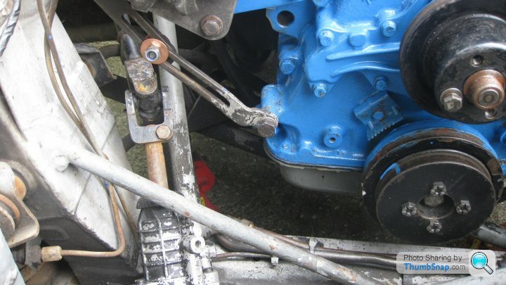
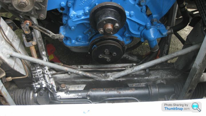
Here's a couple of pics hopefully showing the rack. There isn't any mounting holes for the PAS pump on the drivers side of the block?? Cheers John C.
Thanks Zig, it's the tension bracket that needs sorting as now, with my manufactured brackets, one to the timing case the other to exhaust mountings, the alternator sits quite high up, but at least it's in line with the pulleys and has enough movement to tension the belt. The tension bracket needs to be quite long to reach the timing case securing bolt hence the two temporary ones joined together in the pic. I agree that rack doesn't look original. Bit of a jigsaw this one? On a complete different tangent, can the PAS pump drive shaft seal be replaced as I've noticed a slight static leak running down the mounting plate. Not unexpected after 14 years of inactivity! At the moment I'm trying to work out which vacum/water pipes go where especially the drivers side of the pleumn chamber and a small diameter pipe from the cold start device which sits on the radiator top hose connection. Sorry for all the questions Zig. Maybe it would be better if I pm'd you with a list?  Cheers John C
Cheers John C Thanks Zig pics are good. OK, here's a list:
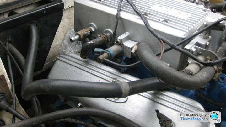
Expension tank has 3 x connections??
The second from the left is a small right angled hose. Don't seem to have a home for it?
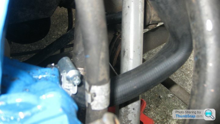
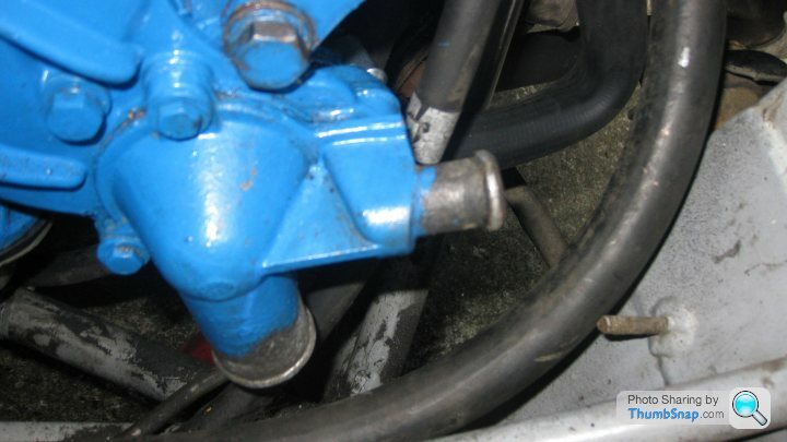
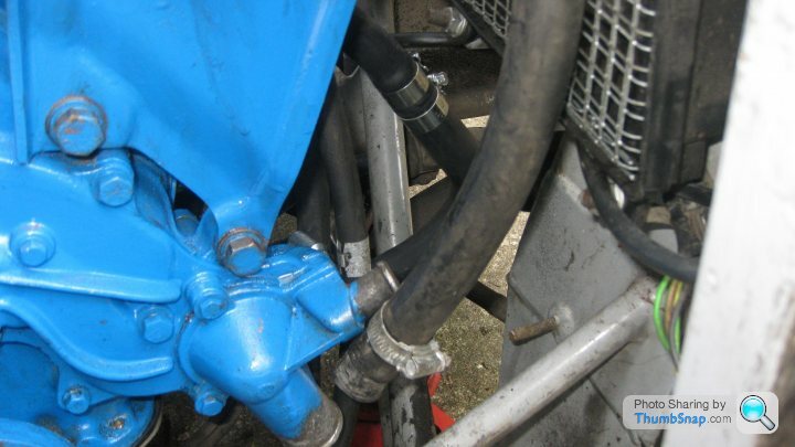
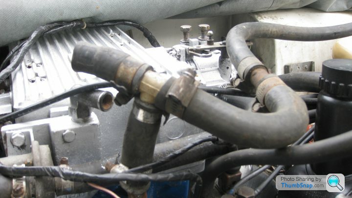
My thermostat housing at the front has a large connection to the bottom of radiator the other, connection to the heater? At the rear of the housing, a connection to the top of the engine adjacent to the cold start device?? Bit of bend in that one. Here's some more pics. Any thought on PAS pump shaft leaks Zig? Thanks for your time and patience. John C.
Expension tank has 3 x connections??
The second from the left is a small right angled hose. Don't seem to have a home for it?
My thermostat housing at the front has a large connection to the bottom of radiator the other, connection to the heater? At the rear of the housing, a connection to the top of the engine adjacent to the cold start device?? Bit of bend in that one. Here's some more pics. Any thought on PAS pump shaft leaks Zig? Thanks for your time and patience. John C.
Thanks Zig, connections are similar to mine but there are only two connections in/out of the radiator. Unless there is a small return under the filler cap. Will look later. I have the plastic tee piece with bits of hose on so will see where it might reach. One bit does seem to route towards that connection at the top of the block, which would then leave me with the connection at the rear of the thermostat housing, to where? At present this is connected to the top of the block? I still have the small right angled vaccum elbow on the drivers side of the pleugm to connect? Again I'm faced with unknow parts and what was taken off where. Thankyou for the offer of a PAS pump Zig, it might have to come to replacement if I can't reseal mine. Cheers John C.
Thanks Rick. I will sort out what pipes go where from your detailed info'. There are quite a few odd points about the Cologne coling system. In deed, why have an expanion tank? I sssume the radiator cap is just a cap, not a relief valve for pressure/vacuum? I have a long heater pipe on the nearside which seems to be formed to fit on the front of the thermostat housing. Would that be right? The rear connection from the stat' housing, at the moment is connected up to the top of the engine? Why? Is that a by-pass? The small right angled hose from the offside of the plenum casing I think is a breather for the crankcase? Where it connects, who knows!  Anyway cheers Rick, with your info I can at less start eliminating pipes and connections. John C.
Anyway cheers Rick, with your info I can at less start eliminating pipes and connections. John C.  Cheers John C.
 I thought I was the oldest on this forum?
  John C.
You hit the nail on the head Zig, "bits of hose lying around from the previous owner" As this project progress I'm made well aware that the past owner "collected" parts, not necessarily from the same vehicle! It started with the engine rebuild, different timimng case, water pump and has progressed through steering rack/alternator etc. I visited "Wesley" last night armed with Andy's pics. I've got a "T" assembly of hoses, which seem to live on top of the engine. That leaves the two heater hoses,(One down to the rear of the thermostat housing, the other to a valve on the drivers side of the plenum?) Two connections to the top of the header tank. One to a connection on the radiator, (If there is one) the other conection an overflow? I still have another assembly of hoses joined together with another "T" piece! I think more pics needed. John C.
It started with the engine rebuild, different timimng case, water pump and has progressed through steering rack/alternator etc. I visited "Wesley" last night armed with Andy's pics. I've got a "T" assembly of hoses, which seem to live on top of the engine. That leaves the two heater hoses,(One down to the rear of the thermostat housing, the other to a valve on the drivers side of the plenum?) Two connections to the top of the header tank. One to a connection on the radiator, (If there is one) the other conection an overflow? I still have another assembly of hoses joined together with another "T" piece! I think more pics needed. John C. That would get rid of two chuffing pipes.
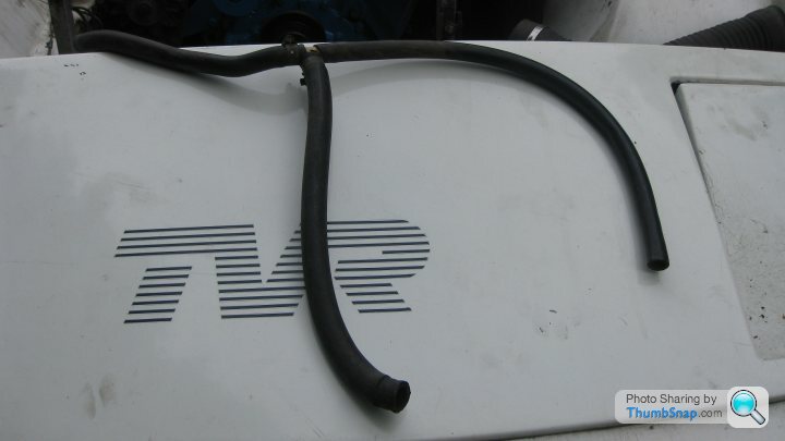
Thanks Zig that drawing will help in finding the correct passage of coolant. As promised, I 've attached the two pipe setups that came with the car. Both with "T" pieces. One seems fit on the top of the engine block with a longer pipe heading to the expension tank. I thought to the bottom of the tank but it's not the right size. I'm not sure about other "T" piece with pipes connected, maybe not from this engine? The nearside heater pipe seem to fall naturally to the rear thermostat housing. The drivers side heater pipe again seems to fit onto the valve at the top of the engine. Correct or not? Thanks again for time and patience. John C.
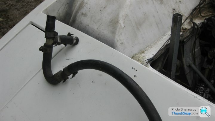
Thanks Zig. No, the large pipe hanging down by the thermostat. is from the heater matrix, nearside. So early I repositioned that pipe around the rear of the engine to the valve on the pleum casing drivers side. The other heater pipe, I repositioned again around the rear of the engine to the nearside. This I think I can connect to the T piece I already have, as those connections then fit to the expansion tank and down to the rear thermostat.. That would. match your diagram? The other T connect looks correct on the top of the engine? I'm not sure about the breather pipe? Is that the small right angled rubber pipe from the pleum, drivers side? The two rocker covers, alloy ones, I thought were a set? I have, what might be the original ones which are the usual tin ones. Look horrible! If that pipe is a breather can I modify the offside rocker cover? I believe there is already a very small union. (1/8") in the top of the cover. Yes I will be replacing the old hoses. Thanks again Mate, I think there's light at the end of the coolling tunnel. John C.
Thanks Andy for the offer of more pics but I think Zigs lastest flow diagram more or less cracks it making sense at last. I'm glad you confirm that it more or less follows your layout. Anyway, I thought water flowed the other way in the Southern hemisphere? Coriolis effect and all that.  Sorry, early morning humour Andy. However you've confirmed yet another part of my purchase being from an EFI engine; the alloy rocker covers. That i/2" right angled rubber union from the offside plenum is a breather which connected into the original o/s rocker cover? On the alloy cover there is a very small pipe union, perhaps I can modify that? Other than that pipe I can't see any other breather from the rocker covers. One step forward and all that.
 Only two more questins, not related to coolant systems. Can PAS pump drive shaft seals be replaced? What size battery do I need to fit offside by the brake servo please? Many thanks Andy. John C.
Sorry, early morning humour Andy. However you've confirmed yet another part of my purchase being from an EFI engine; the alloy rocker covers. That i/2" right angled rubber union from the offside plenum is a breather which connected into the original o/s rocker cover? On the alloy cover there is a very small pipe union, perhaps I can modify that? Other than that pipe I can't see any other breather from the rocker covers. One step forward and all that. Only two more questins, not related to coolant systems. Can PAS pump drive shaft seals be replaced? What size battery do I need to fit offside by the brake servo please? Many thanks Andy. John C.Thanks Ziga. I've just pulled the RH rocker cover off to compare with the steel one. Guess what, the securing holes don't match. Lucky I decided to fit the alloy ones during the rebuild. Anyway both covers inside have a baffle/ guard over the hole but the steel cover has a rubber gromet with a check valve in the pipe union. As you say it should be too much of a problem to enlarge the hole in the alloy cover and fit the check valve, then connect to the plenum. Problem solved? Or am I being to confident? Won't be able to "Wesley" over the weekend, windsurfing again now my broken toe as healed. Probably will be in A & E by Monday Cheers Mate, John C.
Thanks Andy/Zig. Yes, I was very surprized to find my other set of tin rocker covers not matching the alloy ones. Begs the question are the heads original given the plenum connection? The check valve is lightly loaded so when plumbed into the plenum it should keep a slight negative pressure in the system, no turbo Ziga. I've yet to research a battery but the space by the brake servo is not big height or length wise so its a matter of what will fit with the largest CCA. John C.
The check valve is lightly loaded so when plumbed into the plenum it should keep a slight negative pressure in the system, no turbo Ziga. I've yet to research a battery but the space by the brake servo is not big height or length wise so its a matter of what will fit with the largest CCA. John C. Gassing Station | Wedges | Top of Page | What's New | My Stuff