Two Stage Fan Switch - Simple Solution?
Discussion


adam quantrill said:
...how about putting it in the air path into the heater box? Then air will be drawn over it by the fan, cooling the resistor and warming the air into the bargain.....
Great minds think alike 
v8s4me said:
.....I was planning to locate the resistor inside the heater air intake scoop for that very reason...
adam quantrill said:
..... Then air will be drawn over it by the fan, cooling the resistor and warming the air into the bargain....
Hadn't thought of that benefit though. I could also make toast soldiers with it phillpot said:
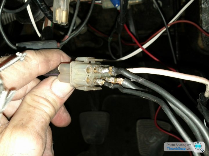
....Out of interest, did the resistor wire (in first photo) not work?....
Not really, no appreciable difference in fan speed. Probably just as well considering how much heat the ballast resistor is chucking out.Penelope Stopit said:
....No you can't fit that ballast resistor to create a 1st speed. ....

Edited by v8s4me on Friday 3rd March 20:42
In answer to your question, if you were to wire a starter motor in series with a headlight bulb and power up that circuit, the headlight bulb would illuminate at full brightness and no more, the starter could not possibly draw 200 to 300 Amps through the headlight bulb, the headlight bulb would draw its normal operating current through the starter. Wiring a HRS as a resistor in series with the blower motor will be similar to wiring 2 blower motors in series, hence the current draw of the blower motor will be reduced by half
All of the above is calculated with my tired brain so must be taken as approximate values. A true in practice calculation can be carried out by using the HRS resistance measured with a meter or by measuring the current draw of the HRS and then the current draw of the blower motor.
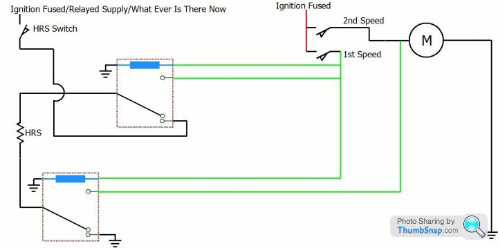
This is how it would work
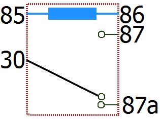
The diagram shows the relays as un-energised,HRS circuit as standard, when switching to 1st speed the circuits in green kick in (See 2 x Relays), the HRS is removed from its standard circuit and connected in series with the supply from the 1st speed switch to the blower motor. When needing to use the HRS the blower would need to be switched to 2nd speed, if needing to use the HRS the chances are that the blower 2nd speed would be needed for demisting the front screen so the circuit modification doesn't create an inconvenience

All of the above is calculated with my tired brain so must be taken as approximate values. A true in practice calculation can be carried out by using the HRS resistance measured with a meter or by measuring the current draw of the HRS and then the current draw of the blower motor.
This is how it would work
The diagram shows the relays as un-energised,HRS circuit as standard, when switching to 1st speed the circuits in green kick in (See 2 x Relays), the HRS is removed from its standard circuit and connected in series with the supply from the 1st speed switch to the blower motor. When needing to use the HRS the blower would need to be switched to 2nd speed, if needing to use the HRS the chances are that the blower 2nd speed would be needed for demisting the front screen so the circuit modification doesn't create an inconvenience
Edited by Penelope Stopit on Friday 12th May 08:01
Penelope Stopit said:
In answer to your question, if you were to wire a starter motor in series with a headlight bulb and power up that circuit, the headlight bulb would illuminate at full brightness and no more, the starter could not possibly draw 200 to 300 Amps through the headlight bulb, the headlight bulb would draw its normal operating current through the starter. Wiring a HRS as a resistor in series with the blower motor will be similar to wiring 2 blower motors in series, hence the current draw of the blower motor will be reduced by half
All of the above is calculated with my tired brain so must be taken as approximate values. A true in practice calculation can be carried out by using the HRS resistance measured with a meter or by measuring the current draw of the HRS and then the current draw of the blower motor.
This is how it would work
The diagram shows the relays as un-energised,HRS circuit as standard, when switching to 1st speed the circuits in green kick in (See 2 x Relays), the HRS is removed from its standard circuit and connected in series with the supply from the 1st speed switch to the blower motor. When needing to use the HRS the blower would need to be switched to 2nd speed, if needing to use the HRS the chances are that the blower 2nd speed would be needed for demisting the front screen so the circuit modification doesn't create an inconvenience
HiAll of the above is calculated with my tired brain so must be taken as approximate values. A true in practice calculation can be carried out by using the HRS resistance measured with a meter or by measuring the current draw of the HRS and then the current draw of the blower motor.
This is how it would work
The diagram shows the relays as un-energised,HRS circuit as standard, when switching to 1st speed the circuits in green kick in (See 2 x Relays), the HRS is removed from its standard circuit and connected in series with the supply from the 1st speed switch to the blower motor. When needing to use the HRS the blower would need to be switched to 2nd speed, if needing to use the HRS the chances are that the blower 2nd speed would be needed for demisting the front screen so the circuit modification doesn't create an inconvenience
Edited by Penelope Stopit on Friday 3rd March 23:32
Theoretically provided the blower motor and HRS are of equal or similar load ratings then your modification will work perfectly , however on a practical level I have a few reservations
Most wedges (95%)are of the DHC variety(no HRS) so your modification is a non starter for us , those with Fixed heads would be ok.
However the thought of hacking into a perfectly good electrical circuit for the HRS in order to try to create a fix for another totally separate circuit for blower motor speed doesn't sit well with me. It adds another level of complication into the system which isn't really required.
Dumping energy into the HRS to lower the fan speed is all well and good in the depths of winter but during the summer and its 25 degrees out do you want to have the HRS heating the back window because you've got the blower on low ??
It could be problematic for later owners who are not aware of the modification as well - I certainly wouldn't be happy to find a load of non standard wiring stuffed in behind the dash and have to un ravel what its for .Also would it occur to you that the reason the slow speed on your heater fan doesn't work anymore is because the element on your HRS has failed? It wouldn't to me.
So on a theoretical level your modification works fine but I wouldn't do it to my pride and joy
Loving your diagrams though
Cheers Ron
Ok everyone your starter for ten: What happens if you've got the blower on low and you switch the HRS on ??
Edited by Rockettvr on Saturday 4th March 23:16
Edited by Rockettvr on Saturday 4th March 23:25


phillpot said:
I think those wires were Fords way of doing Ballast Coil rather than use the Lucas resistor.
They were; the Tasmin 2.8 had a length of blue wire with bullet connectors, in series with the coil feed. It was bypassed during cranking. Sometimes it was coiled-up, sometimes it was left straight and taped into the loom.phillpot said:
My "Electrics" here, two in series would obviously reduce the voltage further but would two in parallel half the load (and therefore heat) but give same 7 volts?
Bearing in mind that those fine engineers at TVR put a pair in parallel just to do the dash lights on the S Series
MikeBearing in mind that those fine engineers at TVR put a pair in parallel just to do the dash lights on the S Series
A long time since I discarded the lamp resistors on mine, but I seem to recall they were in series, the idea being the rotary switch by-passed both resistors or switched in one or both of them depending if you wanted your dashboard lamps, dim, very dim or very very dim.

Oldred_V8S said:
but I seem to recall they were in series, the idea being the rotary switch by-passed both resistors or switched in one or both of them depending if you wanted your dashboard lamps, dim, very dim or very very dim.
Hi Paul, you must have more switch positions than me!I've got OFF - DIM - ON
Those old ballast resistors have been replaced with a nice neat wire wound item........
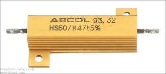
library picture, not necessarily correct value
In hindsight the old resistors could have been in series not parallel, I may have tweaked them at some stage because series would be dimmer than a dim thing on a dim day
Penelope Stopit said:
....The Heated Rear Window Element could be wired in series with the fan switch for a slow speed
The resistance of the HRS element on my car is 4 Ohms, twice that of ballast resistor. So unfortunately that wouldn't leave a lot of volts to work the fan and possibly overheat the screen. Good idea in theory though.Rockettvr said:
Penelope Stopit said:
In answer to your question, if you were to wire a starter motor in series with a headlight bulb and power up that circuit, the headlight bulb would illuminate at full brightness and no more, the starter could not possibly draw 200 to 300 Amps through the headlight bulb, the headlight bulb would draw its normal operating current through the starter. Wiring a HRS as a resistor in series with the blower motor will be similar to wiring 2 blower motors in series, hence the current draw of the blower motor will be reduced by half
All of the above is calculated with my tired brain so must be taken as approximate values. A true in practice calculation can be carried out by using the HRS resistance measured with a meter or by measuring the current draw of the HRS and then the current draw of the blower motor.
This is how it would work
The diagram shows the relays as un-energised,HRS circuit as standard, when switching to 1st speed the circuits in green kick in (See 2 x Relays), the HRS is removed from its standard circuit and connected in series with the supply from the 1st speed switch to the blower motor. When needing to use the HRS the blower would need to be switched to 2nd speed, if needing to use the HRS the chances are that the blower 2nd speed would be needed for demisting the front screen so the circuit modification doesn't create an inconvenience
HiAll of the above is calculated with my tired brain so must be taken as approximate values. A true in practice calculation can be carried out by using the HRS resistance measured with a meter or by measuring the current draw of the HRS and then the current draw of the blower motor.
This is how it would work
The diagram shows the relays as un-energised,HRS circuit as standard, when switching to 1st speed the circuits in green kick in (See 2 x Relays), the HRS is removed from its standard circuit and connected in series with the supply from the 1st speed switch to the blower motor. When needing to use the HRS the blower would need to be switched to 2nd speed, if needing to use the HRS the chances are that the blower 2nd speed would be needed for demisting the front screen so the circuit modification doesn't create an inconvenience
Edited by Penelope Stopit on Friday 3rd March 23:32
Theoretically provided the blower motor and HRS are of equal or similar load ratings then your modification will work perfectly , however on a practical level I have a few reservations
Most wedges (95%)are of the DHC variety(no HRS) so your modification is a non starter for us , those with Fixed heads would be ok.
However the thought of hacking into a perfectly good electrical circuit for the HRS in order to try to create a fix for another totally separate circuit for blower motor speed doesn't sit well with me. It adds another level of complication into the system which isn't really required.
Dumping energy into the HRS to lower the fan speed is all well and good in the depths of winter but during the summer and its 25 degrees out do you want to have the HRS heating the back window because you've got the blower on low ??
It could be problematic for later owners who are not aware of the modification as well - I certainly wouldn't be happy to find a load of non standard wiring stuffed in behind the dash and have to un ravel what its for .Also would it occur to you that the reason the slow speed on your heater fan doesn't work anymore is because the element on your HRS has failed? It wouldn't to me.
So on a theoretical level your modification works fine but I wouldn't do it to my pride and joy
Loving your diagrams though
Cheers Ron
Ok everyone your starter for ten: What happens if you've got the blower on low and you switch the HRS on ??
Edited by Rockettvr on Saturday 4th March 23:16
Edited by Rockettvr on Saturday 4th March 23:25
If a vehicle has a fold-down or removable hood, the vehicle does not need a cooling fan running in the summer, this method is only for vehicles with a fixed roof
What do you think to this?
Edited by Penelope Stopit on Tuesday 14th March 08:28
Penelope Stopit said:
Regarding your thoughts on my above circuit. My diagram looks simple and in practice is very simple to wire up, anyone using my method would only need to run 2 wires from the fan switch and 1 wire from the heated rear screen to the relays. As for the temperature of the heated rear screen churning out heat in the summer, this is the same as having a resistor fitted inside the heater box, the blower motor does blow air across the resistor in the heater box and that heated air does flow into the vehicle
If a vehicle has a fold-down or removable hood, the vehicle does not need a cooling fan running in the summer, this method is only for vehicles with a fixed roof
What do you think to this?
HiIf a vehicle has a fold-down or removable hood, the vehicle does not need a cooling fan running in the summer, this method is only for vehicles with a fixed roof
What do you think to this?
Edited by Penelope Stopit on Tuesday 14th March 08:28
The installation of your modification is indeed quite simple - but the point I was attempting to get across was not that it was in anyway difficult but that hacking into a completely unrelated circuit in order to try to bodge a fix in the heater control circuit is a no-no for me. Add in the unwanted side effects of modifying in this way means you create far more immediate and future issues than you're solving when a suitably sited ballast resistor could achieve ( it doesn't have to go in the heater box it only has to have adequate airflow to dissipate the heat that it generates)
In short its a complicated way of solving a problem that only creates more problems of its own - hardly an ideal solution
Rockettvr said:
In short its a complicated way of solving a problem that only creates more problems of its own - hardly an ideal solution
 I know, why not do what TVR did: coil up a few feet of wire on the back of the switch
The Americans allegedly spent hundreds of thousands of dollars inventing a pen that would write any way up, for their astronauts... the Russians used a pencil. Simple problems demand simple solutions.
Rockettvr said:
Penelope Stopit said:
Regarding your thoughts on my above circuit. My diagram looks simple and in practice is very simple to wire up, anyone using my method would only need to run 2 wires from the fan switch and 1 wire from the heated rear screen to the relays. As for the temperature of the heated rear screen churning out heat in the summer, this is the same as having a resistor fitted inside the heater box, the blower motor does blow air across the resistor in the heater box and that heated air does flow into the vehicle
If a vehicle has a fold-down or removable hood, the vehicle does not need a cooling fan running in the summer, this method is only for vehicles with a fixed roof
What do you think to this?
HiIf a vehicle has a fold-down or removable hood, the vehicle does not need a cooling fan running in the summer, this method is only for vehicles with a fixed roof
What do you think to this?
Edited by Penelope Stopit on Tuesday 14th March 08:28
The installation of your modification is indeed quite simple - but the point I was attempting to get across was not that it was in anyway difficult but that hacking into a completely unrelated circuit in order to try to bodge a fix in the heater control circuit is a no-no for me. Add in the unwanted side effects of modifying in this way means you create far more immediate and future issues than you're solving when a suitably sited ballast resistor could achieve ( it doesn't have to go in the heater box it only has to have adequate airflow to dissipate the heat that it generates)
In short its a complicated way of solving a problem that only creates more problems of its own - hardly an ideal solution
I can't be reading back through the topic now but do seem to recall that I suggested mounting a ballast resistor under-bonnet, I could be getting confused though and posted the idea to another topic. Thanks for your thoughts on this, I appreciate opinions
Gassing Station | Wedges | Top of Page | What's New | My Stuff