Discussion


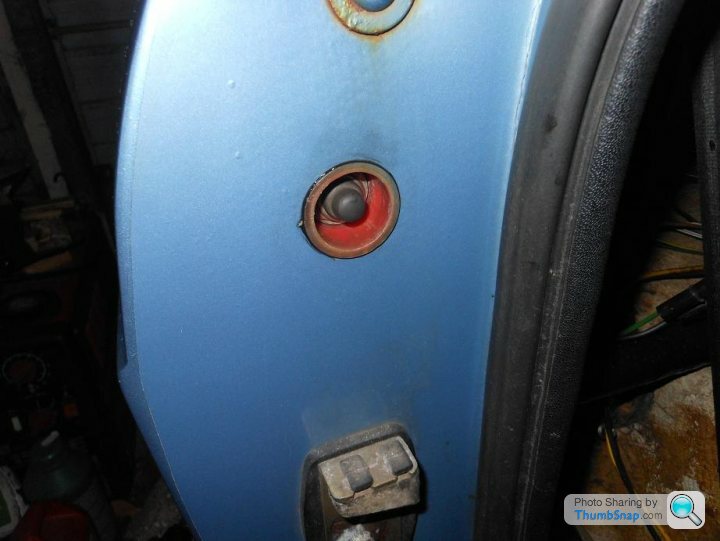
New boot release switch...
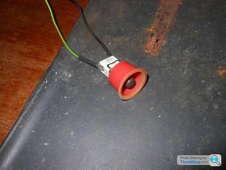
I was quite amused to find that I could get a new switch exactly the same as the original, 30 years on.
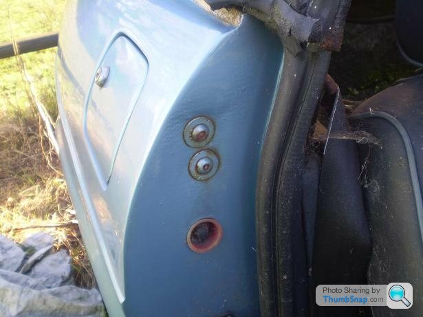
Also amused that the housing appears to be something like a discarded piece of aerosol can lid, and it was held in with black goo...
so keeping it original!
I was quite amused to find that I could get a new switch exactly the same as the original, 30 years on.
Also amused that the housing appears to be something like a discarded piece of aerosol can lid, and it was held in with black goo...
so keeping it original!
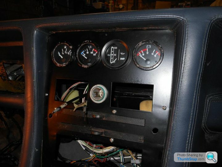
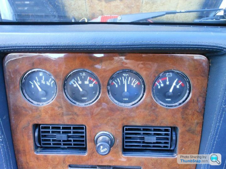
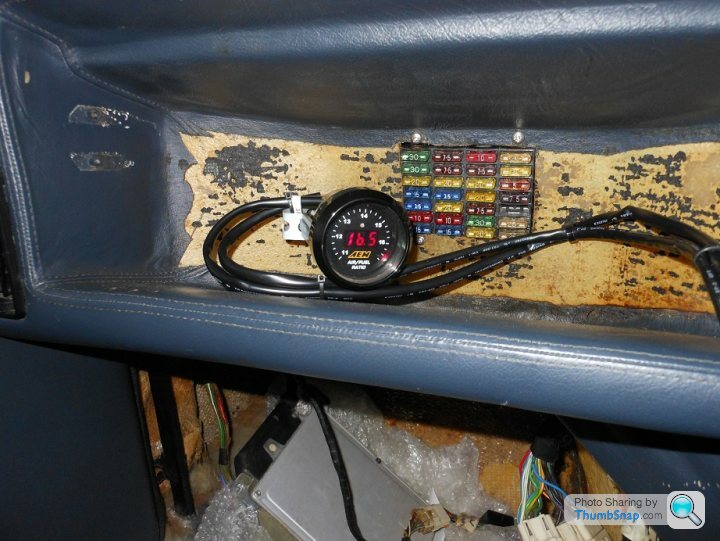
Finally got around to refitting the original oil pressure gauge after substituting a known working one when working on the engine, so I now have matching gauges again albeit with some 'patina'
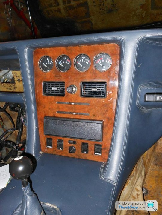
The heater control cables have been hanging out of the dash for ages; I got around to connecting them up to the dash sliders not thinking that they would work but amazingly they do... there's no doubting that this is a hand built car when you look at the heater controls!
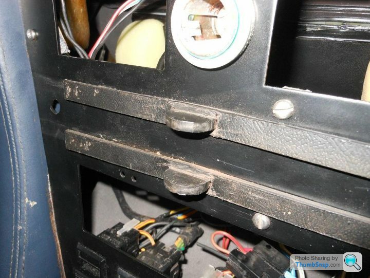
The heater control cables have been hanging out of the dash for ages; I got around to connecting them up to the dash sliders not thinking that they would work but amazingly they do... there's no doubting that this is a hand built car when you look at the heater controls!
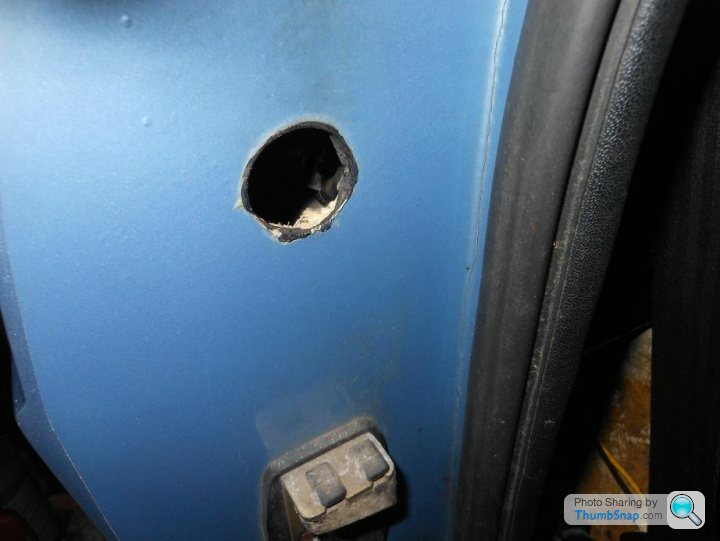
I love the table leg thing, thay clearly ran out of old table legs for my car! Though on a more serious note, cutting a hole in Kevlar is bl**dy hard and making a square hole would be a right pain in the wotsit. If you try and drill Kevlar it resists the drill and tears, if you need a neat hole you need to grind it out. This is probably yet another reason that TVR dropped the kevlar body idea.
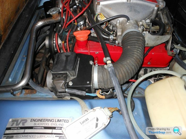
Fun and games with oil pressure senders for the gauge.
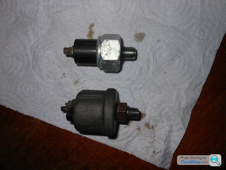
Top one is the one for the later 'TVR' branded gauges (fitted as a known working set), bottom one is for the 1986 ish VDO type. Top is a 1/2" UNF thread, bottom is 1/8" NPT. The thread in the engine is 1/2"UNF, but you can't get a VDO sensor with that thread, so you need an adaptor. This is what was on the SEAC...
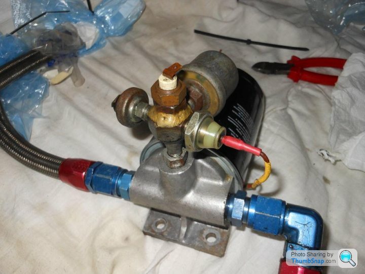
Somewhat bespoke! There's also an oil temperature sender in there but there was no gauge for that, plus two oil pressure switches. Something to do with the dry sump system I guess; there's two seperate oil pressure lights on the dash.
The VDO sensor is toast so I've ordered another, fortunately they are freely available from the likes of Merlin. I also found a 1/2"UNF to 1/8"NPT adaptor to suit the surrogate engine, so when I fit the original engine I'll be able to swap everything over... It'll be interesting to see what pressure the dry sump system works at!
Top one is the one for the later 'TVR' branded gauges (fitted as a known working set), bottom one is for the 1986 ish VDO type. Top is a 1/2" UNF thread, bottom is 1/8" NPT. The thread in the engine is 1/2"UNF, but you can't get a VDO sensor with that thread, so you need an adaptor. This is what was on the SEAC...
Somewhat bespoke! There's also an oil temperature sender in there but there was no gauge for that, plus two oil pressure switches. Something to do with the dry sump system I guess; there's two seperate oil pressure lights on the dash.
The VDO sensor is toast so I've ordered another, fortunately they are freely available from the likes of Merlin. I also found a 1/2"UNF to 1/8"NPT adaptor to suit the surrogate engine, so when I fit the original engine I'll be able to swap everything over... It'll be interesting to see what pressure the dry sump system works at!
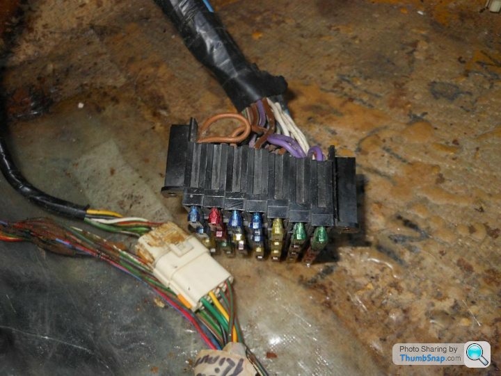
Fuse box reattached to the back of the glove box, araldite did the trick with the lugs.
New Goodridge brake hoses... someone can't count:
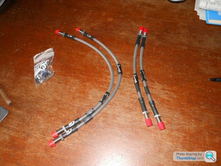
Only three are required... so I have a surplus of rear hoses. I changed them because the pedal was a little soft, but it hasn't made a difference. I'm suspecting that the new aftermarket master cylinder that I've fitted is not much good, so I need to investigate getting a new old stock Girling part or maybe get the original resleeved; I'm suspicious of both old rubber seals and also new poor quality seals, so I'm not quite sure what to do.
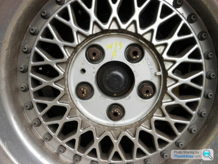
I was also reminded of the somewhat bespoke wheel nuts; they are all drilled to different sizes. I guess it's to make the weight of each nut the same. Someone has lavished a lot of attention on this car!
New Goodridge brake hoses... someone can't count:
Only three are required... so I have a surplus of rear hoses. I changed them because the pedal was a little soft, but it hasn't made a difference. I'm suspecting that the new aftermarket master cylinder that I've fitted is not much good, so I need to investigate getting a new old stock Girling part or maybe get the original resleeved; I'm suspicious of both old rubber seals and also new poor quality seals, so I'm not quite sure what to do.
I was also reminded of the somewhat bespoke wheel nuts; they are all drilled to different sizes. I guess it's to make the weight of each nut the same. Someone has lavished a lot of attention on this car!
Edited by The Hatter on Monday 17th April 22:46
Adam, not really, it just seems to have a lot of travel, at least compared to the 350i. It does have different front calipers to the 350i but still Ford ones so I wouldn't expect it to feel much different.
Pumping it does help a bit so I suspect there's still some air in the system somewhere. I'll try different methods of bleeding it to see if I can improve it before I do anything drastic.
Pumping it does help a bit so I suspect there's still some air in the system somewhere. I'll try different methods of bleeding it to see if I can improve it before I do anything drastic.
Slow movement but moving forward -
I'm happy with the megasquirt conversion on the 350i but I'm not completely sold on it. It's very good (in fact stunningly good) when the engine is warm, but cold starting and particularly hot starting leaves a little to be desired; plus a stable idle is elusive. My conclusion is that it's well worth converting to megasquirt on an average car but the SEAC is somewhat special... so I thought I'd spend some time trying to fettle the original SEAC flapper system.
So... I was running Chris's 420 engine with (I think) standard 350i injectors, uncertain parentage ECU and 400SE flapper AFM; It ran OK in that state. I have recently been trying to run with the original SEAC ECU but it's been running badly; until I substituted a good Jaguar large bore AFM (very hard to find a good one, long story!!)...
So now it's running pretty well again, with the original SEAC ECU and a good Jaguar AFM (there's many different types, you have to get the right one!). At idle it reads very lean, but I think that's actually a rich misfire that shows lean due to poor combustion in some cylinders and therefore oxygen in the exhaust... this is the AFR at idle - and I don't believe it!
So now I'm on the verge of rebuilding and refitting the original engine in the knowledge that the ECU and fuel injection system is where I want it to be... winter project time.
Hi Graham,
I did look at the 14CUX stuff but it doesn't really carry over to megasquirt for all kinds of reasons, and all engines differ in detail anyway (compression, cams etc). My 350i does start and run well when cold, but on hot starts it doesn't run as well as I'd like it to. I think the problem is that the air temperature sensor in the inlet duct doesn't reflect the temperature of the air entering the cylinders when the engine is hot after a hot start.
I notice that the hotwire CUX system has a fuel temperature sensor on the fuel rail that the flapper CU system doesn't; that is probably something to do with hot starting - I don't think a typical MS system can use that sensor, although I suspect there will be experts out there who can program it to do so.
I also wonder if the CUX system has some kind of timed algorithm after a hot start that alters the air temp sensor output and therefore the fueling while the plenum is hot; as slowly the plenum will cool down with the engine running and pulling in cold air.
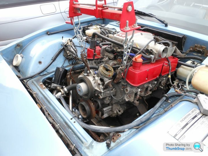
Finally things are moving forward, in a two steps forward one step back kind of way...
I'm being indecisive about the ECU so I want to keep my options open for megasquirt or flapper, so I need a trigger wheel on the crankshaft. The original SEAC crank pulley had to be fitted to the surrogate engine due to tight clearances to the additional chassis strengthening braces, and I needed to take the pulley off to get the trigger wheel fitted. However those chassis braces mean you can't get the crank pulley off without unbolting the engine from the chassis and raising the engine... so that was the job for this weekend.
Engine lifted;
Pulley off;
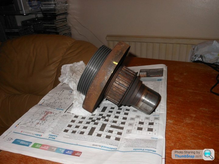
There's just about enough room on the back of the pulley for a trigger wheel between the damper and the dry sump pump drive, but it's very tight!
I'm being indecisive about the ECU so I want to keep my options open for megasquirt or flapper, so I need a trigger wheel on the crankshaft. The original SEAC crank pulley had to be fitted to the surrogate engine due to tight clearances to the additional chassis strengthening braces, and I needed to take the pulley off to get the trigger wheel fitted. However those chassis braces mean you can't get the crank pulley off without unbolting the engine from the chassis and raising the engine... so that was the job for this weekend.
Engine lifted;
Pulley off;
There's just about enough room on the back of the pulley for a trigger wheel between the damper and the dry sump pump drive, but it's very tight!
That's a codeword not a crossword, still not very good though! I'm very aware of the need for cleanliness, if it's something I will clean up at some point I'll use towels/sheets, otherwise it'll be newspaper or plastic sheets/bags.
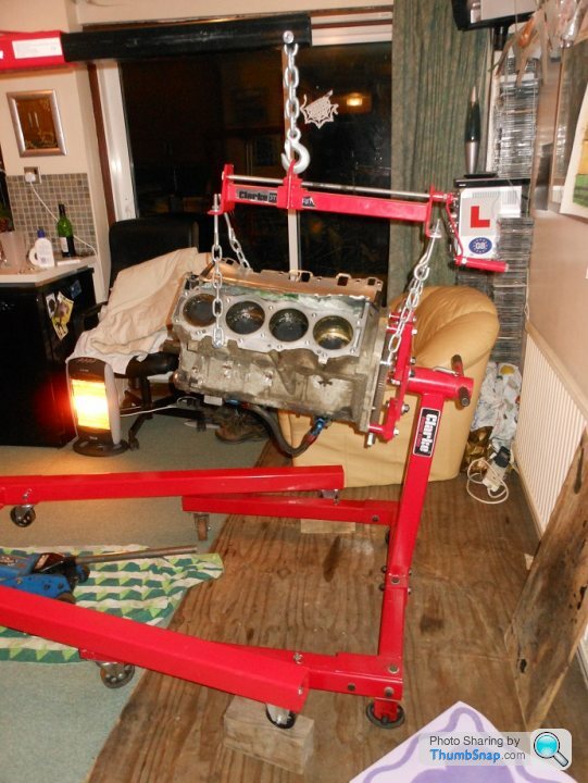
The engine is now on a stand, you'd think that a Clarke engine crane would have it's legs positioned such that a Clarke engine stand would tesselate with it and allow you to use them both - but no. Blocks of wood and jacks needed!
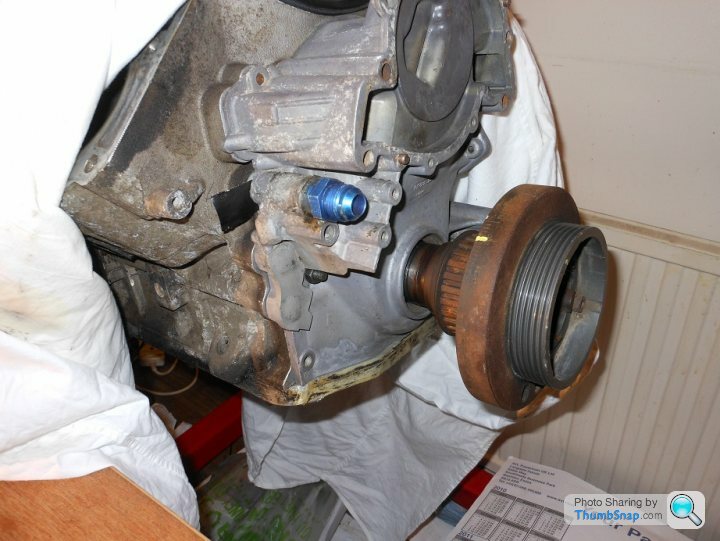
The front cover is interesting, adapted to suit the dry sump system with welding and machining to remove the oil pump/filter features. Not very neat but it does the job.
The engine is now on a stand, you'd think that a Clarke engine crane would have it's legs positioned such that a Clarke engine stand would tesselate with it and allow you to use them both - but no. Blocks of wood and jacks needed!
The front cover is interesting, adapted to suit the dry sump system with welding and machining to remove the oil pump/filter features. Not very neat but it does the job.
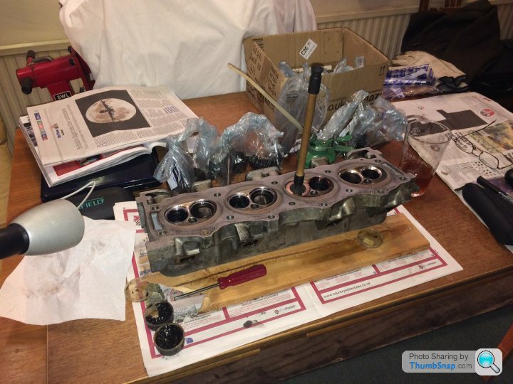
Cylinder head work...
The valve guides need replacing/sleeving, I was about to take them to be done when I realised that there were shims in the valve pockets - good practice on high performance engines with extreme cams. They were difficult to get out due to the capillary action of the oil behind them, I got a couple of strong magnets from an electric motor and managed to get them out:
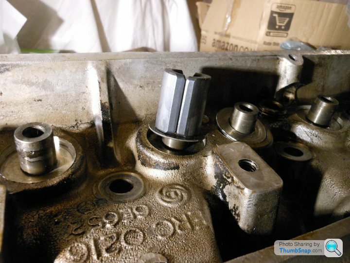
Some of them had a curious radial groove pattern on them, I'm not sure what that's about!
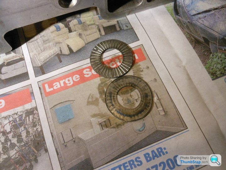
There was quite a variation in the shim thicknesses:
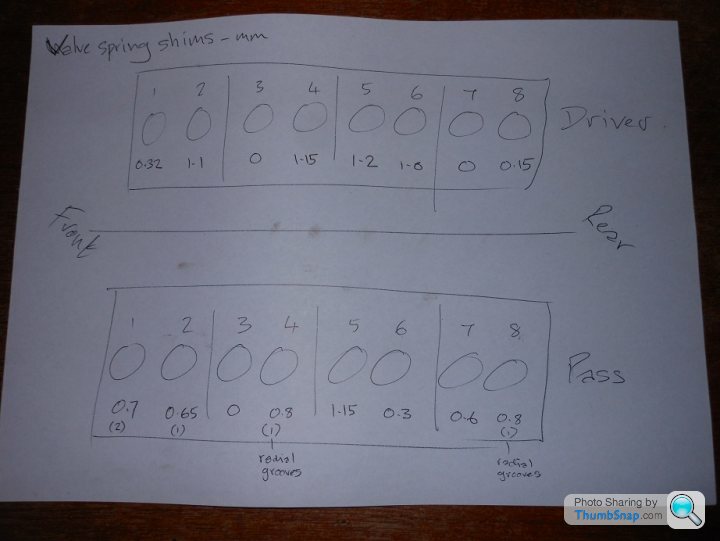
I intend to put them back as they came out.
The valve guides need replacing/sleeving, I was about to take them to be done when I realised that there were shims in the valve pockets - good practice on high performance engines with extreme cams. They were difficult to get out due to the capillary action of the oil behind them, I got a couple of strong magnets from an electric motor and managed to get them out:
Some of them had a curious radial groove pattern on them, I'm not sure what that's about!
There was quite a variation in the shim thicknesses:
I intend to put them back as they came out.
The shims are completely flat, just with grooves in them. I did a bit of googling, and it appears the intent is to allow oil to flow across the shim and reduce the heat transfer from the cylinder head to the valve spring. Sounds optimistic to me!
Only a few of the shims have these grooves so I'd guess they were selected based on thickness, and some just happened to have grooves in them.
I'm planning to have K-Line valve guide liners installed. Hopefully that will not upset the concentricity of the valve seats to the guides, and will mean that the valve seats will not have to be recut.
The heads are ready now, time to move on to the block. The cam bearings are worn and need replacing, so I need to strip the bottom end to get access. The dry sump pan is off...
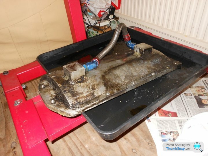
The bottom end has been assembled with some care, there's lots of evidence of fettling...
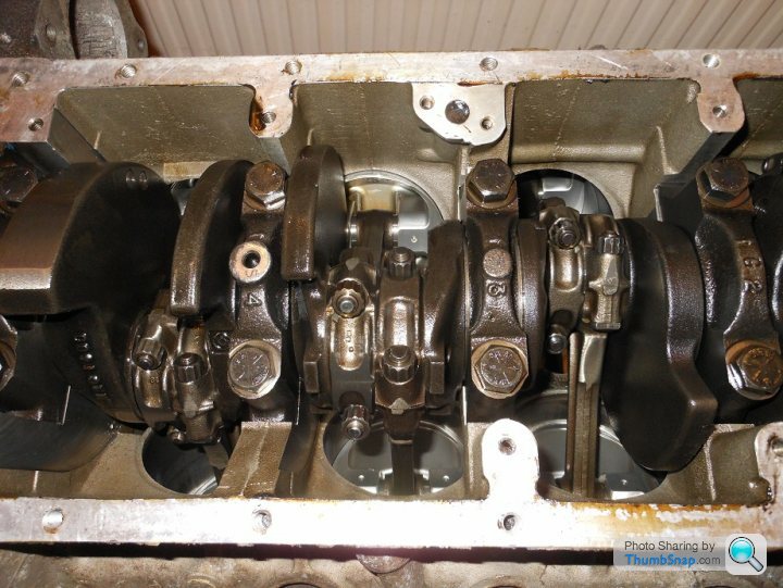
I'm hoping the crank journals are OK... but I suspect it'll need a regrind.
The bottom end has been assembled with some care, there's lots of evidence of fettling...
I'm hoping the crank journals are OK... but I suspect it'll need a regrind.
Gassing Station | Wedges | Top of Page | What's New | My Stuff