G40R 2.5 litre Duratec
Discussion


Pipes sorted, so now on to the wiring. First the engine loom, which needs wires adding as follows: upgrade from 2 wire to 3 wire cam position sensor, cam actuator wires, oil temperature gauge wire, wiring for new STACK oil pressure gauge.
To remove the engine loom you first need to take away the air box and windscreen washer bottle to disconnect the 47 pin bulkhead connector. Remove the throttle bodies from the inlet manifold. Remove the alternator. Then you are free to take off and dissect all this spaghetti.
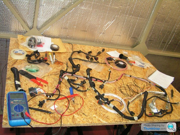
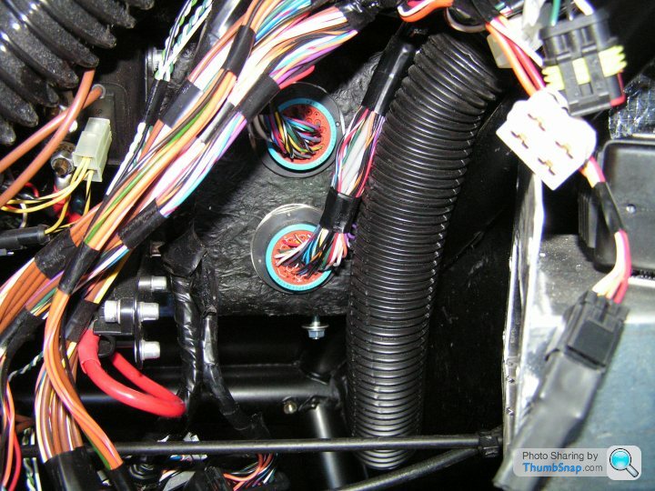
After a lot of careful splicing and continuity checking we end up with a modified loom like this.Some extra pins are needed in the 47 way bulkhead connector. There are enough spare holes available for this. These are Deutsch DTM pins (and sockets) available from PoleVolt, for example. It’s also very handy to have the insertion/extraction tool. I think I got that from RS. The bulkhead connectors are from the Deutsch HDP20 series. It’s all on the web if you search around.
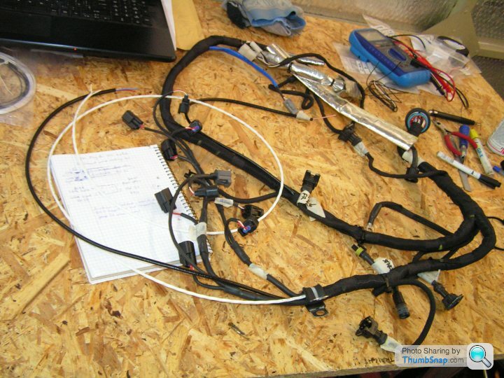
At the top of the picture, the blue sleeved tail with DTM connector on the end is for the STACK gauge sensor and oil warning switch. Near it, there is a black sleeved tail with a single pink wire at the end for the oil temperature sender, located in the sump. That’s waiting for a spade connector.
At the left of the picture is a long white wire coiled up. That is a 3 core screened cable for the cam position sensor. This will be trimmed to length and connector added later after re-fitting to the engine. Near that is a long black tail with red and blue wires at the end for the cam actuator.
Take lots of pictures and label everything when you are ripping this loom apart. Tracing the original wires is arduous, as they are all white, black or red.
I refitted the engine loom and amazingly the engine still ran without frying any of the electronics.
With relief I moved finally to the dashboard and ECU wiring.
To remove the engine loom you first need to take away the air box and windscreen washer bottle to disconnect the 47 pin bulkhead connector. Remove the throttle bodies from the inlet manifold. Remove the alternator. Then you are free to take off and dissect all this spaghetti.
After a lot of careful splicing and continuity checking we end up with a modified loom like this.Some extra pins are needed in the 47 way bulkhead connector. There are enough spare holes available for this. These are Deutsch DTM pins (and sockets) available from PoleVolt, for example. It’s also very handy to have the insertion/extraction tool. I think I got that from RS. The bulkhead connectors are from the Deutsch HDP20 series. It’s all on the web if you search around.
At the top of the picture, the blue sleeved tail with DTM connector on the end is for the STACK gauge sensor and oil warning switch. Near it, there is a black sleeved tail with a single pink wire at the end for the oil temperature sender, located in the sump. That’s waiting for a spade connector.
At the left of the picture is a long white wire coiled up. That is a 3 core screened cable for the cam position sensor. This will be trimmed to length and connector added later after re-fitting to the engine. Near that is a long black tail with red and blue wires at the end for the cam actuator.
Take lots of pictures and label everything when you are ripping this loom apart. Tracing the original wires is arduous, as they are all white, black or red.
I refitted the engine loom and amazingly the engine still ran without frying any of the electronics.
With relief I moved finally to the dashboard and ECU wiring.
There needs to be a single extra terminal inserted in the ECU plug at A26 for the cam actuator signal, plus a few new terminals in the bulkhead to match what was done to the engine loom for oil pressure & temperature gauges. ECU terminals came from SCS Delta. SCS also had to do a small soldering job on the Tornado ECU board to reconfigure it from the 2 wire to 3 wire cam sensor.
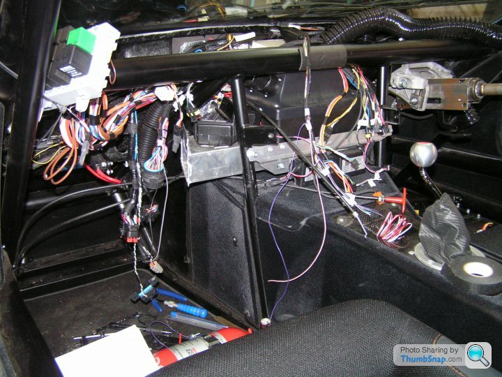
With the dashboard panel removed, the heater fan is blocking access to the bulkhead connector.

Having removed the ECU and heater fan, there is access to all the wiring. The lower of the two bulkhead connectors is for the engine.
The blue wire for the cam actuator signal continues from bulkhead to ECU pin A26. Then a few more wires from bulkhead to instruments. The original fuel gauge was a bad joke, so this has been swapped for a Racetech oil temperature gauge. The connection at the back of the Racetech gauge is exactly the same as the original fuel gauge, so all that needs to be done is to splice in the wire from the oil temp sender instead of the fuel tank sender. The STACK oil pressure gauge has its own plug to be added to the loom.
With the dashboard panel removed, the heater fan is blocking access to the bulkhead connector.
Having removed the ECU and heater fan, there is access to all the wiring. The lower of the two bulkhead connectors is for the engine.
The blue wire for the cam actuator signal continues from bulkhead to ECU pin A26. Then a few more wires from bulkhead to instruments. The original fuel gauge was a bad joke, so this has been swapped for a Racetech oil temperature gauge. The connection at the back of the Racetech gauge is exactly the same as the original fuel gauge, so all that needs to be done is to splice in the wire from the oil temp sender instead of the fuel tank sender. The STACK oil pressure gauge has its own plug to be added to the loom.
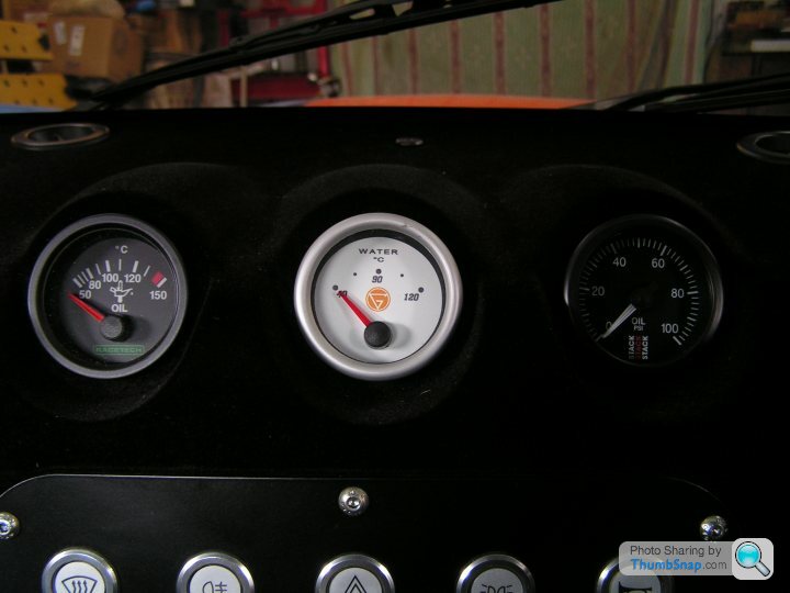
The original water temperature gauge is fed by a PWM output from the ECU, so I have kept that for the time being. I don’t like the white dial face though, or the lack of scale divisions. I’ll try to swap that out later.
Reason for the STACK oil pressure gauge is that the original Ginetta oil gauge was always reading low. When the brand new engine was also reading supposedly low pressure, I realised that it must be the gauge at fault, not the engines.
Reason for the STACK oil pressure gauge is that the original Ginetta oil gauge was always reading low. When the brand new engine was also reading supposedly low pressure, I realised that it must be the gauge at fault, not the engines.
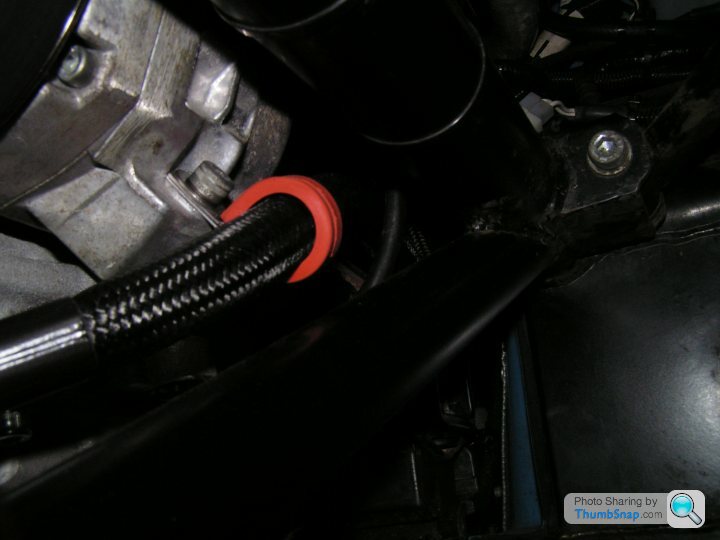
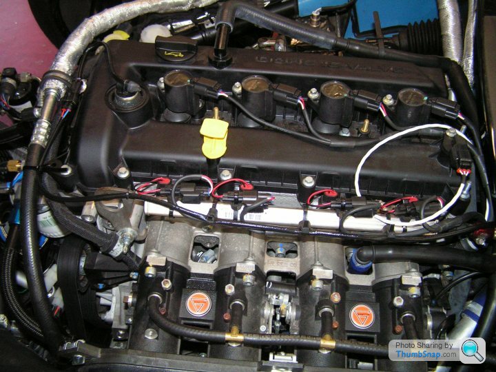
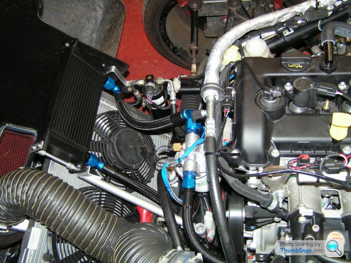
Engine loom connected up with cam sensor & actuator plugged in. The correct plug for the cam actuator does not seem to be readily available, so I used some “Superseal” female connector terminals to slide on to the pins inside, then potted and heat shrink sleeved to secure. The resulting tail leads to a Superseal connector located at the front of the cam cover.
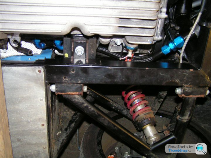
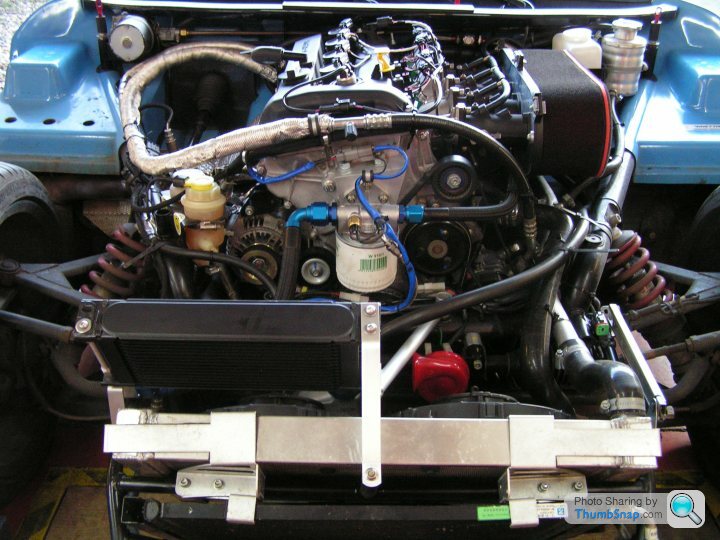
Overall view of cooler installed. Fits with just about perfect finger gap clearance to the closed bonnet. Not pictured, I have used some soft foam draught-excluder tape stuck to the bonnet to close the gap.
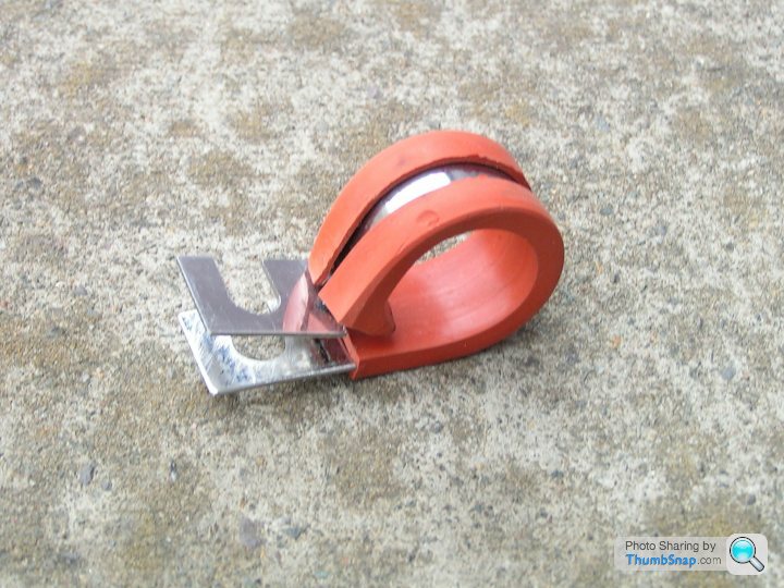
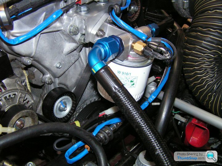
Remote filter mounted on bracket to timing cover. The blue loom goes along the -3 pipe to remote mounted STACK pressure sender. This filter mounting gives the shortest pipe run to the cooler and allows room for the larger filter which can easily be changed.
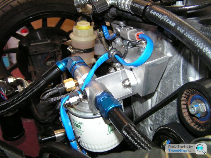
The filter is a Mann W916/1, which is a typical ¾” UNF Ford fitting for e.g. Capri 2.8i. It’s a good quality filter with pressure relief valve and anti-drain back valve. The oil pressure comes up instantly upon engine start, despite the long and large diameter pipes. Oil temperature remains below 100°C even on the rolling road.
Remote filter mounted on bracket to timing cover. The blue loom goes along the -3 pipe to remote mounted STACK pressure sender. This filter mounting gives the shortest pipe run to the cooler and allows room for the larger filter which can easily be changed.
The filter is a Mann W916/1, which is a typical ¾” UNF Ford fitting for e.g. Capri 2.8i. It’s a good quality filter with pressure relief valve and anti-drain back valve. The oil pressure comes up instantly upon engine start, despite the long and large diameter pipes. Oil temperature remains below 100°C even on the rolling road.
Off again to SCS Delta in Norfolk for proper rolling road calibration. The cam control wiring worked fine. Power was OK at about 210 BHP, but can see the lumpy torque curve and the torque dying off from 6500rpm, flow limited. That’s because of the under-sized throttles (45mm) carried over from the original 2 litre engine and the restrictive exhaust.
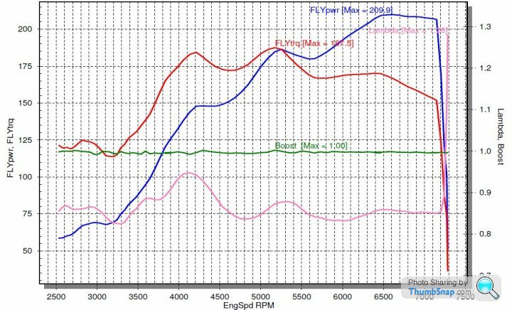
The uneven torque is probably down to the highly compromised exhaust, which is still the factory original. The inlet manifold is for the original 2 litre and there is a 5mm step up to the larger 2.5 inlet ports. There isn’t enough meat to easily open up the manifold. The throttles are 45’s where it needs 48’s or 50’s. All this needs to be fixed and the engine should be good for 250bhp +. The main thing is the healthy torque from 4000rpm up. The engine does not rely on high rpm, so it copes better with the wide-gapped original gearing and allows relaxed cruising in 5th. Debatable numbers aside, it drives a LOT quicker than the old 2 litre, which was supposed to be 175bhp, but probably wasn’t.
The uneven torque is probably down to the highly compromised exhaust, which is still the factory original. The inlet manifold is for the original 2 litre and there is a 5mm step up to the larger 2.5 inlet ports. There isn’t enough meat to easily open up the manifold. The throttles are 45’s where it needs 48’s or 50’s. All this needs to be fixed and the engine should be good for 250bhp +. The main thing is the healthy torque from 4000rpm up. The engine does not rely on high rpm, so it copes better with the wide-gapped original gearing and allows relaxed cruising in 5th. Debatable numbers aside, it drives a LOT quicker than the old 2 litre, which was supposed to be 175bhp, but probably wasn’t.
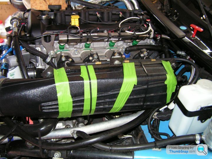
Opening the bonnet after the power runs, the air box lid was found to have separated from the mounting flange. We glued, taped and tie-wrapped it back on to the flange. Then another full power run showed much reduced mid-range torque and mid-range power down by about 25bhp, although only a small loss in top end power. I knew the air box was quite a poor design, but didn’t imagine it was THAT bad!
The calibration was left the same and at home I have now replaced the air box by the largest foam filter that Pipercross produce. It slots straight on to the existing back plate. The windscreen washer bottle will eventually have to find a new home.
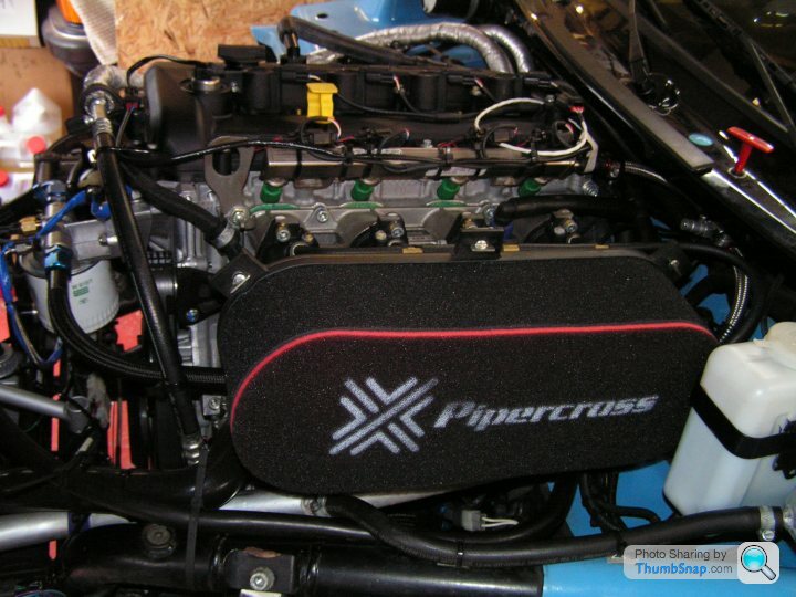
The calibration was left the same and at home I have now replaced the air box by the largest foam filter that Pipercross produce. It slots straight on to the existing back plate. The windscreen washer bottle will eventually have to find a new home.
Remembering back to the beginning of this saga, I looked at the invoice from Guglielmi Motorsport to see how many hours they charged me for the original engine swap. I did help out a bit with running around collecting parts for them to fit. Nevertheless, it was amazing how quickly and efficiently they did that job compared to the many hours of head scratching, trial and error etc that I used up finishing off all these details. So I can again recommend Guglielmi if you are in the Northants area. They are in Daventry.
Looking at the engine invoice from Raceline, most of the cost was the parts. The amount I could have saved in labour and machining by taking a DIY route was not worth all the personal time, trouble and research effort I would need to make. Plus I would have to farm out any machining and hope it was done correctly. Not worth it. The knowledge and support that came from Raceline as part of the engine package was invaluable. They are now working on some 48mm throttles for me, so more is still to come.
Looking at the engine invoice from Raceline, most of the cost was the parts. The amount I could have saved in labour and machining by taking a DIY route was not worth all the personal time, trouble and research effort I would need to make. Plus I would have to farm out any machining and hope it was done correctly. Not worth it. The knowledge and support that came from Raceline as part of the engine package was invaluable. They are now working on some 48mm throttles for me, so more is still to come.
In preparation for getting a new exhaust fitted, I decided to take a look at the metal tunnel sections running in the gap between the lower chassis rail and the body sill either side of the car. Also, a lot of road dirt and stones was flying forwards off the rear wheels and collecting on top of these tunnels, due to open inner rear arches. I wanted to clear the muck out and then fabricate some closure plates for the inner arches.
The tunnel sections for my car were secured unbelievably with zinc plated M6 button head screws, totally unsuitable for the harsh environment underneath a car. 5 screws each side fix the tunnels to the body sill. 6 screws each side fix them to the chassis. My car had done only 3000 miles, mostly dry and always garaged. However, the screws were factory fitted dry, with no assembly lube. The heads have only a shallow 4mm hexagon socket. It’s a guaranteed mess of seized in screws. After a good dose of penetrating oil, patience and persistence, all 10 of the sill screws came out. Of the 12 total into the chassis, only 4 could be carefully unscrewed. Remaining were 8 screws where the hexagon sockets just rounded out. No amount of hammering, chiselling would get these things to budge. Then it’s a case of welding nuts on to the button heads and trying to spanner them off, easing back & forth with doses of penetrating oil. That got another 6 out, though in some cases they initially sheared off and needed a new nut welding on to the screw stub. The welding heat also probably helps release the rust.
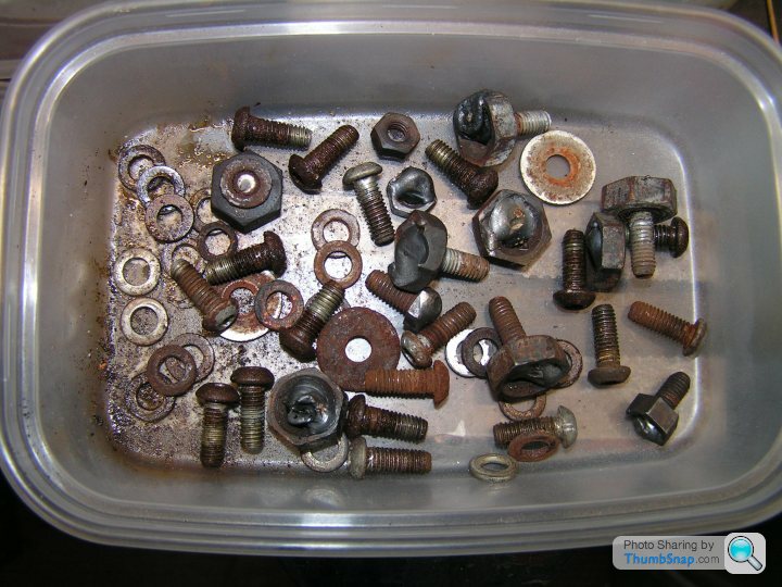
Finally, there were 2 screws with the heads sheared off and completely stuck in the chassis, both at the right rear where the exhaust pipe hangs on. I resorted to drilling though the fibreglass sill and through the screws with extra long drills, going 3, 4, 5mm in steps. The screws are tough, so had to keep re-sharpening the drills. Managed it in the end and cleaned up the tapped holes. All screws replaced by stainless and used hexagon heads in the chassis with lots of anti-seize. What a complete avoidable mess!!

The tunnel sections for my car were secured unbelievably with zinc plated M6 button head screws, totally unsuitable for the harsh environment underneath a car. 5 screws each side fix the tunnels to the body sill. 6 screws each side fix them to the chassis. My car had done only 3000 miles, mostly dry and always garaged. However, the screws were factory fitted dry, with no assembly lube. The heads have only a shallow 4mm hexagon socket. It’s a guaranteed mess of seized in screws. After a good dose of penetrating oil, patience and persistence, all 10 of the sill screws came out. Of the 12 total into the chassis, only 4 could be carefully unscrewed. Remaining were 8 screws where the hexagon sockets just rounded out. No amount of hammering, chiselling would get these things to budge. Then it’s a case of welding nuts on to the button heads and trying to spanner them off, easing back & forth with doses of penetrating oil. That got another 6 out, though in some cases they initially sheared off and needed a new nut welding on to the screw stub. The welding heat also probably helps release the rust.
Finally, there were 2 screws with the heads sheared off and completely stuck in the chassis, both at the right rear where the exhaust pipe hangs on. I resorted to drilling though the fibreglass sill and through the screws with extra long drills, going 3, 4, 5mm in steps. The screws are tough, so had to keep re-sharpening the drills. Managed it in the end and cleaned up the tapped holes. All screws replaced by stainless and used hexagon heads in the chassis with lots of anti-seize. What a complete avoidable mess!!
In true TVR fashion, the powder coating was flaking off too, so some time was needed to de-rust and epoxy paint these areas. This will no doubt be a continuous process, like painting the Forth Bridge!
To stop road dirt being thrown forwards into the sill void, I made some plastic closure panels which fit in front of the rear wheels, at the bottom of the inner wheel arch. This one is from the left (non-exhaust) side.
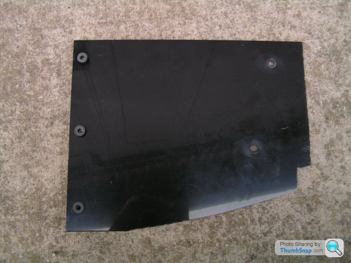
To stop road dirt being thrown forwards into the sill void, I made some plastic closure panels which fit in front of the rear wheels, at the bottom of the inner wheel arch. This one is from the left (non-exhaust) side.
At last, some more updates, this time on the exhaust catalyst and trying to pass the MOT emissions. The original factory Cat always passed with the original 2 litre engine, but the 2.5 was reading high on CO, no matter what. This was strange, as hydrocarbon emissions were minimal and the lambda was good and stable.
I found it really hard to reach anyone who could give definitive answers how to proceed, whether that be engine people, exhaust specialists or rolling roads. Duratec engines are also commonly used in the Caterham world, but there is effectively infinite space available to mount a Cat with the external exhaust arrangement of a Caterham. This compares to the G40 where there is very limited space to jam in the Cat behind the front wheel. Overall, this is an area of poor design in the G40. A few more inches of wheelbase would have allowed more room to package a decent exhaust.
Could only conclude that the original Ginetta Cat, rusty and scabby looking, perhaps had its day.
Next up was to try and get a new Cat pipe made. Local suppliers were booked up and somewhat equivocal anyway towards my emissions questions. Eventually I tried a custom exhaust supplier located in the northwest, who I used many years ago when living in that area. Previously, they ran a combined workshop and exhaust fitting business, with a lot of practical experience and timely service. Fast forwards 20 years or so and they had moved to a neighbouring town with more of a large scale factory operation and longer lead times. Oh well, I decided to give them a try.
The result was a new Cat pipe, plus a De-cat pipe for track use.
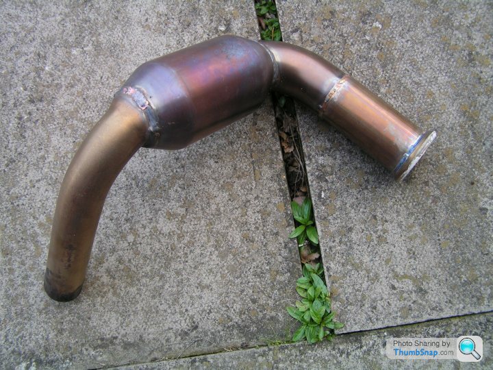
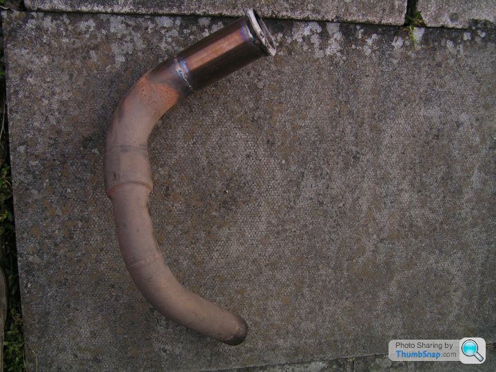
The result was a new Cat pipe, plus a De-cat pipe for track use.
Sadly, the emissions were no better than the old Ginetta Cat. Additionally, I had an unpleasant encounter with a very unfriendly MOT man who spent most of his efforts ranting and telling me off. How he came to be recommended to me by the local motorsports shop I will never know.
It turned out that the new Cat pipe was a Euro 3 standard Cat, which the northwest exhaust factory had somehow not realised was below spec for a 2014 car. Like I said, hard to find people who really know what the score is.
So if you want a job doing properly, sadly you often times have to do it yourself. A call to Jetex Exhausts yielded a Euro 5 Cat which they were able to supply as the mantle (core) only with a range of cones and adapters for me to try and make something fit into the cramped space. Neil at Jetex was a very helpful guy and gave good advice - thanks!
I also found a few other useful bits and pieces at Exhaust Parts UK.
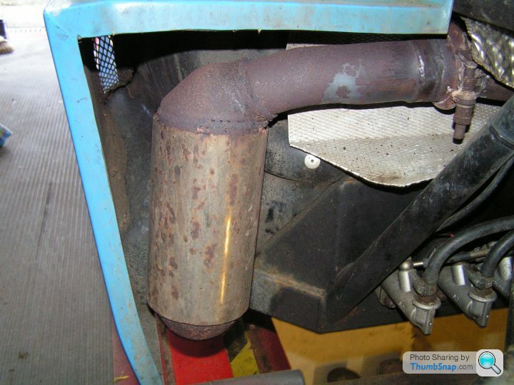
The result was the Frankenstein Twin Cat, combining the new Jetex Euro 5 Cat running horizontally direct off the manifold with the previous Euro 3 Cat bottom section. After all, I had paid for the E3 Cat and it wasn't like I was ever going to get my money back for it, so may as well use it.
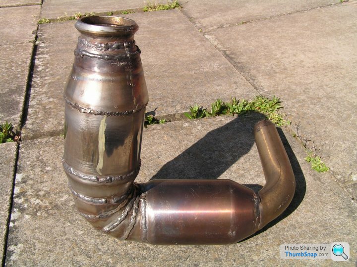
Sorry for my rough welding, but it does all hold together with no leaks. The inlet cone to the E5 Cat is intentionally offset, to keep the Cat away from the bodywork.
It turned out that the new Cat pipe was a Euro 3 standard Cat, which the northwest exhaust factory had somehow not realised was below spec for a 2014 car. Like I said, hard to find people who really know what the score is.
So if you want a job doing properly, sadly you often times have to do it yourself. A call to Jetex Exhausts yielded a Euro 5 Cat which they were able to supply as the mantle (core) only with a range of cones and adapters for me to try and make something fit into the cramped space. Neil at Jetex was a very helpful guy and gave good advice - thanks!
I also found a few other useful bits and pieces at Exhaust Parts UK.
The result was the Frankenstein Twin Cat, combining the new Jetex Euro 5 Cat running horizontally direct off the manifold with the previous Euro 3 Cat bottom section. After all, I had paid for the E3 Cat and it wasn't like I was ever going to get my money back for it, so may as well use it.
Sorry for my rough welding, but it does all hold together with no leaks. The inlet cone to the E5 Cat is intentionally offset, to keep the Cat away from the bodywork.
Gassing Station | Ginetta | Top of Page | What's New | My Stuff