Graphics interface for the 14CUX
Discussion


stevesprint said:
Colin & Dan - As you declined a donation for bring us all RoverGauge I decided to buy a very cheap SAAB 14CUX and have forward you the binary as requested.
Steve, thank you for the binary and I'm glad it was a "very cheap" unit. And thanks for updating me on your progress and results yesterday. It was exciting even way over here.I have already disassembled the code and noticed that the first thing in memory is the serial port service routine (in RV8 code, it's the last thing in memory). Everything is changed around. The serial port code does look the same as you may have guessed since you were able to connect for awhile. That big gray thing is a power resistor. It would be good to understand the hardware differences a little more. I'm amazed that the V8 ran on the SAAB unit.
Steve .. that revving to 2k then dropping abruptly and repeating is the ecu bringing in the fuel cut on overrun I think. I've seen that happen on the std tvr fit ecu when the idle airflow is too high .. limit the airflow on idle to under bring revs under say 2k and it doesn't happen. Obviously there needs to be a combination of factors which need to happen for fuel cut on overrun ie closed throttle and high airflow, something you normally wouldn't achieve at idle.
danbourassa said:
Steve, thank you for the binary and I'm glad it was a "very cheap" unit. And thanks for updating me on your progress and results yesterday. It was exciting even way over here.
I have already disassembled the code and noticed that the first thing in memory is the serial port service routine (in RV8 code, it's the last thing in memory). Everything is changed around. The serial port code does look the same as you may have guessed since you were able to connect for awhile. That big gray thing is a power resistor. It would be good to understand the hardware differences a little more. I'm amazed that the V8 ran on the SAAB unit.
It’s a pleasure; in fact it was exciting for me to. I’m very impressed you have disassembled the code and already got your head around it. Please do not hesitate to ask if you want me to carry out any further tests. I don't think you'll find many people that would be as brave as I was last night.I have already disassembled the code and noticed that the first thing in memory is the serial port service routine (in RV8 code, it's the last thing in memory). Everything is changed around. The serial port code does look the same as you may have guessed since you were able to connect for awhile. That big gray thing is a power resistor. It would be good to understand the hardware differences a little more. I'm amazed that the V8 ran on the SAAB unit.
Can anyone confirm it is actually based on a 14CUX and not a 14CU, I’ve never seen a 14CU.
Dan, try and not stay up all night working on that code. Enjoy, Steve
danbourassa said:
There are significant changes between LR and TVR maps, so no LR maps would probably work well in your Chim.
Danjr6yam said:
I was thinking more along the lines of using a later TVR ECU 
Further to jr6yam question do you have any examples of the LR and TVR map differences and are they significant enough to ignore Land Rovers fixes and improvements in Operation Pride. Do you know if the TVR mods were restricted to just the data or the code as well?
I’ve ported my TVR fuel map, adjustment factor and base idle to a Land Rover Revision 3383 and it drove surprisingly well. You rightly made me aware that the coolant, throttle, idle offset tables etc could also be different. I will never use the Land Rover Revision as the overrun sound track was muted, unless you can help turn it back on again, that noise never grows old.
Edited by stevesprint on Friday 6th September 08:16
danbourassa said:
Robert, I must apologize. You are correct (again)! I just got an email from a man who knows much. The checksum fixer location is at address 0xFFEB (or 0x3FEB on the programmer). This makes more sense. I have asked about why the first location was sometimes changed between upper and lower halves (which led to my confusion on this). Hopefully there will be an interesting answer.
Nice. I'll work on updating the tunerpro definition with all of the known addresses so far. It sounds like at times they had some hacks doing the programming updates. Thats funny that you've already found glitches. Have you all had any problems with your bench harness? Mine is controlling the check engine light and the engine control relay, but the serial looks like it is sending 1 packet then disconnecting. I have not hooked up any sensor inputs, so maybe the foating values are causing the problem. It also looks like my fault code reader is faulty. I'll have to verify everything works on my disco this weekend since its currently 50 miles from here.
I think I found the chip ID location.
Addresses 3FE9 and 3FEA when taken the hex value and converted to string match up to the chip list that Blitzracer posted a few pages back.
It appears my mystery early 90s range rover computer had 2665, my 95 Discovery that hasn't been to the dealer in 15 years has 3360. It must have missed operation pride. The 3604 chip contains... you guessed it, 3604
stevesprint said:
Am I correct thinking it is 14CUX based and not 14CU as it has the MVA5033KA chip? Also, could it be modified to run our favourite gang of 8? The most obvious components missing are the 2 blue capacitors and it has an extra grey capacitor instead. I’m not an electronics person so in my very basic terms I’m think maybe the missing 2 blue capacitor one for each bank & here one grey capacitor for one bank of 4.
Both the MVA5033 and MVA5033KA chips were used in the 14CUX, though the 'KA' part seems to appear only on later units. That chip is actually a PAL that performs address decoding to the various devices (ADC, PROM, and the PAL itself) and it also contains a small amount of RAM.Although the PAL's function is simple enough to deduce, we don't have a true map of its gate array. This is mainly because programmable logic parts are so quickly obsoleted by new technology that no one bothered to make the MVA5033's datasheet available after it was replaced by some ASIC or FPGA. It was originally made by Plessey, but after various buyouts and mergers, Microsemi ended up owning it. They officially obsoleted the MVA part in May 2002.
If there is a datasheet for the MVA5033, it almost certainly only exists as a hardcopy in a dusty old filing cabinet somewhere.
robertf03 said:
Have you all had any problems with your bench harness? Mine is controlling the check engine light and the engine control relay, but the serial looks like it is sending 1 packet then disconnecting. I have not hooked up any sensor inputs, so maybe the foating values are causing the problem. It also looks like my fault code reader is faulty. I'll have to verify everything works on my disco this weekend since its currently 50 miles from here.
I like to have the fuel pump relay connected to the harness on the bench. Hearing it shut off after a few seconds tells me the code is executing correctly.Also, there is a timer on the board that needs to be re-triggered periodically by the code. I've heard this kind of thing referred to as a dead-man, a watch-dog and a stay-alive. I don't know if these are all the same thing or what the timer on the board should actually be called. The point is that if you change or stop code execution in some way, the board will reset.
I just thought of something else. The 12V supply needs to be connected to 3 inputs. Besides the main (ignition on) input and the always-on battery backup, 12V needs to be applied to the inertia switch input. This voltage comes into one of the ADC channels and the shutdown sequence is triggered when it goes away.
danbourassa said:
I just thought of something else. The 12V supply needs to be connected to 3 inputs. Besides the main (ignition on) input and the always-on battery backup, 12V needs to be applied to the inertia switch input. This voltage comes into one of the ADC channels and the shutdown sequence is triggered when it goes away.
I had a reply that seems to have disappeared.I have pin 15 constant 12v, pin 19 with a switch. Pin 12 grounds a relay that outputs 12v to pin 2.
When the switch is thrown, the relay energizes, check engine light goes on, and amp consumption at 14v goes from .001 to ~.4 so everything seems normal other than the 1 serial packet. If I play with the supply voltage and drop it the green light on rovergauge will flash, and when it rises above a level (around 9v) it flashes again.
I've tried grounding the inputs for the cts and fts, no change. I've looked at the fuel pump inertia switch and it doesn't look like it has any output to the ecm.
http://www.flemcodesign.com/pics/inertia.jpg
I'll have to keep staring at the diagram on this one.
robertf03 said:
I've looked at the fuel pump inertia switch and it doesn't look like it has any output to the ecm.
The V.IGN on pin 2 is wired direct to the main relay on UK Rangies. I fitted a Rangie 3.9 (1994) with a 14CUX in a TR7 and I never wired the inertia switch to the ECU and it run ok for years.Edited by stevesprint on Sunday 8th September 20:50
Robert, I tie pins 14, 27 & 40 together. I think they are separate gnd circuits on the board but tying them together works for me on the bench. Also, I need to inject 12V into pin 19 to keep the ECU from resetting. This is the fuel pump/inertia switch monitor and tells the ECU when you've driven into a tree.
robertf03 said:
Nice. I'll work on updating the Tunerpro definition with all of the known addresses so far.
Robert I’ve started playing around with TunerPro for the first time and I must say what a cool way to alter fuel maps, it feels like cheating. I love the graphs and compare option. I’ve been using my favourite hex editor, called HxD Hexeditor from http://mh-nexus.de/en/hxd/.
We are all very grateful & very lucky to benefit from all your hard work building a 14cux.xdf profile. I realise it’s a work in progress and I'm sure you have not finished working on the tables. However one point that may cause confusion is TunerPro maps are numbered 0 to 4 and in RoverGauge 1 to 5 plus 0 limp home, I maybe wrong. My (green/UK non cats) map 2 in RoverGauge is OLD FUEL TABLE 1 in TunerPro. I’m very sorry to bring this point up especially when I know I can rename the tables.
Thanks again & Cheers from one very grateful Steve
I agree that the tables need to be renamed.
First I'mworking on the checksum dll for tunerpro, its required for realtime tuning.
Found out my ftdi cable died, a new one is on the way. I feel like I lost a week. I've got a 4.6 on the engine stand ready to go in but not until I can tune the thing.
First I'mworking on the checksum dll for tunerpro, its required for realtime tuning.
Found out my ftdi cable died, a new one is on the way. I feel like I lost a week. I've got a 4.6 on the engine stand ready to go in but not until I can tune the thing.
robertf03 said:
First I'mworking on the checksum dll for tunerpro, its required for realtime tuning.
I’ve run the following test sequence below to prove when the checksum error is produced. 1. Started engine with an error free prom
2. While running uploaded image with a checksum error to Ostrich using EmUtility
3. Activated inertia switch to stall engine (in UK when fuel pressure drops)
4. Keeping the ignition on restarted engine and still no checksum error.
5. Turned ignition off for 3 seconds to stop engine and then back on, still no error.
After completing all of the above I still had no checksum error. BUT finally produced the checksum error when restarting after turning the ignition off long enough for the main relay to shutdown which is about 8 seconds.
Therefore the checksum is definitely only checked once when the ignition is first turned on.
stevesprint said:
Robert, your TunerPro definition file was updating the first copy of the map on the EPROM so I've changed the start address of old table 2 to the second copy.
Cheers
Steve
Thanks for running the experiment. I'm still waiting on my replacement cable so not much I can do yet. Cheers
Steve
My plan for the dual tables is to have the checksum calculation routine copy 0000 through 3FFF to 4000-7FFF. Its kind of wasteful, but the USB speed and modern CPU speeds can handle wasteful computing when its being read by a 1MHZ processor.
Once everything is mapped, we still need to identify real world units for these values. Increasing or decreasing the values can only go so far in tuning a reliable daily driver. I want to make sure I never command the engine to go superlean at high load/rpm and right now its still a stab in the dark.
Tune resistors....
I've only dealt with NAS Land Rover ecms, and so far everyone I've encountered defaults to map 5.
I poked around a spare ecm and I believe it is a hardware lock. I think the daughterboard pictured contains the tune resistor, but I couldn't narrow it down to which one. From left to right, pin 1 and 2 are continuous with ecm pin 27, and pin 9 is continuous with ecm pin 5. Could someone with a Euro spec ECM snap a picture of the daughterboard in their ecm?
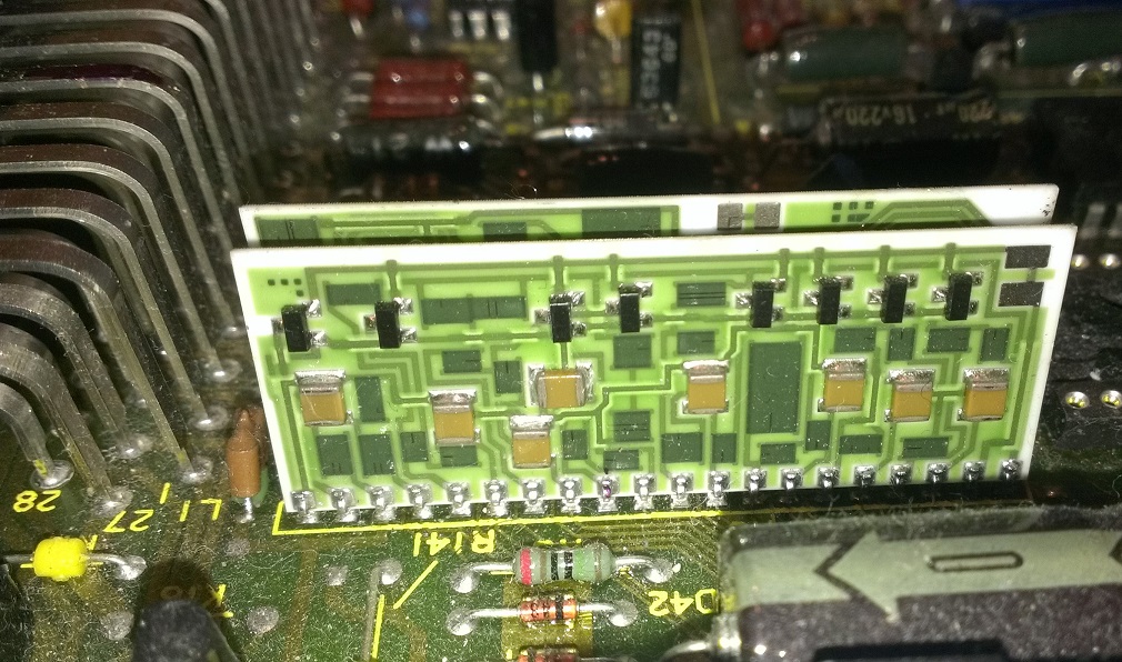
Gassing Station | General TVR Stuff & Gossip | Top of Page | What's New | My Stuff