Tacho driver wiring diagram
Discussion


Guys,
Trying to get my head around the Megajolt wiring....
I have the tacho driver which takes the four coils feed and produces a single signal.
I guess this output should be wired to the ECU pin 1 and tacho line (normally connected to -Ve)
But what shall I do with the resistors on the ECU line?
Are they still needed?
Thanks
I'm not an electrics/electronics wizz but I believe the resistor is to protect the ECU from pure 12v or spikes that may occur at the coil.
Again my understanding is that you get about a 0.7 volt drop across a diode so by the time each pulse has passed through 3 diodes I expect it will do about the same job as the resistor.
Sits back and waits to be flamed.
Steve
Again my understanding is that you get about a 0.7 volt drop across a diode so by the time each pulse has passed through 3 diodes I expect it will do about the same job as the resistor.
Sits back and waits to be flamed.
Steve
Yes you're right. The resistor is here to protect the ECU.
If I add the tacho driver to the resistor, will that not be too much a reduction in the voltage drop going to the ECU and tacho?
I just can't seem to find a valid answer to that question.....
And the coil packs are not better in terms of voltage spike, are they?
If I add the tacho driver to the resistor, will that not be too much a reduction in the voltage drop going to the ECU and tacho?
I just can't seem to find a valid answer to that question.....
And the coil packs are not better in terms of voltage spike, are they?

Sardonicus said:
You need the resistor to protect the Lucas ECU  but I can tell you straight out running both coil - low tension wires into diodes to run the TVR tacho will be crap the needle will swing all around the place you need to condition that circuit
The 4 into 2 into 1 diode circuit has been used in V8 Megasquirt installs for a long time. but I can tell you straight out running both coil - low tension wires into diodes to run the TVR tacho will be crap the needle will swing all around the place you need to condition that circuit What is different about the TVR speedo that would make it not work?
There are quite a few TVR Megasquirt installs so what have they done?
Steve
Steve_D said:
The 4 into 2 into 1 diode circuit has been used in V8 Megasquirt installs for a long time.
What is different about the TVR speedo that would make it not work?
There are quite a few TVR Megasquirt installs so what have they done?
Steve
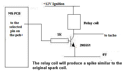
Hi Steve the needle waves all over the show you need a small circuit using a relays coil windings amongst other components to remove the spikes from the switching signal What is different about the TVR speedo that would make it not work?
There are quite a few TVR Megasquirt installs so what have they done?
Steve
 I know the diodes trick alone works with many tacho's it dont with the TVR Caerbont instrument well not correctly anyways
  every Chimaera and Griffith running MS installs I know of run with this box of tricks
 Sardonicus said:
Steve_D said:
The 4 into 2 into 1 diode circuit has been used in V8 Megasquirt installs for a long time.
What is different about the TVR speedo that would make it not work?
There are quite a few TVR Megasquirt installs so what have they done?
Steve
Hi Steve the needle waves all over the show you need a small circuit using a relays coil windings amongst other components to remove the spikes from the switching signal What is different about the TVR speedo that would make it not work?
There are quite a few TVR Megasquirt installs so what have they done?
Steve
I know the diodes trick alone works with many tacho's it dont with the TVR Caerbont instrument well not correctly anyways every Chimaera and Griffith running MS installs I know of run with this box of tricks Steve

So, if I understand correctly, the four into two into one connects with the -Ve for each coil and the single wire then goes to the ECU and Tacho connection.
On my loom I have two thermistors, one for the ECU and one for the tacho.
Instead of tracing each wire to its source, is there a way to know where goes which wire?
On my loom I have two thermistors, one for the ECU and one for the tacho.
Instead of tracing each wire to its source, is there a way to know where goes which wire?
Gassing Station | General TVR Stuff & Gossip | Top of Page | What's New | My Stuff