Calling Max_Torque - manifolds and turbos question
Discussion


Hi All,
I'm hoping (as title) to attract some comment from Mr.Max_torque on a few questions I have, in my opinion it's not often you find someone with the skill and knowledge that Max has that openly gives comment and advice.
So, if you don't mind Max
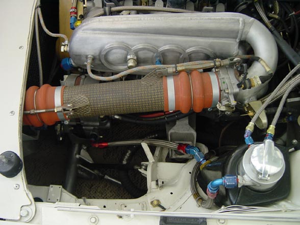
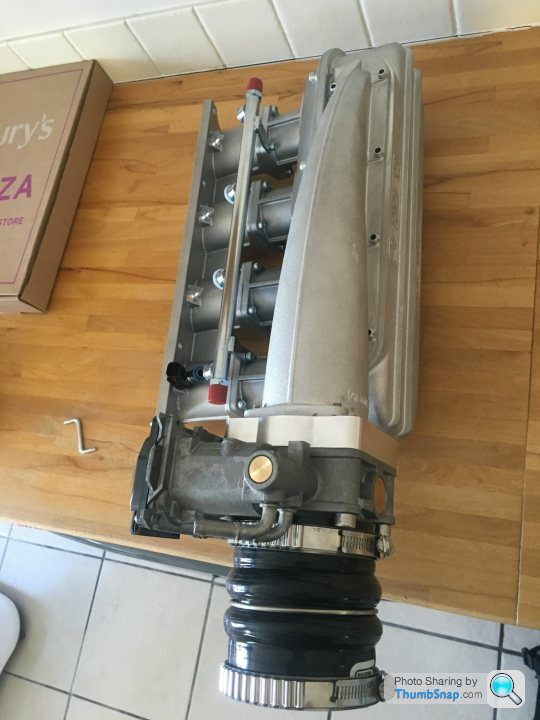
1. Inlet manifold design for a turbocharged engine, I notice your Seat has what appears to be a "dual plenum" inlet manifold with a smaller tapered plenum feeding a larger main plenum. I'm aiming to use a similar manifold on my project (a turbocharged Honda K24 block with K20 head), what is your opinion on the Jenvey Turbo plenum? It's the best option I can find "off the shelf" for my engine but the shape does not look optimal.
2. Any advice on inlet manifold runner length for the above?
3. I am trying to find information on designing the exhuast manilfold, many people I speak to say "doesn't matter on a turbocharged engine" which I disagree with. Can you help or give me some pointers on runner length, or some good reading on the subject? I will be designing this with good wastegate positioning as a priority, something that appears to be overlooked in 99% of after market manifolds.
Any reply, comment or suggestions much appreciated!
Thanks,
A
I'm hoping (as title) to attract some comment from Mr.Max_torque on a few questions I have, in my opinion it's not often you find someone with the skill and knowledge that Max has that openly gives comment and advice.
So, if you don't mind Max
1. Inlet manifold design for a turbocharged engine, I notice your Seat has what appears to be a "dual plenum" inlet manifold with a smaller tapered plenum feeding a larger main plenum. I'm aiming to use a similar manifold on my project (a turbocharged Honda K24 block with K20 head), what is your opinion on the Jenvey Turbo plenum? It's the best option I can find "off the shelf" for my engine but the shape does not look optimal.
2. Any advice on inlet manifold runner length for the above?
3. I am trying to find information on designing the exhuast manilfold, many people I speak to say "doesn't matter on a turbocharged engine" which I disagree with. Can you help or give me some pointers on runner length, or some good reading on the subject? I will be designing this with good wastegate positioning as a priority, something that appears to be overlooked in 99% of after market manifolds.
Any reply, comment or suggestions much appreciated!
Thanks,
A
I'm running a chevy v8 and originally selected a large single plane carb plenum which is aimed at drag racing (so wide open throttle from the off) as it was easier to machine for fuel injectors. Was also told manifold design doesn't matter due to turbo - but I found that it does make a difference. I swapped it for a dual-plane manifold which is what you would use n/a on my engine/car combo (heavy 4x4) and it sorted the problem.
So my view is select the manifold based on the n/a characteristics you desire. Which is essentially long thin runners for low down torque or large short runners for less torque but higher revs.
So my view is select the manifold based on the n/a characteristics you desire. Which is essentially long thin runners for low down torque or large short runners for less torque but higher revs.
eliot said:
I swapped it for a dual-plane manifold which is what you would use n/a on my engine/car combo (heavy 4x4) and it sorted the problem.
But what was the problem?I agree with what you say and using the original inlet is probably the best way to go on a Honda as they will have got it pretty good from the factory, you can maybe hack the plenum off and put a different/bigger one on, but there isn't much to be had in the grand scheme of things, they are at the 'Law of diminishing returns' end of the scale.
You size your parts as per what you want out of it (bhp, power range) which hasn't been supplied.
Shorter exhaust manifolds tend to be favoured by low to mid range power bands, long ones with maybe larger IDs are for more high rpm and extreme power outputs.
In order to get it precisely correct you need to have very intimate knowledge of your engine, most people haven't a clue so just bolt on whatever is on the shelf and hope for the best.
sl0wlane said:
Hi All,
I'm hoping (as title) to attract some comment from Mr.Max_torque on a few questions I have, in my opinion it's not often you find someone with the skill and knowledge that Max has that openly gives comment and advice.
So, if you don't mind Max
1. Inlet manifold design for a turbocharged engine, I notice your Seat has what appears to be a "dual plenum" inlet manifold with a smaller tapered plenum feeding a larger main plenum. I'm aiming to use a similar manifold on my project (a turbocharged Honda K24 block with K20 head), what is your opinion on the Jenvey Turbo plenum? It's the best option I can find "off the shelf" for my engine but the shape does not look optimal.
2. Any advice on inlet manifold runner length for the above?
3. I am trying to find information on designing the exhuast manilfold, many people I speak to say "doesn't matter on a turbocharged engine" which I disagree with. Can you help or give me some pointers on runner length, or some good reading on the subject? I will be designing this with good wastegate positioning as a priority, something that appears to be overlooked in 99% of after market manifolds.
Any reply, comment or suggestions much appreciated!
Thanks,
A
At a guess you're overthinking things. How much power are you aiming for ? Are you pushing extremes ?I'm hoping (as title) to attract some comment from Mr.Max_torque on a few questions I have, in my opinion it's not often you find someone with the skill and knowledge that Max has that openly gives comment and advice.
So, if you don't mind Max
1. Inlet manifold design for a turbocharged engine, I notice your Seat has what appears to be a "dual plenum" inlet manifold with a smaller tapered plenum feeding a larger main plenum. I'm aiming to use a similar manifold on my project (a turbocharged Honda K24 block with K20 head), what is your opinion on the Jenvey Turbo plenum? It's the best option I can find "off the shelf" for my engine but the shape does not look optimal.
2. Any advice on inlet manifold runner length for the above?
3. I am trying to find information on designing the exhuast manilfold, many people I speak to say "doesn't matter on a turbocharged engine" which I disagree with. Can you help or give me some pointers on runner length, or some good reading on the subject? I will be designing this with good wastegate positioning as a priority, something that appears to be overlooked in 99% of after market manifolds.
Any reply, comment or suggestions much appreciated!
Thanks,
A
If you're getting picky about exhaust manifold design..of course head design, intake, cam profiles, exhaust, turbo etc all then need to be factored in as a package.
What is the engine used for, over what rpm range etc etc
As for saying wastegate position is overlooked.....no doubt it is placed where it is practical given physical constraints...and you can be fairly sure in 98% of cases it works perfectly fine. So in many respects it is the least of the worries
IMO, keep it simple its a doddle to make power with a turbo engine.
Edited by stevieturbo on Monday 25th July 11:44
stevieturbo said:
At a guess you're overthinking things. How much power are you aiming for ? Are you pushing extremes ?
If you're getting picky about exhaust manifold design..of course head design, intake, cam profiles, exhaust, turbo etc all then need to be factored in as a package.
What is the engine used for, over what rpm range etc etc
As for saying wastegate position is overlooked.....no doubt it is placed where it is practical given physical constraints...and you can be fairly sure in 98% of cases it works perfectly fine. So in many respects it is the least of the worries
IMO, keep it simple its a doddle to make power with a turbo engine.
I dont think I'm over thinking anything, I want to make the best possible power / get the best result, but most of all LEARN from the experience so I understand the result I get.If you're getting picky about exhaust manifold design..of course head design, intake, cam profiles, exhaust, turbo etc all then need to be factored in as a package.
What is the engine used for, over what rpm range etc etc
As for saying wastegate position is overlooked.....no doubt it is placed where it is practical given physical constraints...and you can be fairly sure in 98% of cases it works perfectly fine. So in many respects it is the least of the worries
IMO, keep it simple its a doddle to make power with a turbo engine.
Edited by stevieturbo on Monday 25th July 11:44
Aiming for... ~500+whp (so not record breaking, but still a good 200bhp+ per liter), engine will be used in a Lotus Elise/Exige chassis for track work, with a Quaife sequential, rev limit of ~8000rpm (piston speeds taken into account).
I am lucky as I am not too constrained in packaging of the exhaust manifold - plenty of room for optimised length and construction - so I am looking for guidance on choosing / designing the optimal solution.
Edited by sl0wlane on Monday 25th July 14:49
the reason a side entry plenum for a forced induction inline 4 engine is tapered is to maintain a constant air velocity across all four cylinders.
As each cylinder takes its breath, the air mass is reduced by 25%. To maintain air speed and with it pressure equal across all cylinders, the cross section reduces by 25% over each cylinder. Cyl 1 100%, Cyl 2 75%, 3 50%, 4 25%. For a Na engine, this effect is much less pronounced, hence NA a plenum often uses a uniform cross section.
if you use a NA uniform cross sectioned side entry plenum with reasonably high boost, say 7 PSI and higher, the first cylinder will run leaner than average and the last one richer than average.
you can use individual cylinder trimming to correct for this, but it would require 4 EGT probes or better 4 wideband probes, one for each cylinder.
The dual plenum designs work in a similar manner. The small inlet plenum tapered as above. It is connected to the main plenum with a longitudinal slit across the entire length of the tapered part.. Due to providing uniform pressure and velocity across the slit, the bigger secondary plenum is filled uniformly across all cylinders through that slit The larger total volume of the uniform plenum helps reducing pressure fluctuations thereby increasing air flow.
Here are some examples and a useful discussion:
http://www.k20a.org/forum/showthread.php?t=90664
The length and cross section of the intake runners primarily determine the range of peak torque. The length is primarily acting through acoustic resonance. The cross section is more modulating air velocity.
Small cross sections provide high air velocity at low rpm lowering the rpm of peak torque.
Long runners resonate at low frequencies, shorter at high frequencies.
When it comes to forced induction, the same acoustic principles apply. What makes life easy is that the speed of sound does not change much with air pressure. As pressure increases, the density increase would increase speed of sound, but the increased air mass reduces it again. So for the sake of the accuracy empirical formulas used to calculate plenum runner length and cars section, you can treat speed of sound as constant or can ignore the pressure.
The first thing you need is to determine at what power band your engine should have. the second boundary condition is often packaging.
Edited by Ive on Monday 25th July 15:18
Edited by Ive on Monday 25th July 15:20
Edited by Ive on Monday 25th July 15:20
what turbo?
Twin scroll or open scroll exhaust manifold?
I`m sure you`re not re inventing the wheel on this build so what has been done previously?
Jenvey plenum will work and has been proven to flow well north of 500whp.
At your power level and high rpm I would go twin scroll possibly Borg Warner EFR 7670
Speak to James at Nortech Performance. He custom made a lovely twin scroll manifold for my YB Westfield project.
Edited by jontysafe on Monday 25th July 15:34
Edited by jontysafe on Monday 25th July 15:36
Ive said:
the reason a side entry plenum for a forced induction inline 4 engine is tapered is to maintain a constant air velocity across all four cylinders.
As each cylinder takes its breath, the air mass is reduced by 25%. To maintain air speed and with it pressure equal across all cylinders, the cross section reduces by 25% over each cylinder. Cyl 1 100%, Cyl 2 75%, 3 50%, 4 25%. For a Na engine, this effect is much less pronounced, hence NA a plenum often uses a uniform cross section.
The dual plenum designs work in a similar manner. The small inlet plenum tapered as above. It is connected to the main plenum with a longitudinal slit across the entire length of the tapered part.. Due to providing uniform pressure and velocity across the slit, the bigger secondary plenum is filled uniformly across all cylinders through that slit The larger total volume of the uniform plenum helps reducing pressure fluctuations thereby increasing air flow.
Here are some examples and a useful discussion:
http://www.k20a.org/forum/showthread.php?t=90664
Thanks Ive - and yes, fully understand the function of the "dual" plenum - notice my post is the last on the thread you linked As each cylinder takes its breath, the air mass is reduced by 25%. To maintain air speed and with it pressure equal across all cylinders, the cross section reduces by 25% over each cylinder. Cyl 1 100%, Cyl 2 75%, 3 50%, 4 25%. For a Na engine, this effect is much less pronounced, hence NA a plenum often uses a uniform cross section.
The dual plenum designs work in a similar manner. The small inlet plenum tapered as above. It is connected to the main plenum with a longitudinal slit across the entire length of the tapered part.. Due to providing uniform pressure and velocity across the slit, the bigger secondary plenum is filled uniformly across all cylinders through that slit The larger total volume of the uniform plenum helps reducing pressure fluctuations thereby increasing air flow.
Here are some examples and a useful discussion:
http://www.k20a.org/forum/showthread.php?t=90664
Ive said:
The length and cross section of the intake runners primarily determine the range of peak torque. The length is primarily acting through acoustic resonance. The cross section is more modulating air velocity.
Small cross sections provide high air velocity at low rpm lowering the rpm of peak torque.
Long runners resonate at low frequencies, shorter at high frequencies.
When it comes to forced induction, the same acoustic principles apply. What makes life easy is that the speed of sound does not change much with air pressure. As pressure increases, the density increase would increase speed of sound, but the increased air mass reduces it again. So for the sake of the accuracy empirical formulas used to calculate plenum runner length and cars section, you can treat speed of sound as constant or can ignore the pressure.
Thanks - I can apply this and compare my runner length to the results from others.Small cross sections provide high air velocity at low rpm lowering the rpm of peak torque.
Long runners resonate at low frequencies, shorter at high frequencies.
When it comes to forced induction, the same acoustic principles apply. What makes life easy is that the speed of sound does not change much with air pressure. As pressure increases, the density increase would increase speed of sound, but the increased air mass reduces it again. So for the sake of the accuracy empirical formulas used to calculate plenum runner length and cars section, you can treat speed of sound as constant or can ignore the pressure.
I'm aiming for a usable powerband 4000rpm through 8000rpm
Edited by sl0wlane on Monday 25th July 15:30
Edited by sl0wlane on Monday 25th July 15:30
sl0wlane said:
I dont think I'm over thinking anything, I want to make the best possible power / get the best result, but most of all LEARN from the experience so I understand the result I get.
Aiming for... ~500+whp (so not record breaking, but still a good 200bhp+ per liter), engine will be used in a Lotus Elise/Exige chassis for track work, with a Quaife sequential, rev limit of ~8000rpm (piston speeds taken into account).
I am lucky as I am not too constrained in packaging of the exhaust manifold - plenty of room for optimised length and construction - so I am looking for guidance on choosing / designing the optimal solution.
Keep tubes small, short, go proper twin scroll. As said, keep it simple. 500hp is a pretty easy goal to achieve even more so with modern turbochargers etc. Design doesnt need to need to be anything fancy or complicated at all.Aiming for... ~500+whp (so not record breaking, but still a good 200bhp+ per liter), engine will be used in a Lotus Elise/Exige chassis for track work, with a Quaife sequential, rev limit of ~8000rpm (piston speeds taken into account).
I am lucky as I am not too constrained in packaging of the exhaust manifold - plenty of room for optimised length and construction - so I am looking for guidance on choosing / designing the optimal solution.
Edited by sl0wlane on Monday 25th July 14:49
IMO make it so it fits and can be worked around easier as a priority rather than making it a nightmare that may affect reliability etc.
As 500+ is a little vague....is that like 501 or 6, 7, 800 ? I'd nearly say go for the likes of the smaller EFR 7064 or 7163 especially as it's a light vehicle.

From what I've read on passionford the Jenvey manifold gets mixed reviews and there's a Finnish guy offering custom dual plenum inlets for less that are stronger in construction. I had his email but I can't find it now sorry.
Look at what Porsche did with it's turbo intake design, it basically works opposite to NA design, lengths and shapes act to "decompress" the charge (opposite of ramming effect) to get an additional cooling effect. It's a bit of unconventional thinking as usually one designs the engine to maximise VE in the same range as boost threshold as that helps spool.
The exhaust design seems to benefit more from proper shapes than lengths until you're into extreme territory - i.e nice smooth transitions, minimal bends and well constructed merges.
It might not matter much until you're really pushing things but it does matter to keep as much dynamism and energy in the exhaust gasses, and not have them fighting each other.
Getting the bore size right will also be critical to spool, and you at least have a power figure in mind so hopefully someone will give you some hard numbers there but they're smaller than seems intuitive imo.
Well I have found a few more resources online, looks like I need further info on the cam spec... Which I have most of but cam centre line is proving harder to pin down... as its a VTEC engine and also fitted with an adjustable exhaust pulley...
Anyone got a really good model of a turbo K20 in GTSuite they don't mind sharing? (unlikely, I understand it takes months to build an accurate model).
Anyone got a really good model of a turbo K20 in GTSuite they don't mind sharing?
(unlikely, I understand it takes months to build an accurate model).There is but only on Seloc... I might copy over here too at some point (Seloc being locked out for even viewing unless registered is a bit of a pain).
A basic run down of the spec sheet:
Clockwise Motion Darton sleeved K24 87x99mm block
K20a head (ported exhaust ports, standard intake).
Inconel exhaust valves
K20 oil pump etc (standard k20/24 frank setup)
Clockwise "turbo" cams and adjustable exhaust pulley
Clockwise forged steel con rods
CP 9.5:1 forged pistons
L19 head studs
Clockwise ultralight flywheel & twin plate clutch
Clockwise baffled sump
Clockwise water pump delete and lightweight alternator kit (will use the BMW cWA200 electric pump)
Laminova oil cooler (the biggest one)
Jenvey turbo plenum and inlet manifold
70mm flybywire throttle body
ID1000 injectors
DW 300 fuel pump
DW fuel pressure regulator
TiAL 44 mvr wastegate
Owen developments ODGT3579HTA M-spec turbo
Quaife sequential box with LSD
ECU is a an EFI Euro4 from Ole Buhl, which has traction control, closed loop boost, ETB control, closed loop flat shift, closed loop fuel etc etc etc
The project is with Dan Webster at HPE
Still working out how to do intercooling and exhaust (no, I'm not doing a charge-cooler! I'm going air-air)
Umm that's about all the relivent bits I think.
Edited by sl0wlane on Thursday 18th August 23:34
Edited by sl0wlane on Thursday 18th August 23:37
in general a plenum should have a certain minimum volume that is usually a multiple of each cylinders displacement.
I remeber it being like 10x to avoid power losses from pressure drop in the chamber as the intake stroke happens.
so for a 2.4l your want some 6 liters inthe ideal world. in reality you get away with much less before significan losses occur.
My old KTM Duke 2nd edition came with a tiny airbox from the factory. 609cc single attached to a like 2l airbox is no good. Increasing plenum volume to infinite by fitting a open air filter. no other changes than a bigger mainjet released plenty of top end power.
The length is entirely dependent of the rpm band. I have sned you the spread sheet with some empirical fomulas in it.
you need cross section and lengh from mouth to intake valve. Then check where the 2nd, 3rd and 4th harmonics are.
if you strive for 7000 rpm peak torque, you want your effective lengh tuned to the 2nd or 3rd harmonic at that rpm. 1st would even be better, but I doubt you can and want to fit such long snorkel to your engine.
My old plastic plenum on my supercharged K would really pick up again past 7800 rpm. This fitted to the 4th harmonic of this geometry. In between 5000 rpm of the 3rd harmonic peak and the 7800 of the 4th there is the "valley of death". here the refelcting sound waves actually reduce the pressure at the port during the intake stroke. You could feel it and see it from the fuel values to maintain AFR and from the ignition timing I could add before knock. VE was dropping.
The shorter VVC plenum shifts things upward, so I am less affected by the drop past the 3rd harmonic peak. Still, past 7000, power does not rise anymore as VE drops.
If I would fit ITBs with shorter runners than the VVC plenum, VE would drastically increase at high revs. This can be seen from dyno data. otherwise identical spec NA engines,m even the same cam timing, generate some 160HP on a plenum at 7000 and some 180HP on ITBs.
have you calculated the peak rpms for your intake set-up? what length is the intake path from mouth to intake valve? What is the (average if conical) cross section?
The only reason the Honda k20 engines get away with such a short plenum regarding the low and mid rpm torque is their reduced cam timing and lift to help VE in those load and rpm ranges. At the top they need the short wide runners to be able fill the cylinders effecitvely.
if you check some online articles comapring various plenums on K20 engines with dyno charts, you can nicely see the influence of the length of torque and power. as this influence is large pressure independent, you can orient yourself on thos lenghts regardng your intended torque curve.
Edited by Ive on Friday 19th August 12:18
Gassing Station | Engines & Drivetrain | Top of Page | What's New | My Stuff