Project Scimitar MV6
Discussion


Another slow day today, I'm not sure whats wrong with me, I wasn't really feeling it today, but I got some things done.
I put the ali tube in the vice and put a flat on it, then drilled it and put a screw in type car tire valve. I could use this as s manual bleed or a plumbed in one with the valve removed.
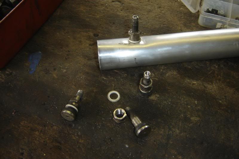
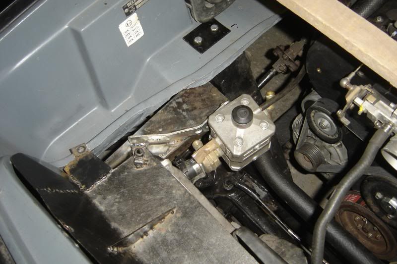
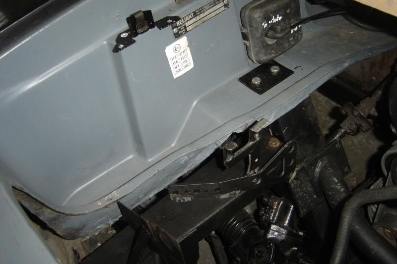
I also mounted the little vacuum reservoir just below the very foward most part of the master cylinder, I'm quite pleased with how this looks. The paddle in the plenum is vacuum opporated so needs this reservoir so it can work under full throttle (i.e. no vacuum in the manifold).
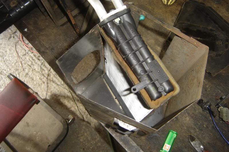
And the last little job I did was to mount the LPG vaporiser,
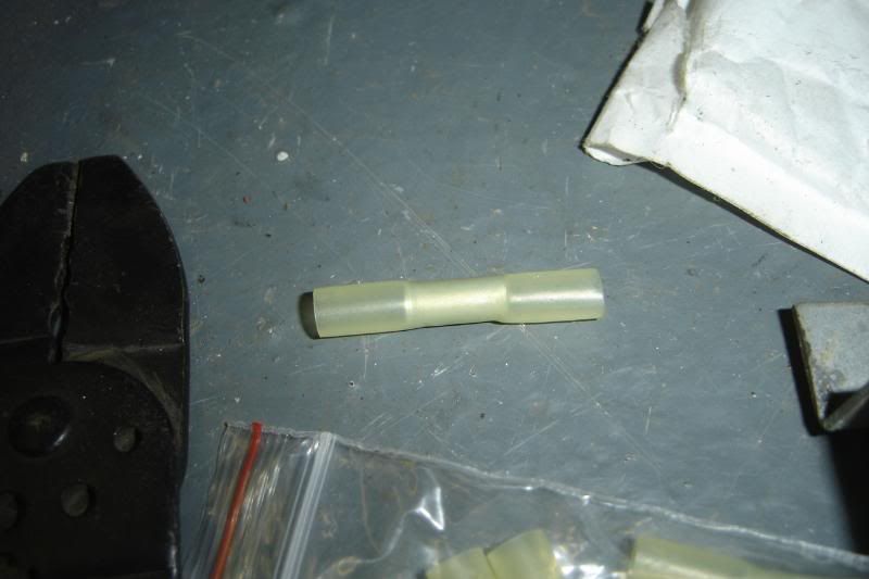
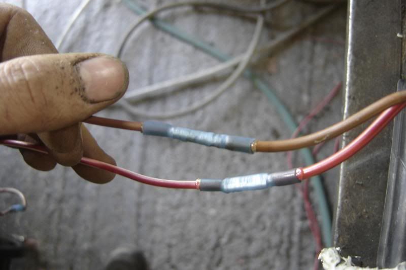
After some comments on the PPC forum I've decided to use shrink wrapped butt crimps on the loom, I've even bought an expensive crimping tool to do the job with.
More to come (hopefully some actually progress tomorrow)
I put the ali tube in the vice and put a flat on it, then drilled it and put a screw in type car tire valve. I could use this as s manual bleed or a plumbed in one with the valve removed.
I also mounted the little vacuum reservoir just below the very foward most part of the master cylinder, I'm quite pleased with how this looks. The paddle in the plenum is vacuum opporated so needs this reservoir so it can work under full throttle (i.e. no vacuum in the manifold).
And the last little job I did was to mount the LPG vaporiser,
After some comments on the PPC forum I've decided to use shrink wrapped butt crimps on the loom, I've even bought an expensive crimping tool to do the job with.
More to come (hopefully some actually progress tomorrow)
I had a good day today, not got a huge amount done, but loads of thinking and I'm pleased with how its all going. I put in lots of effort, but the real steps forward will be tomorrow when it all goes together, I'm hoping to have the fan in, the bumper on, the nose supports in, the radiator in, the expainsion tank in, the vaporiser in and all the cooling system plumbed in ready to go. Then If time I can start on mounting the LPG injectors safely, and perhaps even make a start on either the loom of the exhaust manifolds, but lets be honest that might be what I get done this summer.
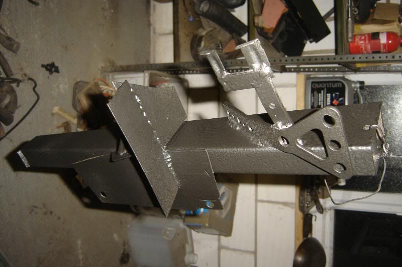
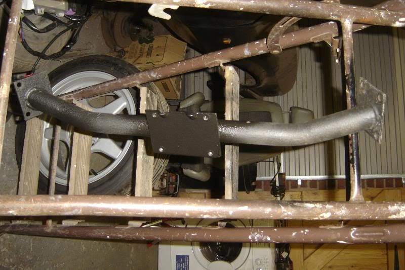
I cut off the omega expansion tank mounts from the car shell and adapted them to fit the Scim, this is the lower of the two mounts now welded to the right side nose support with the vaporiser mounted welded on too, and its now all painted in stone chip.
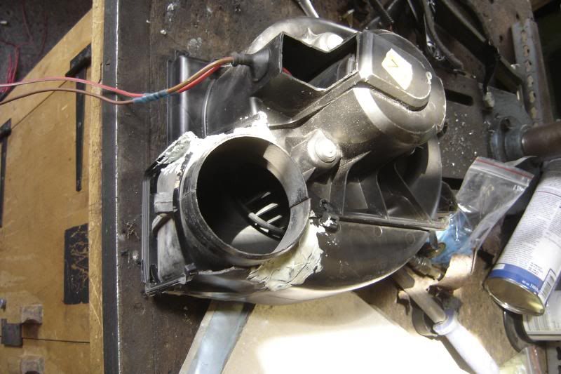
This means there is very little stopping me putting the front back together perminantly, except the fans. I wanted these to be better than a mouse sneezing like the Scim originals, and what is free and sitting on the drive, an omega blower. Its a beast, it has to blow through a bit AC radiator and reach the ducting through to the rear of the car. So out it came. What followed was hours of um-ing and ah-ing but. Long story short, it'll sit in the left side where one of the originals used to sit and take its air from the space infront of the radiator. I'm going to simplify the heating system (even more). It'll either blow hot air on the windscreen and your feet, or it'll blow cold though the outer most vents, thats it, the central consol vents are going and the number of controls will be reduced. I'm also going to do my best to get the mych better looking omega heater matrix to fit whats left of the scimitar heater box, its almost the right shape
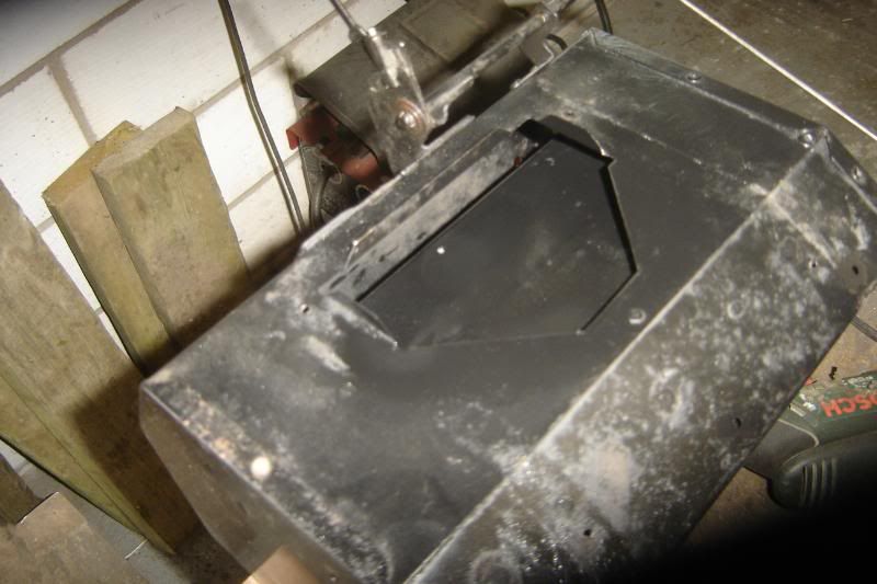
Here's the fan motor half way through being butchered
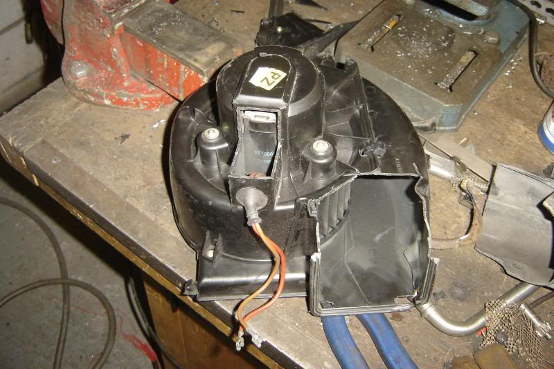
And with a bit of the old smiths motor grafted on, it works a treat, it blows a gail into the car (not yet finished here).
I'll block off the other inlet down the drivers wing, its plenty powerful enough with this motor.
Annoyingly the camera ran out of battery. I'll take more photos tomorrow, and try to do a better job explaining the heater modifications.
More to come.
PS, the engineering is finally doing the last hub I've been bothering him about it for a while now and he called me tonight at 9 as he was starting the job, I feel kinda bad about it now
I cut off the omega expansion tank mounts from the car shell and adapted them to fit the Scim, this is the lower of the two mounts now welded to the right side nose support with the vaporiser mounted welded on too, and its now all painted in stone chip.
This means there is very little stopping me putting the front back together perminantly, except the fans. I wanted these to be better than a mouse sneezing like the Scim originals, and what is free and sitting on the drive, an omega blower. Its a beast, it has to blow through a bit AC radiator and reach the ducting through to the rear of the car. So out it came. What followed was hours of um-ing and ah-ing but. Long story short, it'll sit in the left side where one of the originals used to sit and take its air from the space infront of the radiator. I'm going to simplify the heating system (even more). It'll either blow hot air on the windscreen and your feet, or it'll blow cold though the outer most vents, thats it, the central consol vents are going and the number of controls will be reduced. I'm also going to do my best to get the mych better looking omega heater matrix to fit whats left of the scimitar heater box, its almost the right shape
Here's the fan motor half way through being butchered
And with a bit of the old smiths motor grafted on, it works a treat, it blows a gail into the car (not yet finished here).
I'll block off the other inlet down the drivers wing, its plenty powerful enough with this motor.
Annoyingly the camera ran out of battery. I'll take more photos tomorrow, and try to do a better job explaining the heater modifications.
More to come.
PS, the engineering is finally doing the last hub
I've been bothering him about it for a while now and he called me tonight at 9 as he was starting the job, I feel kinda bad about it now Edited by lozzzzzz on Thursday 18th August 22:45
Today, I wanted to do loads and its not all happened but still a good day I think.
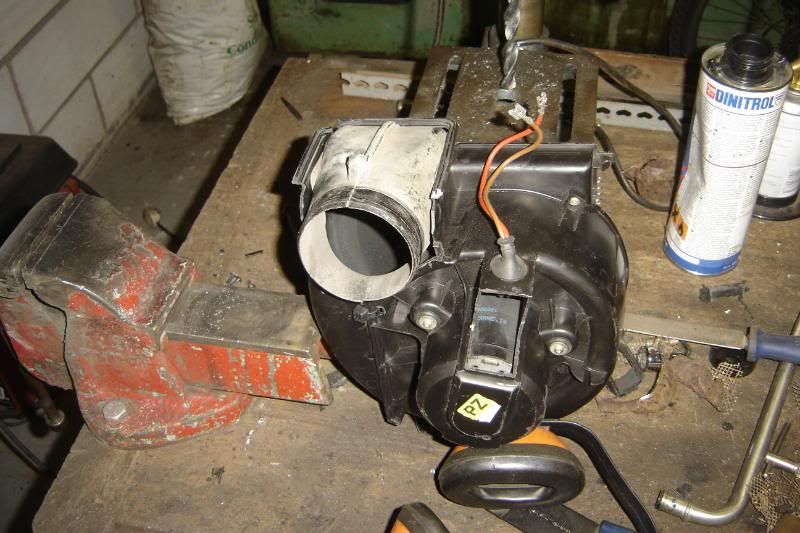
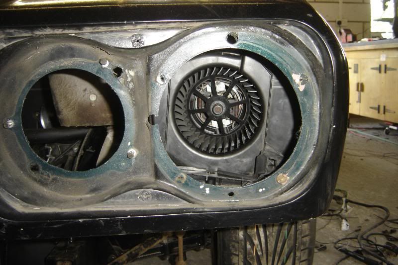
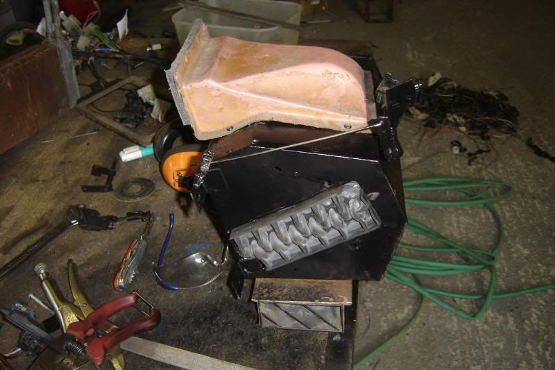
This is the finished fan blower, the only addition being a little filler to block some of the bigger holes. I'm really pleased with how strong this is even before the filler, the single zip tie seems to have clamped the addition in place really tightly.
Its mounted with a shet of SS screwed to the housing through the original blower inlet hole (bumper removed)
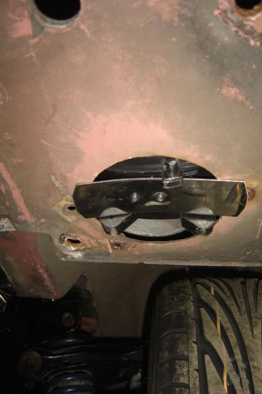
And sits like this inside the front of the car
The shrink wrap butt connectors came in the post today, they're awesome. They take a little longer to shrink than normal shrink wrap but it seems the inside layer has a much lower melting point so as it starts to shrink a sealing glue comes oozing out, completely sealing the connection, highly recommended.
Got the bumper fully fitted today, it took a while with the blower in the way, I should have mounted in such a way that meant it could be fitted with the bumper in situe.
This is the nose braket, with the vaporiser mount and the expansion tank mount in place
Spent the rest of the afternoon on the loom, which is coming along nicely now, until the lighter ran out of the gas
More to come tomorrow
This is the finished fan blower, the only addition being a little filler to block some of the bigger holes. I'm really pleased with how strong this is even before the filler, the single zip tie seems to have clamped the addition in place really tightly.
Its mounted with a shet of SS screwed to the housing through the original blower inlet hole (bumper removed)
And sits like this inside the front of the car
The shrink wrap butt connectors came in the post today, they're awesome. They take a little longer to shrink than normal shrink wrap but it seems the inside layer has a much lower melting point so as it starts to shrink a sealing glue comes oozing out, completely sealing the connection, highly recommended.
Got the bumper fully fitted today, it took a while with the blower in the way, I should have mounted in such a way that meant it could be fitted with the bumper in situe.
This is the nose braket, with the vaporiser mount and the expansion tank mount in place
Spent the rest of the afternoon on the loom, which is coming along nicely now, until the lighter ran out of the gas
More to come tomorrow
Got back from scotland today and did a little in the afternoon.
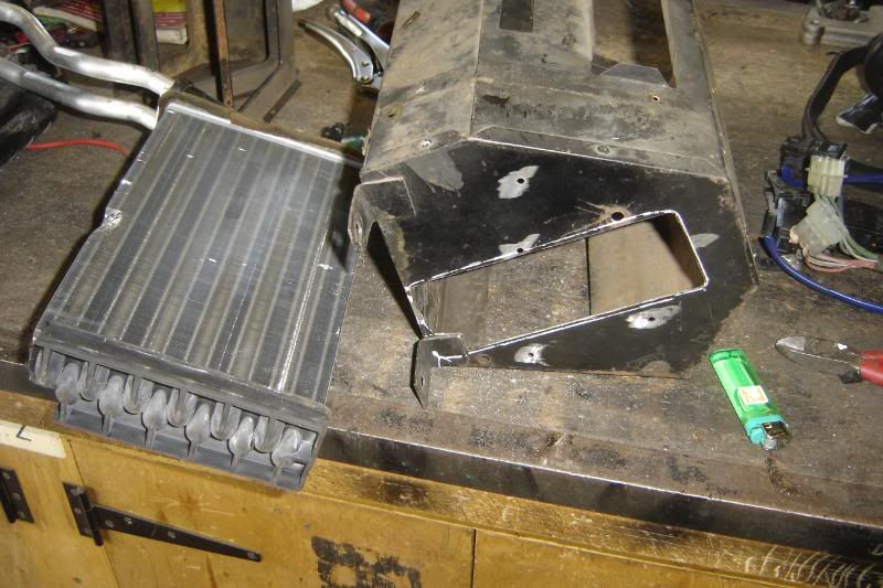
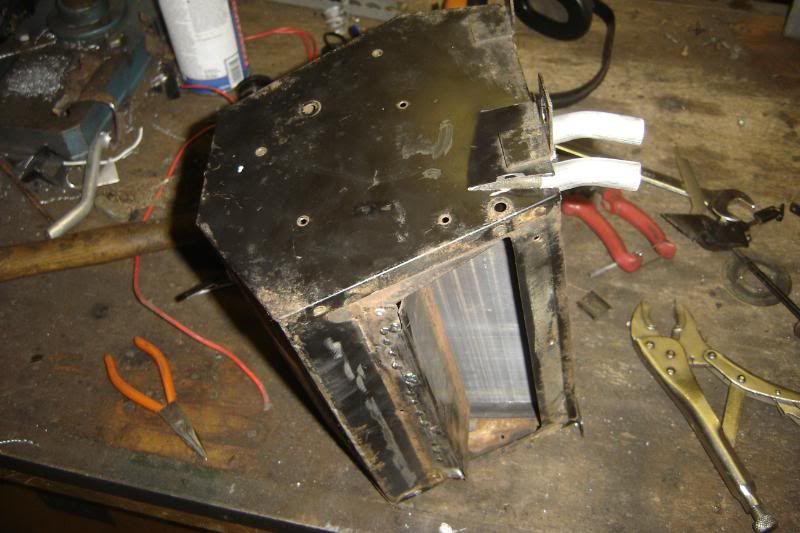
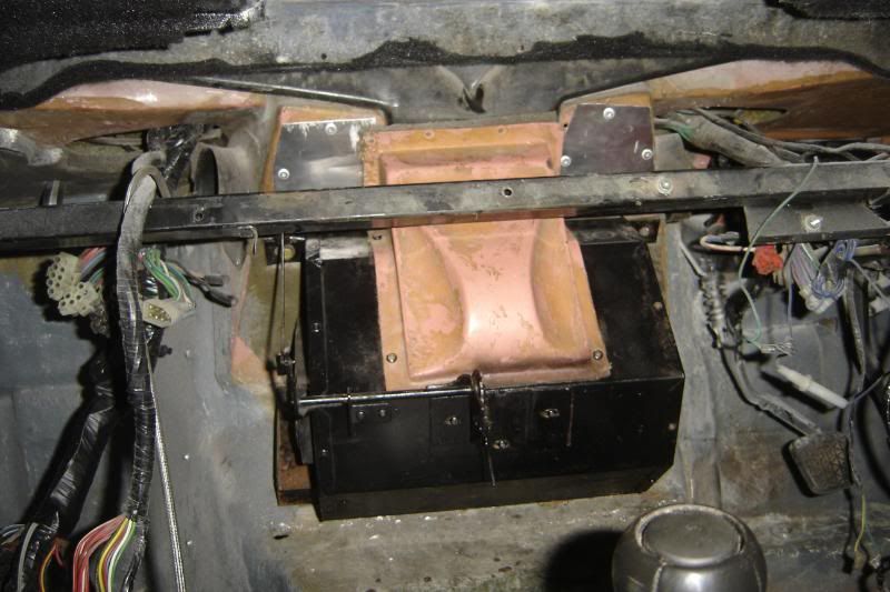
I left the wiring and tried to get the header box how I wanted it. First I cut back all the rivets and took it apart

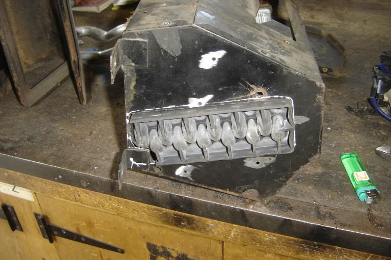
This was nessesary to get the omega heater matrix to fit as its a bit taller and slightly wider.
I was planning on keeping the basic route the air takes the same as before. The larger matrix makes it a little tighter for the air to come back around and head up tot he windscreen vents, but the new blower should get round this to some extent.
I cut a big hole in one side of the heater box to let the matrixs' rubber end to protrude a little making it fit better
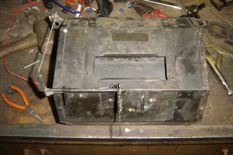
The lower paddle is removed and a section of it welded back in place perminantly to divided the air exiting the matrix, half to the feet and half to the windscreen.
There will only be one control now, this opporates a new paddle that either allows air into the heater box or completely closes it off
At this point the b****y camera batteries gave up again so I'll take a piccie of the inside of the heater box tomorrow and explain what I'm going for.
More to come
I left the wiring and tried to get the header box how I wanted it. First I cut back all the rivets and took it apart
This was nessesary to get the omega heater matrix to fit as its a bit taller and slightly wider.
I was planning on keeping the basic route the air takes the same as before. The larger matrix makes it a little tighter for the air to come back around and head up tot he windscreen vents, but the new blower should get round this to some extent.
I cut a big hole in one side of the heater box to let the matrixs' rubber end to protrude a little making it fit better
The lower paddle is removed and a section of it welded back in place perminantly to divided the air exiting the matrix, half to the feet and half to the windscreen.
There will only be one control now, this opporates a new paddle that either allows air into the heater box or completely closes it off
At this point the b****y camera batteries gave up again so I'll take a piccie of the inside of the heater box tomorrow and explain what I'm going for.
More to come
Had a resonable day at it today, got some boring diesel car stuff done and on a more exciting note I bought the ECU that'll be running the engine, they emailed across the software, its so cool
Took a photo of the inside of the air and put some colourful arrows on it. The cold air enters the box as it used to (Blue arrows) and goes through the matrix as it used to (red and purple arrows). There is now a flat that can be closed (green arrow) to stop any air getting into the heater box at all, this is the only control it will have. You can see that half the hot air will go to the feet area (red arrows) and the other half should go up to the windscreen (purple arrows).
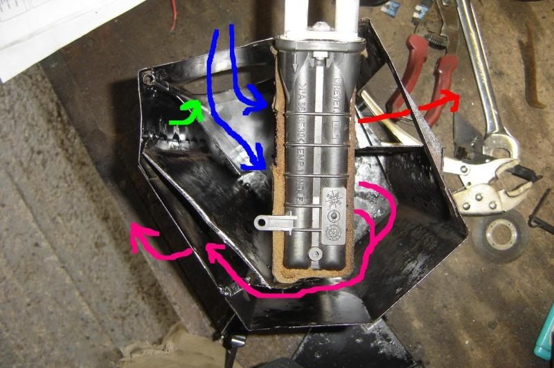
So to heat the car I'll close the outer vents, and open the heater box. To cool it, close the heater box and open the outer vents or windows, The new fan will still have 2 speeds. Simples
I cut the hole a little bigger to help get more air to the windscreen
And the finished and painted (badly) item
The centre vents have been closed off to further simplify the dash and switching.
The hoses to the matrix were connected prior to putting it in as the tails are too short to reach from in the engine bay. I added a load of out hose protection to stop them wearing through where they pass through the bulk head.
The mount holes needed a little "teasedaling" and the matrix hose tails meant it had to mounted 5mm ish further to the left
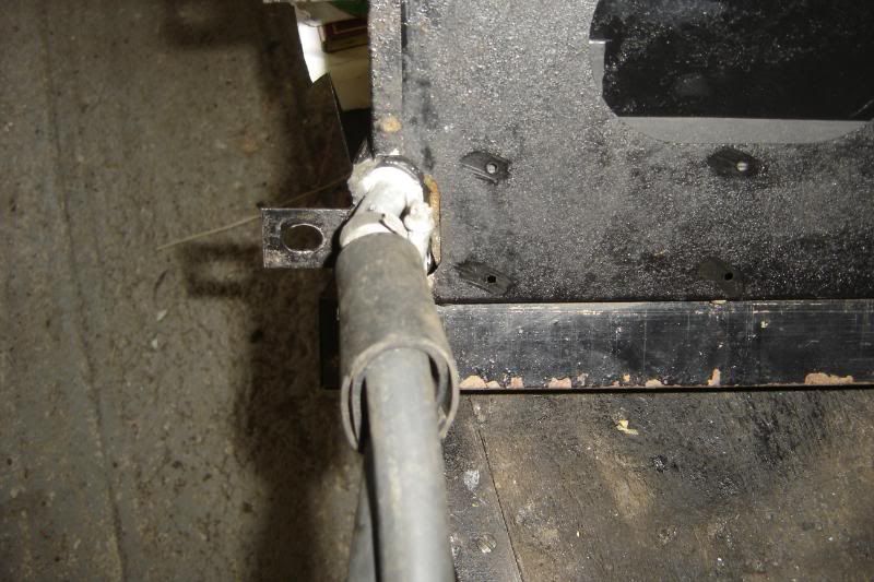
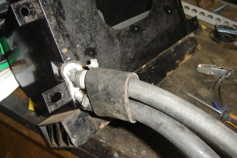
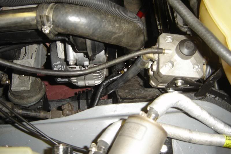
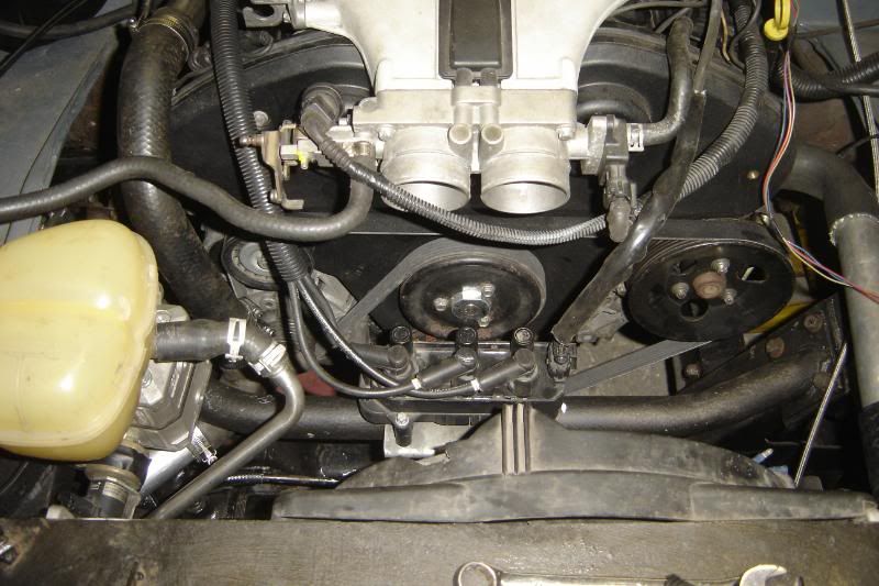
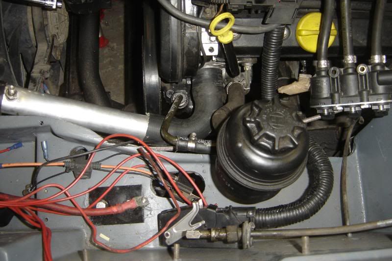
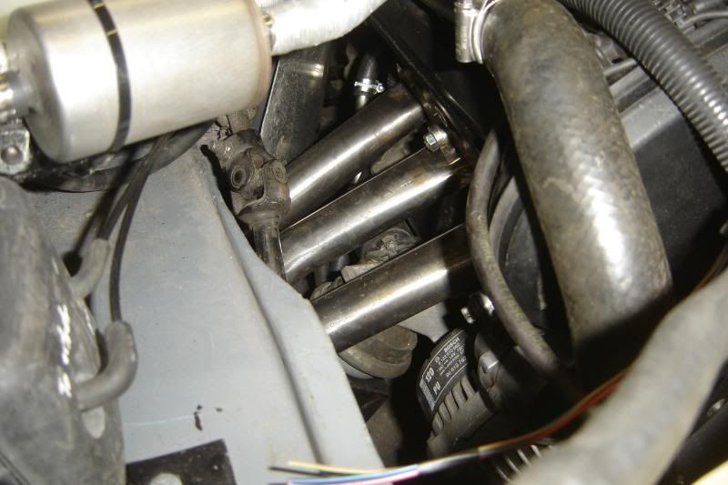
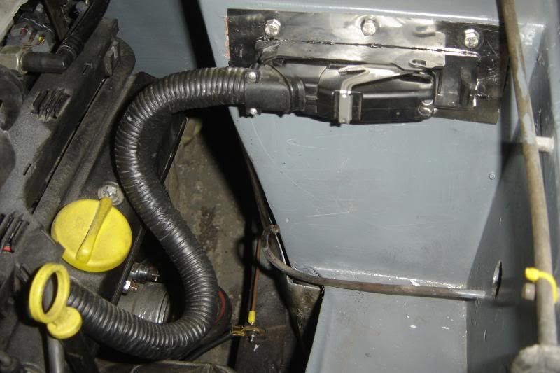
I put another large coolant hose over the two small hoses to the matrix and tied it back to the bulkhead to stop any relative movement between the bulkhead and hoses. and welded a little bracket to the large stainless hose that originates from the back of the engine. So the large hose that'll move with the engine and the smaller hoses that'll be still with the body shouldn't touch each other. The photo makes it looks close but there is about 1cm between them. The bracket mounts at the rear of the cam cover.
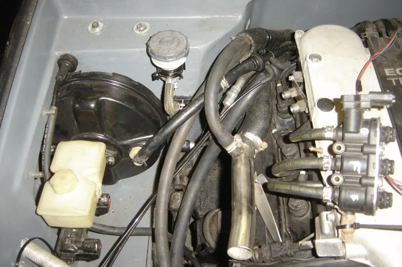
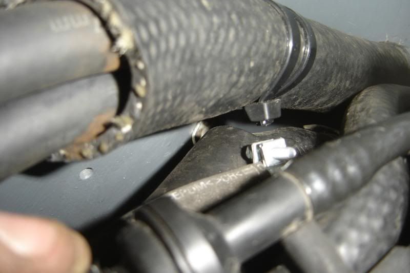
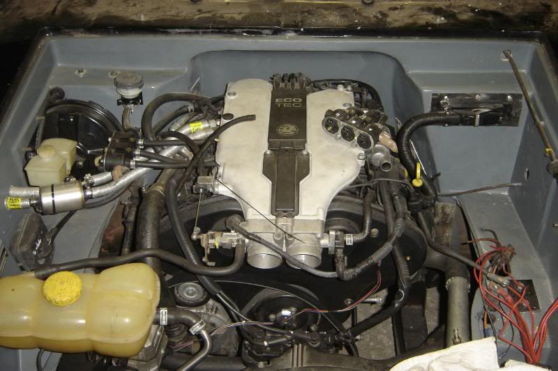
If anyone wants to read more, I'll explain the routing of the hoses. Refer to the second of the three photos above. The large one is the return from the radiator to the back of the engine. I've included the section of SS that came of the omega for tis T piece. The hot water comes from the back of the heads through the small hose that you can see closest the plenum chamber at the top left of the photo, it then passes under the tiny vacuum hoses and heads down to the lower waer connection on the LPG vaporiser. The coolant will then come out the top hose on the vaporiser to the heater matrix (this is the hose that passes closest to the servo). The coolant then come out of the matrix top hose and returns to the T piece in the large SS hose. From here it'll return the engine.
Obviously there is a large coolant hose on the other side of the engine for when the thermostat is open.
Today was a lot of head scratching, so hopefully tomorrow will see more putting back together after I've bought a few jubilees and so on.
More to come
Took a photo of the inside of the air and put some colourful arrows on it. The cold air enters the box as it used to (Blue arrows) and goes through the matrix as it used to (red and purple arrows). There is now a flat that can be closed (green arrow) to stop any air getting into the heater box at all, this is the only control it will have. You can see that half the hot air will go to the feet area (red arrows) and the other half should go up to the windscreen (purple arrows).
So to heat the car I'll close the outer vents, and open the heater box. To cool it, close the heater box and open the outer vents or windows, The new fan will still have 2 speeds. Simples
I cut the hole a little bigger to help get more air to the windscreen
And the finished and painted (badly) item
The centre vents have been closed off to further simplify the dash and switching.
The hoses to the matrix were connected prior to putting it in as the tails are too short to reach from in the engine bay. I added a load of out hose protection to stop them wearing through where they pass through the bulk head.
The mount holes needed a little "teasedaling" and the matrix hose tails meant it had to mounted 5mm ish further to the left
I put another large coolant hose over the two small hoses to the matrix and tied it back to the bulkhead to stop any relative movement between the bulkhead and hoses. and welded a little bracket to the large stainless hose that originates from the back of the engine. So the large hose that'll move with the engine and the smaller hoses that'll be still with the body shouldn't touch each other. The photo makes it looks close but there is about 1cm between them. The bracket mounts at the rear of the cam cover.
If anyone wants to read more, I'll explain the routing of the hoses. Refer to the second of the three photos above. The large one is the return from the radiator to the back of the engine. I've included the section of SS that came of the omega for tis T piece. The hot water comes from the back of the heads through the small hose that you can see closest the plenum chamber at the top left of the photo, it then passes under the tiny vacuum hoses and heads down to the lower waer connection on the LPG vaporiser. The coolant will then come out the top hose on the vaporiser to the heater matrix (this is the hose that passes closest to the servo). The coolant then come out of the matrix top hose and returns to the T piece in the large SS hose. From here it'll return the engine.
Obviously there is a large coolant hose on the other side of the engine for when the thermostat is open.
Today was a lot of head scratching, so hopefully tomorrow will see more putting back together after I've bought a few jubilees and so on.
More to come
I think I got on fairly well today, I've lowered my expectations of what I can get through in a day as I do work really slowly, I must literally take half the time, looking and thinking it through, anyway.
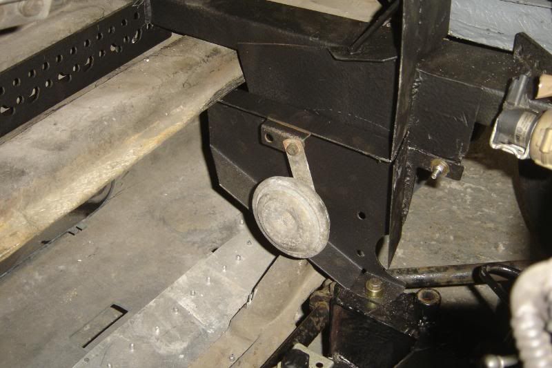
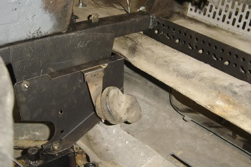
Got the SS M6 bolts and nylocs this morning so I've bee able to put the nose supports in, and horns,
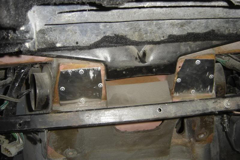
I also got some more hardener in town this morning so was able to use the body filler again. I sealed up in right side blower pipes as there is only one blower now. The drivers side vent will get its air from the left side via the back of the heater box (but not going through it). I clamped it shut in the vice then shoved some filler in it to close the gaps properly.
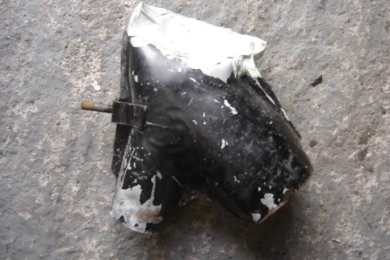
Then put a load inside too, to help it flow a little better (perhaps a little overkill for a vent )
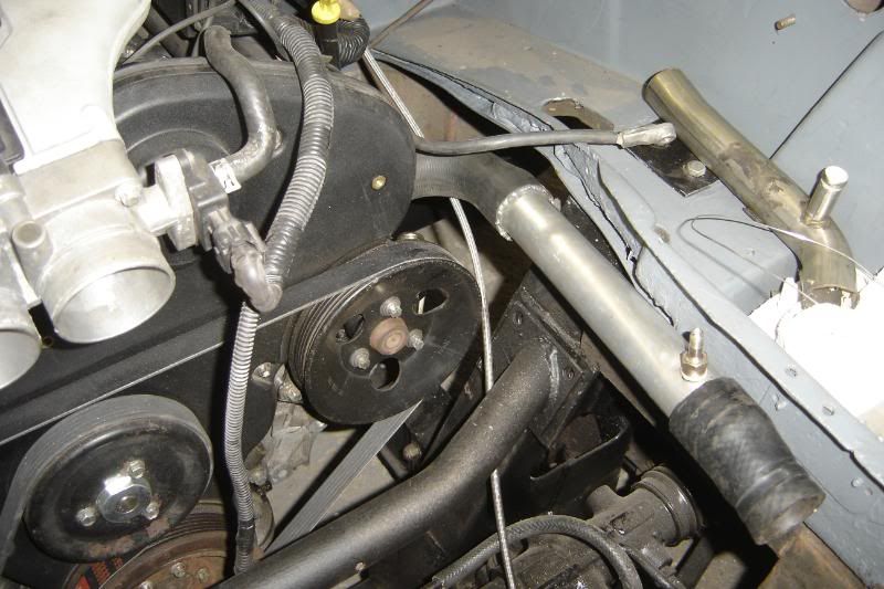
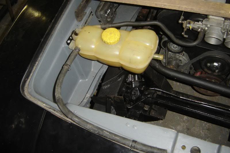
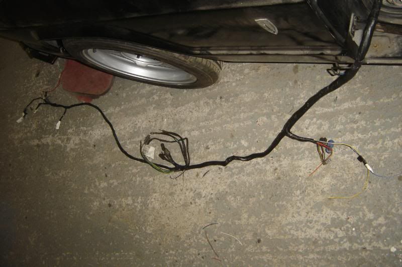
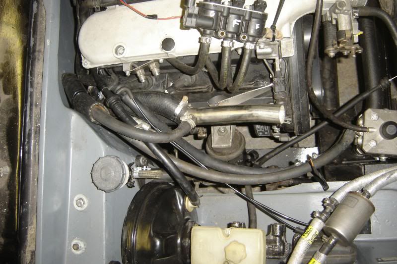
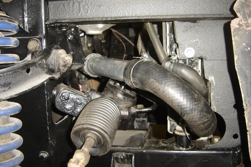
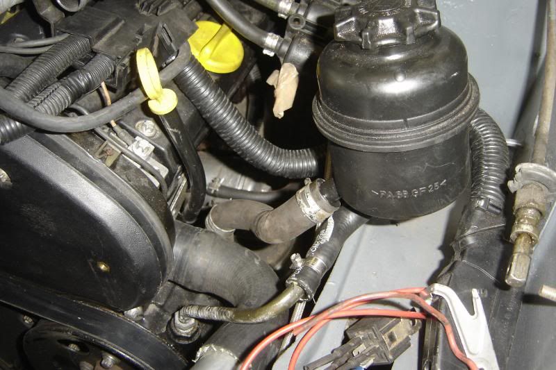
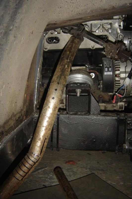
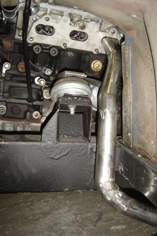
I've rerouted the hoses to be low. So the hot from the engine to the vaporiser, and from there to the matrix both take the low road along the chassis, this photo is a bit of a shocker but you can see the hoses going up to the vaporiser on the right and down to the chassis legs
Leaving just the two hoses up high, the main one from the radiator and the return from the matrix, I can't move the big hose without taking hte engine out and redesigning the outlet (and I can't be arsed with that). So I'll have to bleed this carefully and with a CBS bleed insert, on the plus side the expansion tank can be raised by nearly a foot with all the hoses remaining connected.
The expansion tanks main hose goes down to an inlet on the radiator via a recycled bit of omega SS tube.
The main hose from radiator to engine is now connected up, it goes over the front of the head (lower than the bleed point) and down over the rack then round.
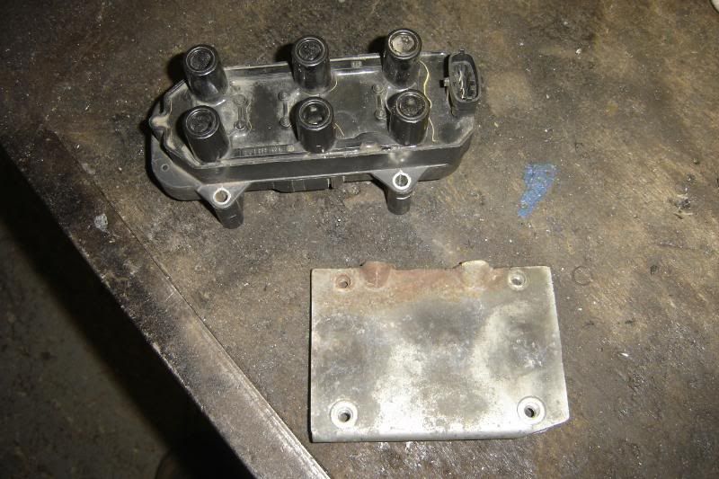
I'd been pondering the Coil pack for a while as it used to be behind the head, in the hardest to reach place on earth. That will now be mounted on the front suspension tower support bar thingy. Recycled the bracket.
Put it on the bar
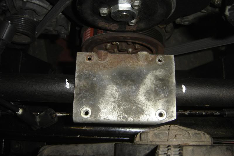
you get teh idea
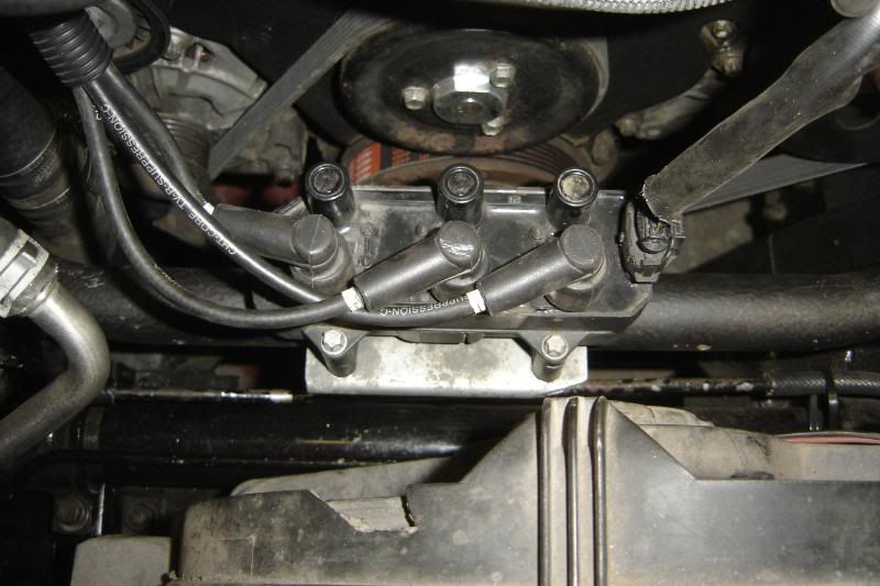
And now its covered in stone chip, drying
More to come
Got the SS M6 bolts and nylocs this morning so I've bee able to put the nose supports in, and horns,
I also got some more hardener in town this morning so was able to use the body filler again. I sealed up in right side blower pipes as there is only one blower now. The drivers side vent will get its air from the left side via the back of the heater box (but not going through it). I clamped it shut in the vice then shoved some filler in it to close the gaps properly.
Then put a load inside too, to help it flow a little better (perhaps a little overkill for a vent
)I've rerouted the hoses to be low. So the hot from the engine to the vaporiser, and from there to the matrix both take the low road along the chassis, this photo is a bit of a shocker but you can see the hoses going up to the vaporiser on the right and down to the chassis legs
Leaving just the two hoses up high, the main one from the radiator and the return from the matrix, I can't move the big hose without taking hte engine out and redesigning the outlet (and I can't be arsed with that). So I'll have to bleed this carefully and with a CBS bleed insert, on the plus side the expansion tank can be raised by nearly a foot with all the hoses remaining connected.
The expansion tanks main hose goes down to an inlet on the radiator via a recycled bit of omega SS tube.
The main hose from radiator to engine is now connected up, it goes over the front of the head (lower than the bleed point) and down over the rack then round.
I'd been pondering the Coil pack for a while as it used to be behind the head, in the hardest to reach place on earth. That will now be mounted on the front suspension tower support bar thingy. Recycled the bracket.
Put it on the bar
you get teh idea
And now its covered in stone chip, drying
More to come
Lots more looking and thinking today, but puhaps a little more productive than usual in terms of knowing where I'm going with the exhaust manifolds now.
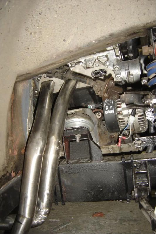
First of all I put the painted suspension tower strut back on and mounted the coil pack to it. The I found a series of hoses that meant I could bodge up the power steering pump until I've decided whether or not I need it (when the car is running) I still need to mount it properly.
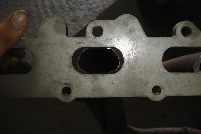
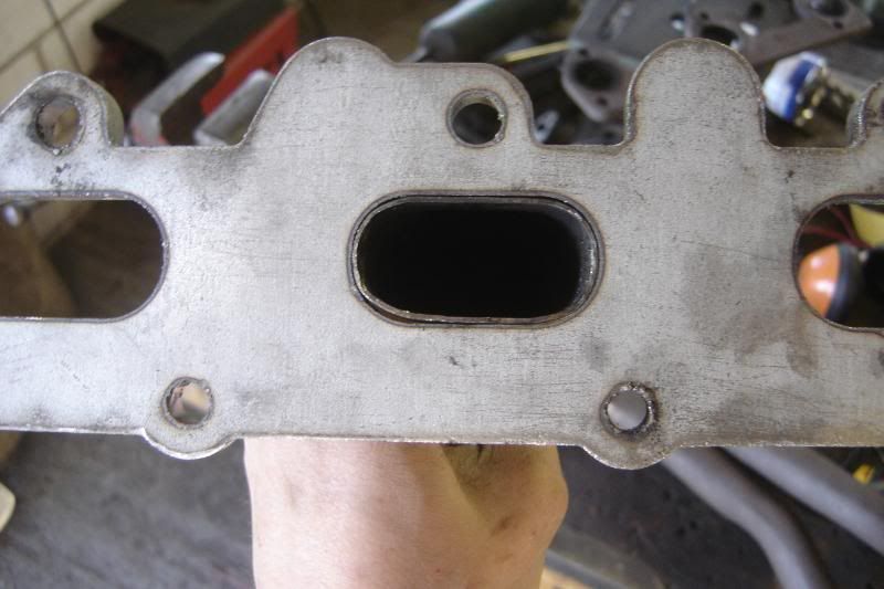
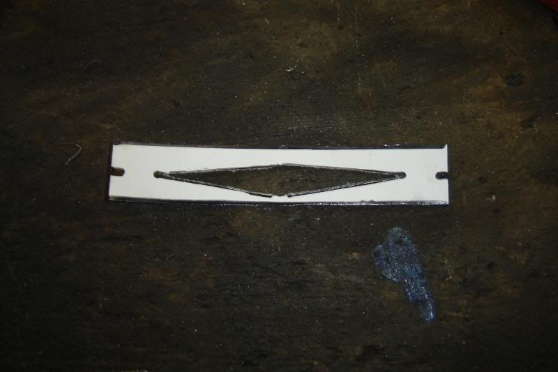
Next was to start tacking the job I've been putting off for a while, making the exhaust manifolds. I cut the flange off one of the existing essex tubular manifolds, and attempted to make the centre pipe the right profile to fit the oval port shape of the header plate, it soon became apparent that this wasn't going to be the right size pipe. As you can see.
I then spent a long long time on the internet trying to the correct diameter and length primaries for this engine. I found a calculator based on A Graham Bells book (I'm lead to believe this is one of the bibles in tuning). http://www.wallaceracing.com/header_length.php
It suggest I need 1.52mm diameter 26.36" length primary pipes. This is frustrating as the original maniold has primaries around that length, but not quite the right diameter especiall aound the bends.
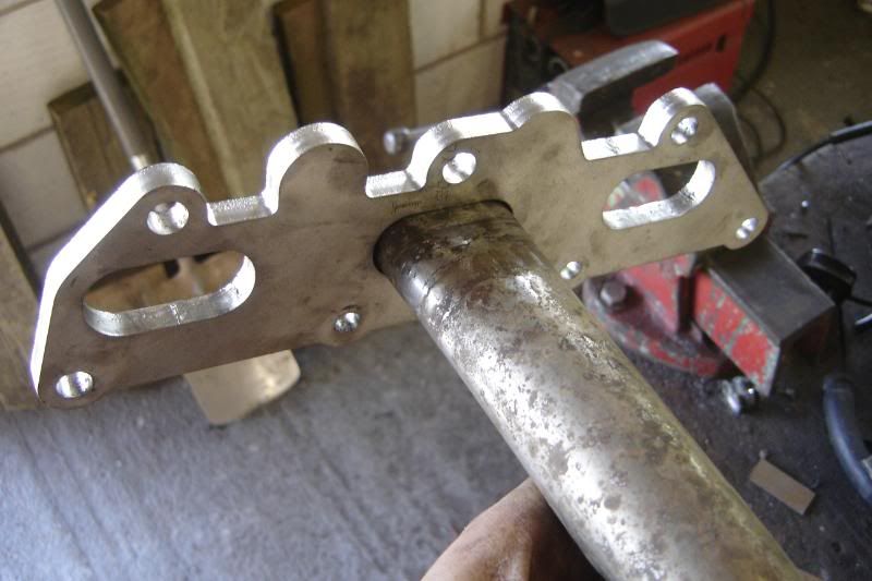
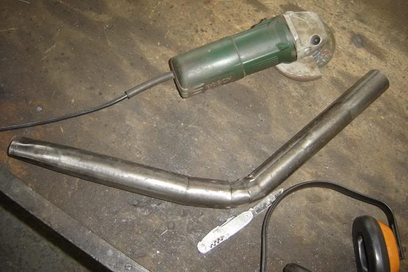
I've got some exhaust pipe up in the rafters of the garage so I measure it up and found it to be the perfect diameters, so the butchery began.
Shaped it a bit
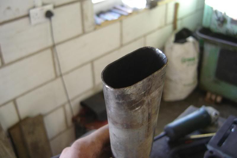
And bingo, a perfect fit.
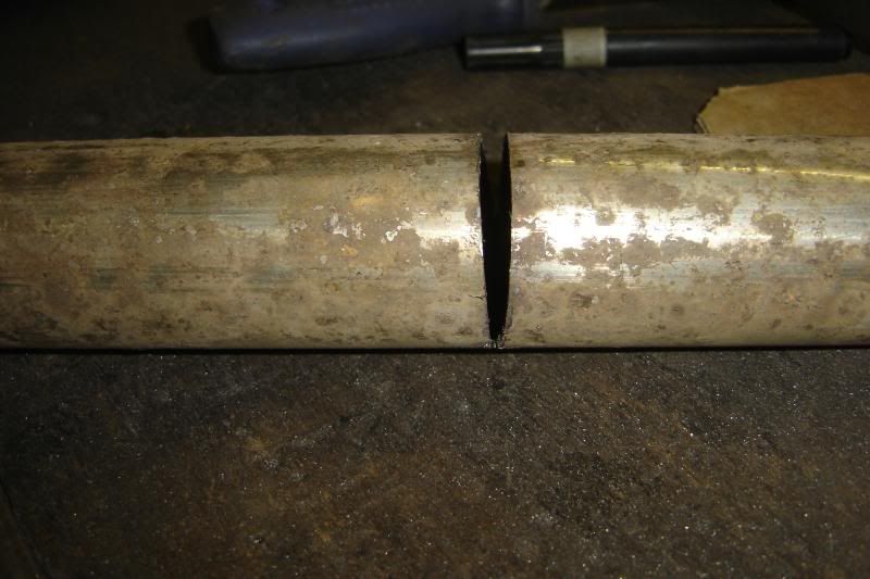
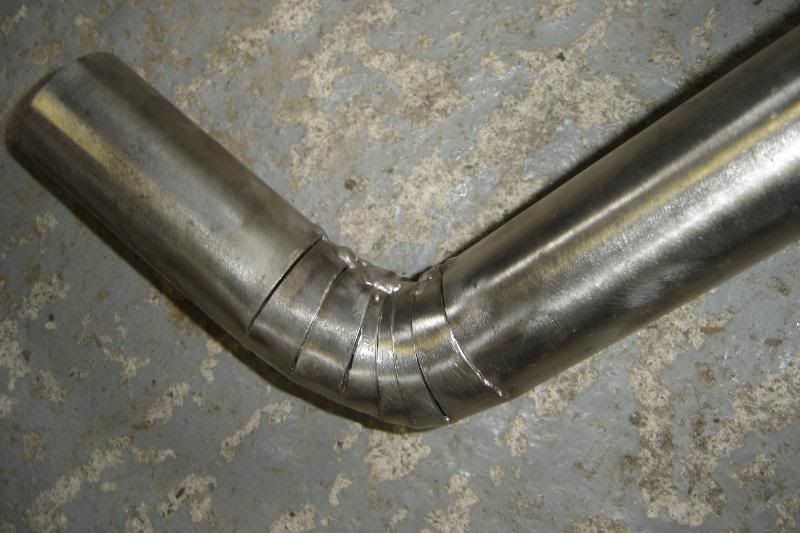
I'm doing the bend by cutting sections out, bending whats left and welding them closed, very time consuming.
But we're getting there slowy
More to come
First of all I put the painted suspension tower strut back on and mounted the coil pack to it. The I found a series of hoses that meant I could bodge up the power steering pump until I've decided whether or not I need it (when the car is running) I still need to mount it properly.
Next was to start tacking the job I've been putting off for a while, making the exhaust manifolds. I cut the flange off one of the existing essex tubular manifolds, and attempted to make the centre pipe the right profile to fit the oval port shape of the header plate, it soon became apparent that this wasn't going to be the right size pipe. As you can see.
I then spent a long long time on the internet trying to the correct diameter and length primaries for this engine. I found a calculator based on A Graham Bells book (I'm lead to believe this is one of the bibles in tuning). http://www.wallaceracing.com/header_length.php
It suggest I need 1.52mm diameter 26.36" length primary pipes. This is frustrating as the original maniold has primaries around that length, but not quite the right diameter especiall aound the bends.
I've got some exhaust pipe up in the rafters of the garage so I measure it up and found it to be the perfect diameters, so the butchery began.
Shaped it a bit
And bingo, a perfect fit.
I'm doing the bend by cutting sections out, bending whats left and welding them closed, very time consuming.
But we're getting there slowy
More to come
I'm getting on fairly well with the bigger tube now, I've made a jig to help cutting the tube.
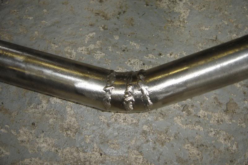
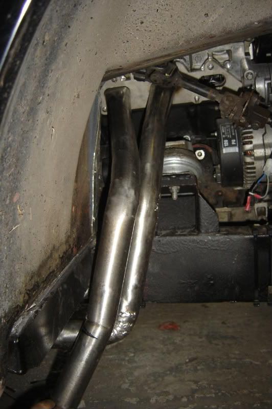
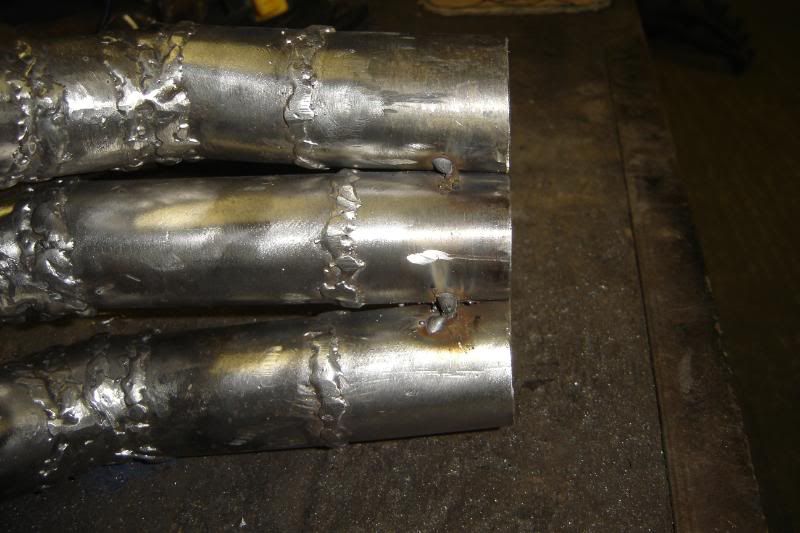
The first tube is all finished and welded up now, before weld
And after welding, not too neat yet but getting used to the SS welding again.
Made some ground on the seond primary pipe now too,
More to come
The first tube is all finished and welded up now, before weld
And after welding, not too neat yet but getting used to the SS welding again.
Made some ground on the seond primary pipe now too,
More to come
Got some more done this afternoon
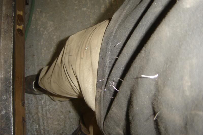
You know when your wire wheel is about to give up when it keeps spitting bits of wire at you
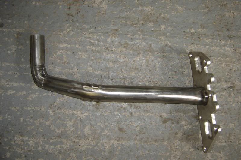
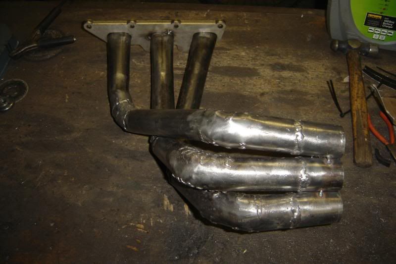
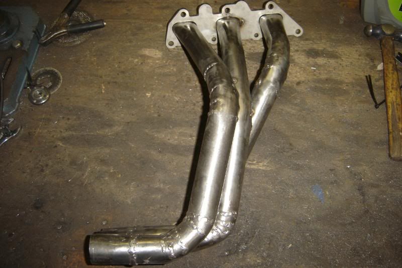
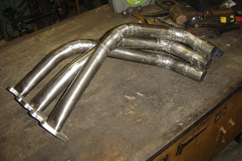
Got the two pipes all welded up after lunch, The second pipe isn't attached to the header plate yet as I have to extend the primaries a bit cos they've lost length in all the bends
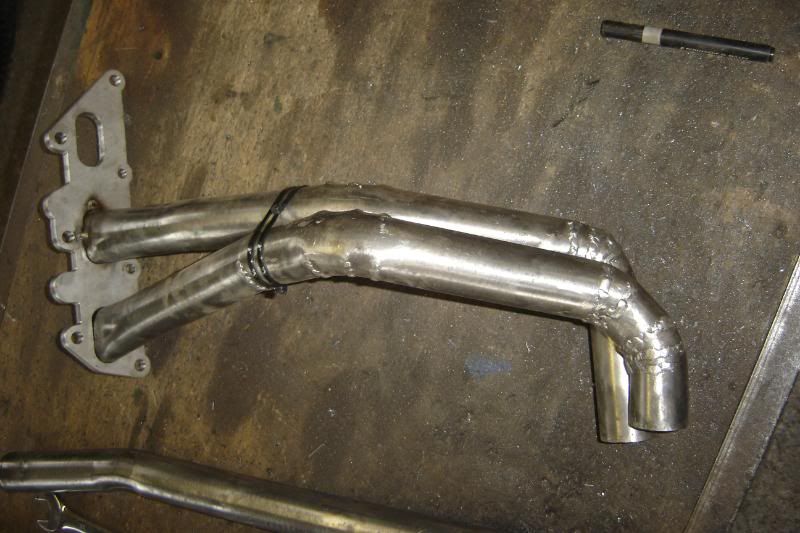
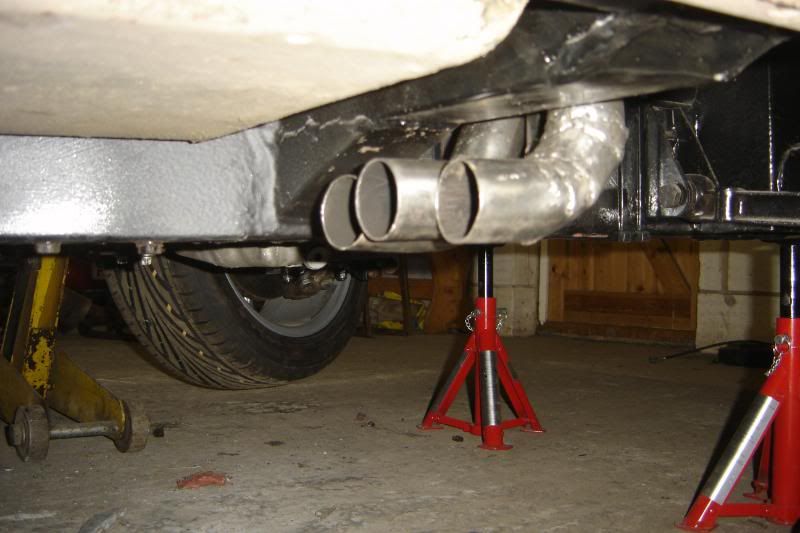
This is where I'm at at the moment. Again the outwe two pipes aren't attached yet but al the bends are now in place and the tubes end in the right place. With the originals bottoming out on the road I was reluctant to make the collector the same design as it leaves at least one pipe a little exposed to damage, especailly as they're bigger diameter, so I'm going to make a flat collector, that goes into a 2.5 inch exhaust. Thats a good increase on the original 2.25 inch. The websire suggests 3 inch but thats so big, its heading for boyracer terratory. And The surpra I had made 200bhp on one 2.5 inch pipe so I can't see it being a big restriction for the v6 (having two pipes an all).
Some photos then.
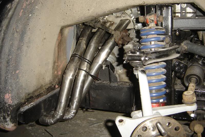
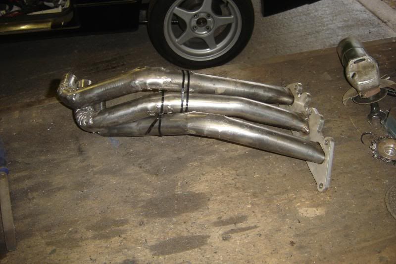
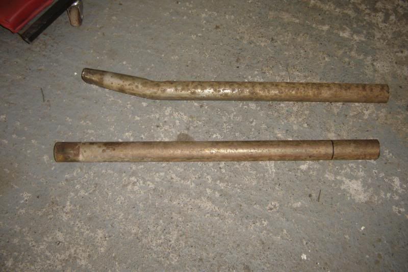
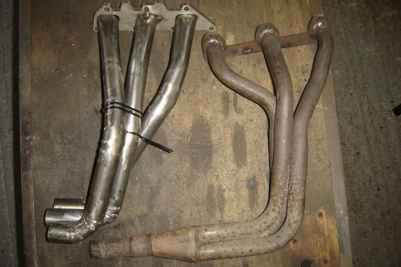
The pipes look way larger than the originals but I think this is partly cos they're closer together, so here's a side by side photo to comparison.
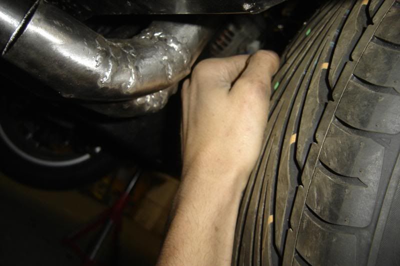
There is still room enough to get a fist between the wheel and the manifold with the suspesion jacked up nearly to where it'll be
More to come
You know when your wire wheel is about to give up when it keeps spitting bits of wire at you
Got the two pipes all welded up after lunch, The second pipe isn't attached to the header plate yet as I have to extend the primaries a bit cos they've lost length in all the bends
This is where I'm at at the moment. Again the outwe two pipes aren't attached yet but al the bends are now in place and the tubes end in the right place. With the originals bottoming out on the road I was reluctant to make the collector the same design as it leaves at least one pipe a little exposed to damage, especailly as they're bigger diameter, so I'm going to make a flat collector, that goes into a 2.5 inch exhaust. Thats a good increase on the original 2.25 inch. The websire suggests 3 inch but thats so big, its heading for boyracer terratory. And The surpra I had made 200bhp on one 2.5 inch pipe so I can't see it being a big restriction for the v6 (having two pipes an all).
Some photos then.
The pipes look way larger than the originals but I think this is partly cos they're closer together, so here's a side by side photo to comparison.
There is still room enough to get a fist between the wheel and the manifold with the suspesion jacked up nearly to where it'll be
More to come
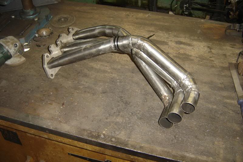
Well, all the primary pipes are fulled welded up, ground back and "wire wheeled". Each pipe has been extended so that they all fall between 26.25 and 27 inches in length, and line up with each other for the collector to be made next. I'm chuffed with how they've come out, the welding might look like bird poo on the outside but I made sure there were no burrs before closing each bend section and they look really smooth inside I might wrap them to hide the welds
They're well tacked in place at the moment so besides the collector its just the pipes to header plate that needs welding up now, I'll do that really slowly I think to keep warping to a minium. Oh and make the other side!
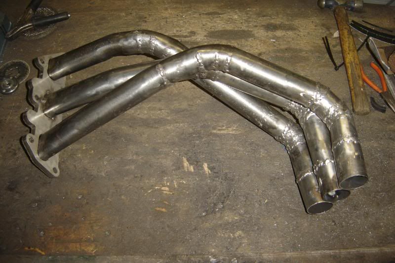
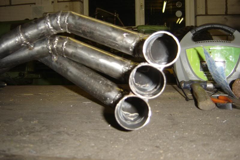
I might have got a little too enthusiastic with the camera
I might wrap them to hide the welds They're well tacked in place at the moment so besides the collector its just the pipes to header plate that needs welding up now, I'll do that really slowly I think to keep warping to a minium. Oh and make the other side!
I might have got a little too enthusiastic with the camera
Had to head for town this morning for some more cutting discs, welding wire and wire wheel. Then I got on with welding up the pipes to the header plate, the right side is all done now, I'll do the collector when I know more about what exhaust system I'm going to fit.
Here's a little piccie so of the limited progress made on the left side.
I got this far and decided to give it a break as my face was beggining to hurt. There are so much dust and fumes from this job, I soon get a headache and can feel the dust in my head its horrible, so I wear this beastly, full face dust mask, its really heavy and the it rubs my face every time I put it on and take it off
That enough of the wining!
So instead I thought I'd have a go on the lathe. I've hatched a little plan to do away with the PAS pump until I know for sure if I need it or not. Its involved changing the pulley but otherwise the pump has remained unharmed, and I've already bought another pulley incase I want the pump after all.
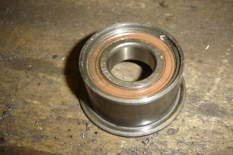
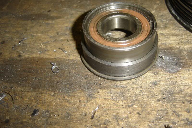
So I took one of the old cam belt idlers, which I'm sure isn't that old at all, the bearing feels really tight.
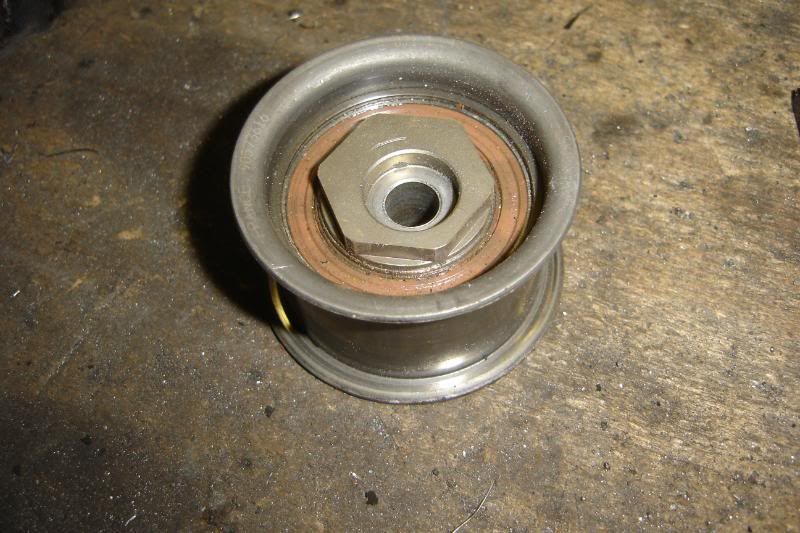
And took the edge off it on the lathe
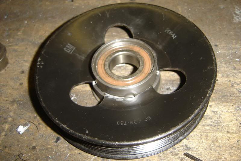
Then took the locating centre of the pulley out a bit, from this
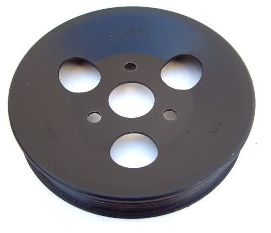
To this
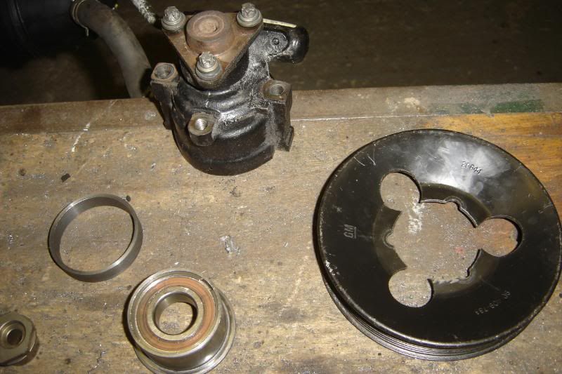
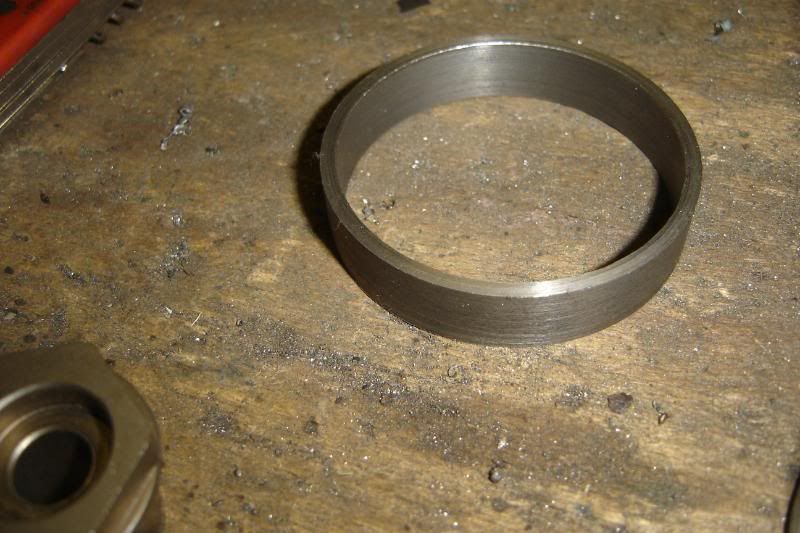
Made a collar from an old smaller pulley I had lying around
The collar holds the pulley in the right place, so its centre is over the centre of the bearing, so there is no nasty loads on the bearing.
And here you have it, ready to be welded on.
The collar is conveniently cast iron so I'll grind some weak points into it and when the welding is done the collar can be broken off and the pulley welded on the back too.
I've yet to make the mount for this but I think it'll end up being better than having a reseroir full of oil perminantly circulating.
Hopefully I'll get more done on the manifold tomorrow.
More to come
Here's a little piccie so of the limited progress made on the left side.
I got this far and decided to give it a break as my face was beggining to hurt. There are so much dust and fumes from this job, I soon get a headache and can feel the dust in my head its horrible, so I wear this beastly, full face dust mask, its really heavy and the it rubs my face every time I put it on and take it off
That enough of the wining!
So instead I thought I'd have a go on the lathe. I've hatched a little plan to do away with the PAS pump until I know for sure if I need it or not. Its involved changing the pulley but otherwise the pump has remained unharmed, and I've already bought another pulley incase I want the pump after all.
So I took one of the old cam belt idlers, which I'm sure isn't that old at all, the bearing feels really tight.
And took the edge off it on the lathe
Then took the locating centre of the pulley out a bit, from this
To this
Made a collar from an old smaller pulley I had lying around
The collar holds the pulley in the right place, so its centre is over the centre of the bearing, so there is no nasty loads on the bearing.
And here you have it, ready to be welded on.
The collar is conveniently cast iron so I'll grind some weak points into it and when the welding is done the collar can be broken off and the pulley welded on the back too.
I've yet to make the mount for this but I think it'll end up being better than having a reseroir full of oil perminantly circulating.
Hopefully I'll get more done on the manifold tomorrow.
More to come
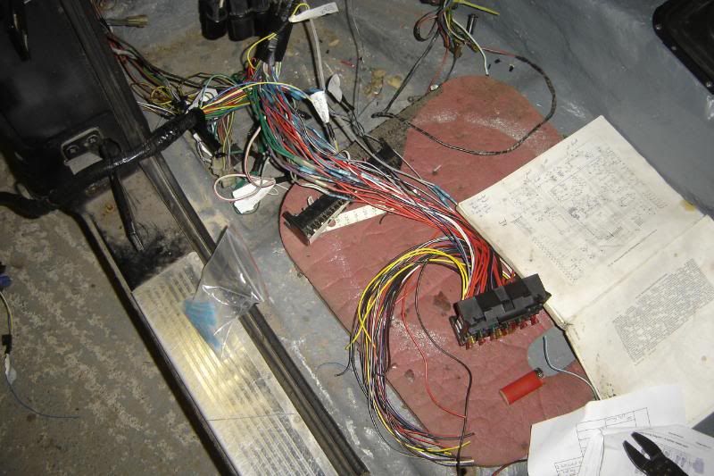
I spent today looking at the wiring and I've nearly completed the wiring from the bulkhead mounted terminal and most of the ECU conectors too. I phoned a friend and aasked a few questions about when he did his loom and he suggested red insulation tape and a sharpy perminant marker, and label everything. So I have been and it seems to work really well.
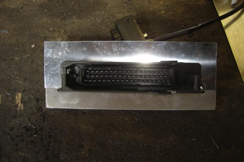
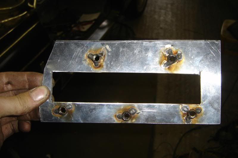
I've started making the mounting face for the terminal.
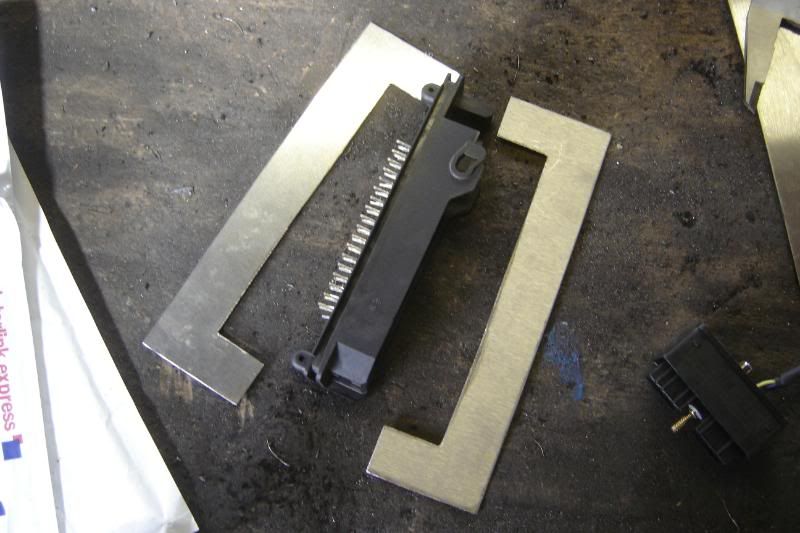
And here's the new bit of loom coming together
I'll get somemore tubes of araldite and flood the area where the connecotrs are soldered on to stop any movement and seal it up (after I've soldered on lots of spare connections just in case).
More to come.
I've started making the mounting face for the terminal.
And here's the new bit of loom coming together
I'll get somemore tubes of araldite and flood the area where the connecotrs are soldered on to stop any movement and seal it up (after I've soldered on lots of spare connections just in case).
More to come.
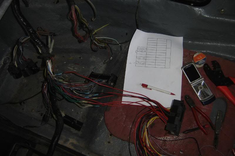
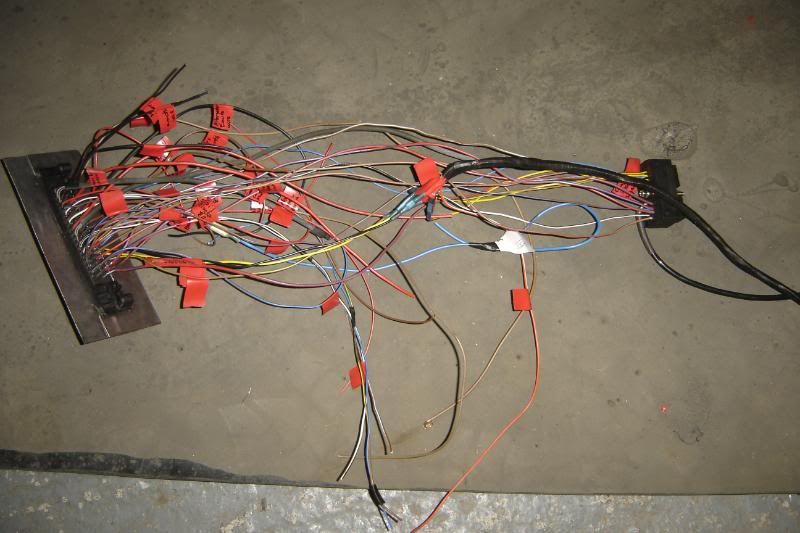
Made great progress with the wiring today, it might not look much but this section of loom has taken two days to make and represents "breaking the back" of the wiring job
I'm well pleased with it, whats left to do is much easier.
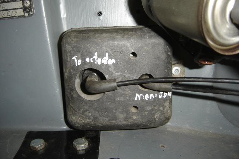
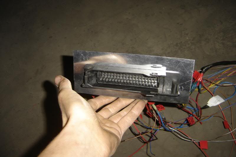
To recap: This is the connector that was the omega ECU, I angle grinded the circuit boards off and used it as an engine connection. So this will mount in the bulkhead and every connection to the engine will go through this terminal.
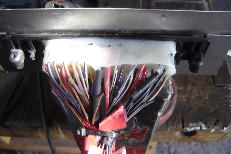
This is the connectors all soldered on (with 7 spare wires). I put some plastic sheet around the connecotrs and flooded it with araldite to seal it up, make sure there can be no shorts and make it more robust. This is the part that will be facing backwards towards the glove box.
I started off doing all the connections between the engine terminal and ECU terminal
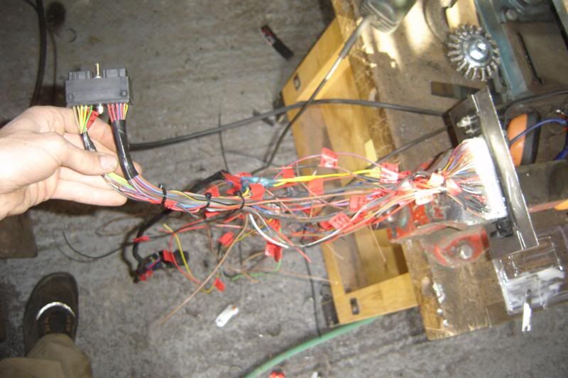
And now its a whole independant section of loom, fully labelled so it can be removed and worked on in future.
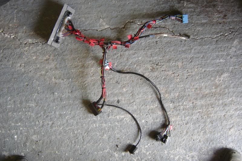
So top left is the engine terminal (bulkhead mounted), bottom left is the ECU terminal and laptop serial connection, next to the serial connection are the LPG injector intercept connections to the LPG ECU, and top right is the connection from all that stuff to the cars loom, through a great little rachet terminal that I harvested from the omega passenger footwell
I've really enjoyed doing the loom I think I'm weird
More to come.
I'm well pleased with it, whats left to do is much easier.
To recap: This is the connector that was the omega ECU, I angle grinded the circuit boards off and used it as an engine connection. So this will mount in the bulkhead and every connection to the engine will go through this terminal.
This is the connectors all soldered on (with 7 spare wires). I put some plastic sheet around the connecotrs and flooded it with araldite to seal it up, make sure there can be no shorts and make it more robust. This is the part that will be facing backwards towards the glove box.
I started off doing all the connections between the engine terminal and ECU terminal
And now its a whole independant section of loom, fully labelled so it can be removed and worked on in future.
So top left is the engine terminal (bulkhead mounted), bottom left is the ECU terminal and laptop serial connection, next to the serial connection are the LPG injector intercept connections to the LPG ECU, and top right is the connection from all that stuff to the cars loom, through a great little rachet terminal that I harvested from the omega passenger footwell
I've really enjoyed doing the loom I think I'm weird
More to come.
I did anther bucket load of wiring today, having the omega as a supply of wires has been awesome. The cars loom is nearly done now, all the new relays are in for the ECU the fuse box finished (I put some extras in today before neatening it up a bit. All thats left in terms of wiring is redo the central consol panal with some extra switches for fuel pumps and connect them all up
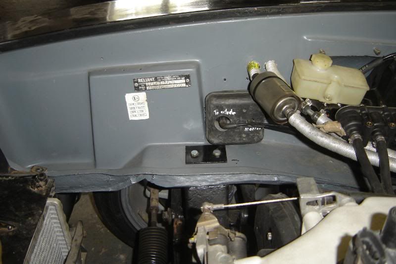
I got the "engine to ecu to car" section of loom in this afternoon
Made a little back plate with welded nuts to hold the terminal in sercurely, and burnt my little finger
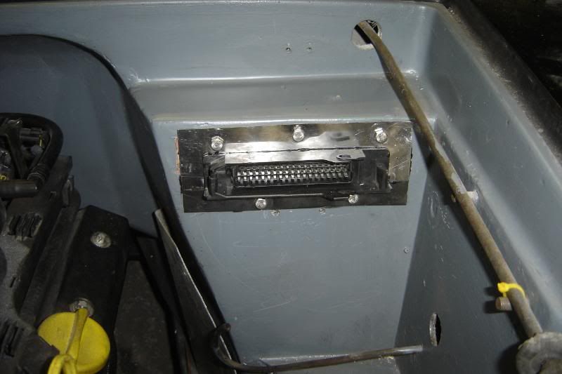
And this is how it looks all finished
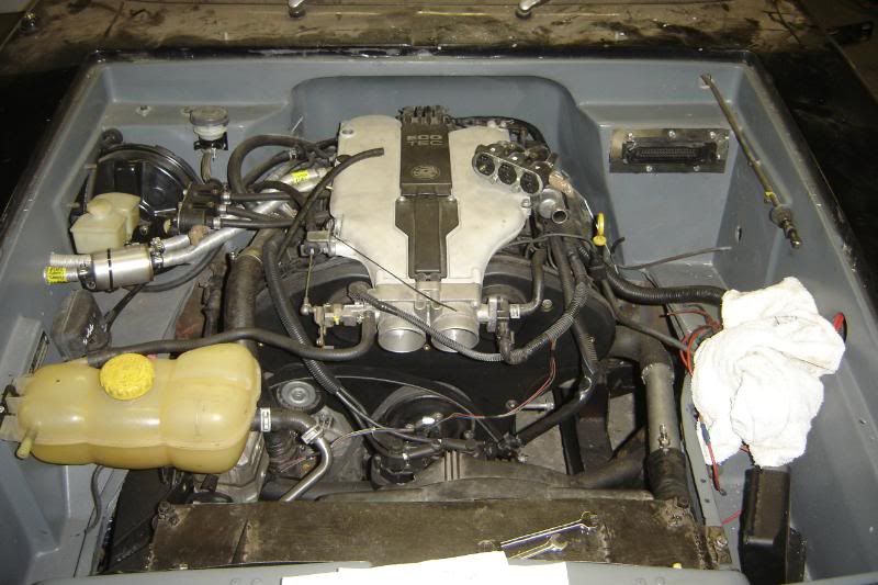
Exciting new, I connected the ECU up and the laptop and it all works its not running or anything but all the sensor inputs come up on the laptop screen. Never have I been so excited to push a pedal and see a bar move on a laptop screen.
More to come
I got the "engine to ecu to car" section of loom in this afternoon
Made a little back plate with welded nuts to hold the terminal in sercurely, and burnt my little finger
And this is how it looks all finished
Exciting new, I connected the ECU up and the laptop and it all works
its not running or anything but all the sensor inputs come up on the laptop screen. Never have I been so excited to push a pedal and see a bar move on a laptop screen. More to come
Edited by lozzzzzz on Friday 2nd September 21:53
The whole thing is sealed and the terminal is sealed to the bulkhead it should be alright.
ITS RUNNING
it took a while to figure out that the crank sensor wire were the wrong way round but as soon as that was sorted, and the ECU gave the green light, I connected the pumps and it lived, I'm over the moon.
Its been such an awesome summer, but hte updates won't be this frequent for a couple of months now
Thanks for all those following.

Gassing Station | Scimitar | Top of Page | What's New | My Stuff