Tamiya 1:72 Mosquito FB Mk.VI
Discussion


sad61t said:
Hi dr_gn,
There's a brief shot of a part built Mosquito at a Canadian museum here:
https://youtu.be/ZE8d3ChFuAM?t=17m10s
At about 17:20 it is shown in what looks like bare wood finish, they are using all the actual materials and an authentic manufacturing process. More info here: http://www.ch2a.ca/#!mosquito/c1tsl
Thanks very much - the second link has some great references.There's a brief shot of a part built Mosquito at a Canadian museum here:
https://youtu.be/ZE8d3ChFuAM?t=17m10s
At about 17:20 it is shown in what looks like bare wood finish, they are using all the actual materials and an authentic manufacturing process. More info here: http://www.ch2a.ca/#!mosquito/c1tsl
I'm making progress - just painting all the bits that aren't wwod finish like wheels, cockpit etc., ready to fir onece the airframe is finished, plus doing the same in parallel with the Spitfire.
Bit of progress:
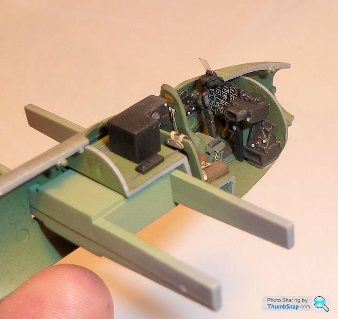
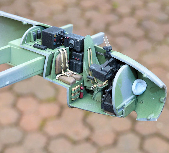
Cockpit partially complete - I added Eduard pre-painted harnesses, since the kit decals look a bit crap:
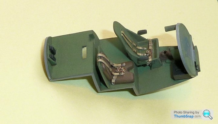
Cockpit sides painted - all the ejector marks will not be seen once complete:
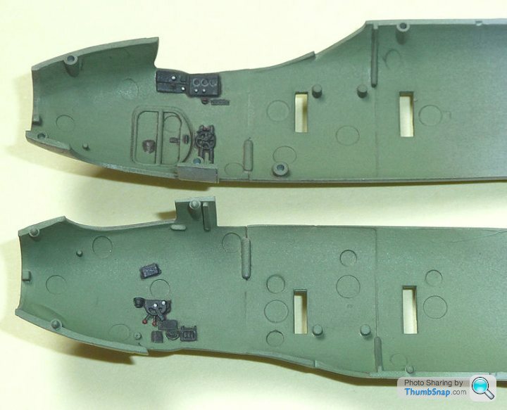
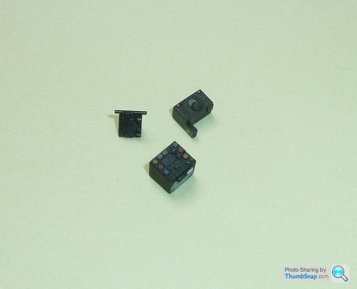
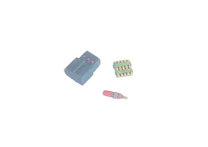
Radio Tx & Rx and electical panels painted:
Just need the instrument panel finishing, and a few wires adding and that will do - it's not a super-detal job.
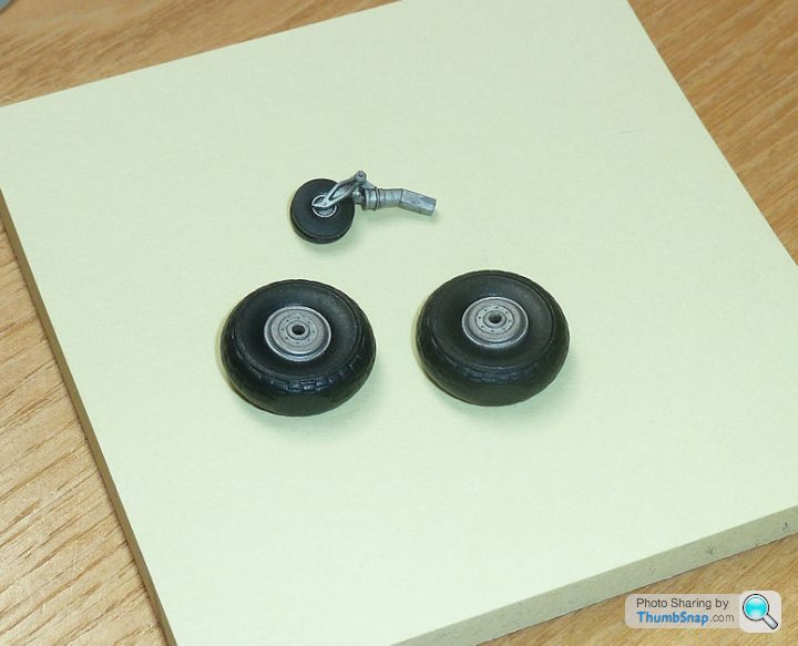
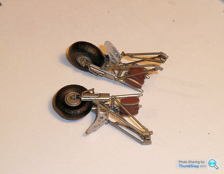
And the wheels (filed some flats on them), which need a coat of matt varnish:
Then get the fuselage assembled...
Cockpit partially complete - I added Eduard pre-painted harnesses, since the kit decals look a bit crap:
Cockpit sides painted - all the ejector marks will not be seen once complete:
Radio Tx & Rx and electical panels painted:
Just need the instrument panel finishing, and a few wires adding and that will do - it's not a super-detal job.
And the wheels (filed some flats on them), which need a coat of matt varnish:
Then get the fuselage assembled...
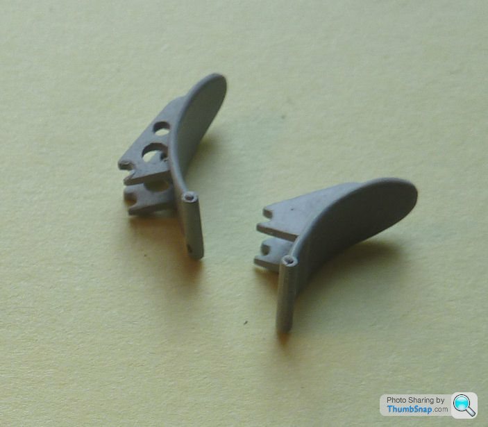
Started to drill out the mudguard brackets in accordance with Eskimo's reference pics:
And made a start on the instruments. Good illustration of why aftermarket parts can increase the complexity and duration of a build by several orders of magnitude - the Eduard blind flying instrumet panel didn't have an apaerture for the gunsight to be fitted, and once identified and modified to the extent needed to fit, it looked terrible:
So I've opted to go for the original decal for the main panel, and the Eduard stuff for the peripheral bits. In fact the decal is probably better in this case, since the low-contrast Eduard acetate instruments would be pretty much invisible under the panel cover.
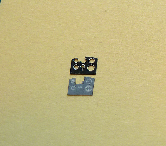
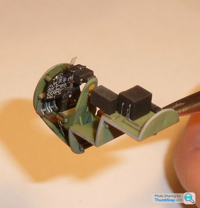
I pressed my home made punch and die set into action again to make some yellow circles for the pilot's seat and bulkhead. There should be one behind the navigator's set too, but it's covered up in this case). I believe the markings are to indicate ferrous or armoured parts within the cockpit, although I think their true function has been lost in the mists of time:
And made a start on the instruments. Good illustration of why aftermarket parts can increase the complexity and duration of a build by several orders of magnitude - the Eduard blind flying instrumet panel didn't have an apaerture for the gunsight to be fitted, and once identified and modified to the extent needed to fit, it looked terrible:
So I've opted to go for the original decal for the main panel, and the Eduard stuff for the peripheral bits. In fact the decal is probably better in this case, since the low-contrast Eduard acetate instruments would be pretty much invisible under the panel cover.
I pressed my home made punch and die set into action again to make some yellow circles for the pilot's seat and bulkhead. There should be one behind the navigator's set too, but it's covered up in this case). I believe the markings are to indicate ferrous or armoured parts within the cockpit, although I think their true function has been lost in the mists of time:

Mk1 through V Spitfires and Hawker Hurricanes had the V6 versions of the Merlin...

As the engines were developed they all ended up with an individual exhaust stack per cylinder. On P39s, the Alison V12 even got an individual stack per exhaust port (24 in total).
Later Mosquitos with the big twin stage supercharged Merlin 60 series engines (given away by longer nacelles and a chin intake below the spinner for the intercooler) had 6 stacks per side unlike the baby Merlins on earlier mark Mossies which had the above configuration.

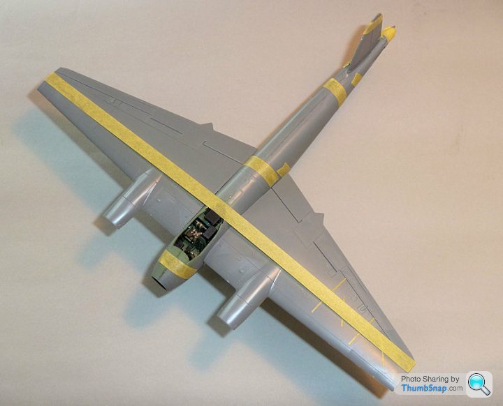
...two coats of sea grey then the fuselage was masked at "83 degrees tangent" and the top surfaces sprayed with 2 coats of ocean-grey and two coats of olive-grey then camouflaged...
These angles were changed at various stages, giving rise to the various heights of demarcations on bombers throughhout the war.
Also read in the same magazine that the wavy upper/lower demarcations seen on many bombers was a result of a misunderstood A/M instruction that the upper and lower camo should have "no definite line of demarcation". What it meant was to have a feathered edge, but was widely interpreted as "shouldn't be a straight edge".
dr_gn said:
I'm intrigued by the angle/masking comment. I wonder if it's something to do with getting the right degree of feathering on the demarcations? Mosquitos do seem to have less well defined edges than Spitfires or Hurricanes of the same era.
Turns out that the angle mentioned defined a line, up from the horizontal, and where this line touched the fuselage (tangentially) was where the demarcation line for the upper/lower camo was.These angles were changed at various stages, giving rise to the various heights of demarcations on bombers throughhout the war.
Also read in the same magazine that the wavy upper/lower demarcations seen on many bombers was a result of a misunderstood A/M instruction that the upper and lower camo should have "no definite line of demarcation". What it meant was to have a feathered edge, but was widely interpreted as "shouldn't be a straight edge".
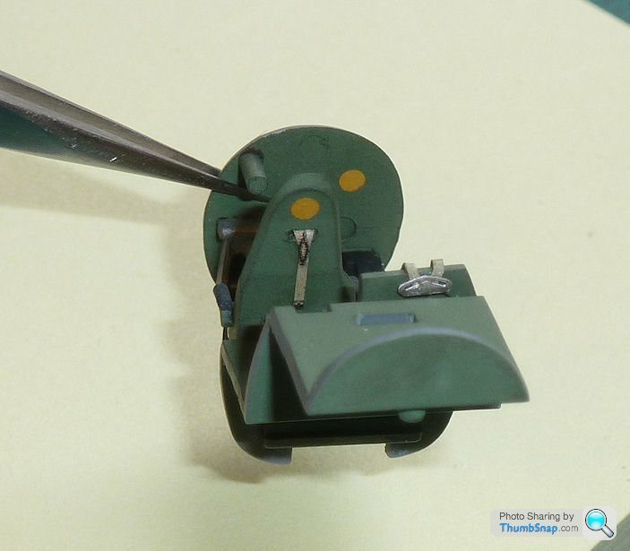
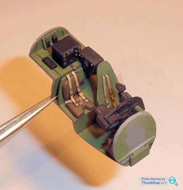
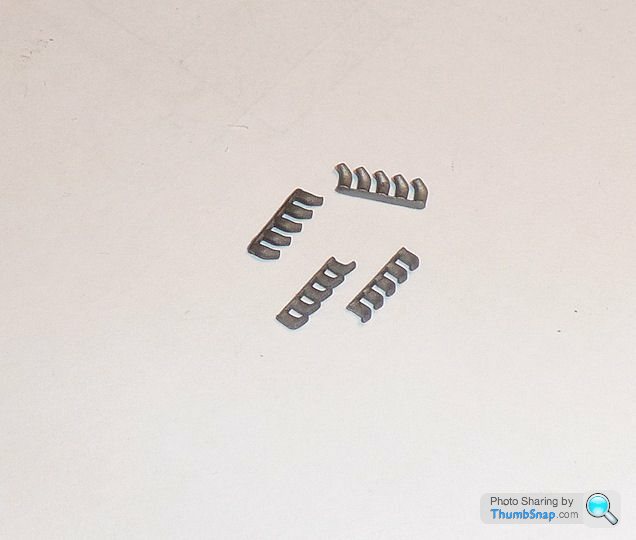
The cockpit still looked a bit sparse, and looking at some reference photos, I thought I'd scratchbuild an additional radio for behind the pilot's seat, a fire extinguisher and what looks like a row of cartridges or flares in front of the navigator's seat:
Looks better now when viewed through the canopy.
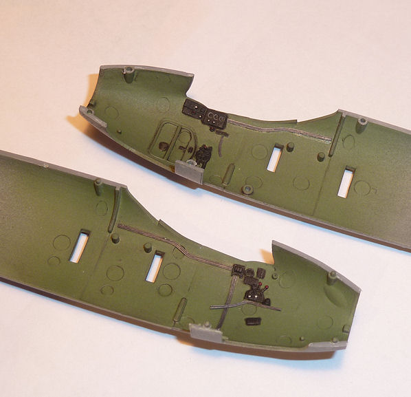
Then assembled the fuselage halves. I temporarily fitted the wings to make sure the spars were aligned while the Araldite set:
Looks better now when viewed through the canopy.
Then assembled the fuselage halves. I temporarily fitted the wings to make sure the spars were aligned while the Araldite set:

The Mosquito has some distinctive framing visible inside the canopy, which is difficult to replicate at small scale. The kit has decals, which are OK, apart from being a strange pea green colour. I had some clear decal film, so I sprayed it interior green:
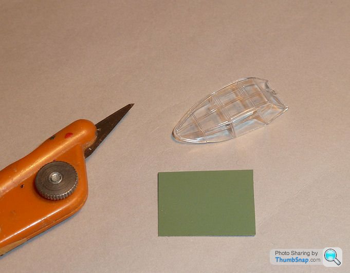
...and cut it into strips which were applied to teh inside surface of the canopy, then the whole thing was dipped in Klear to seal them in:
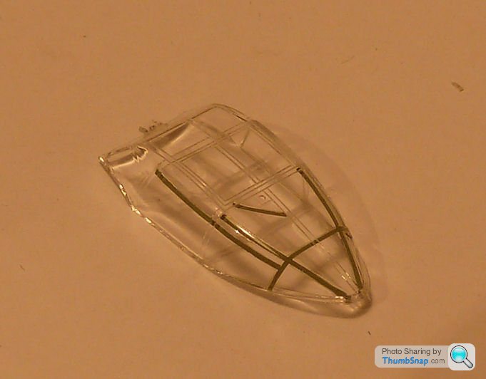
So now its a perfect match for the cockpit, and will hopefully look OK when the outer framing is masked and painted aluminium.
...and cut it into strips which were applied to teh inside surface of the canopy, then the whole thing was dipped in Klear to seal them in:
So now its a perfect match for the cockpit, and will hopefully look OK when the outer framing is masked and painted aluminium.

johnS2000 said:
Having been looking for a punch and die set , might I ask how you made one?
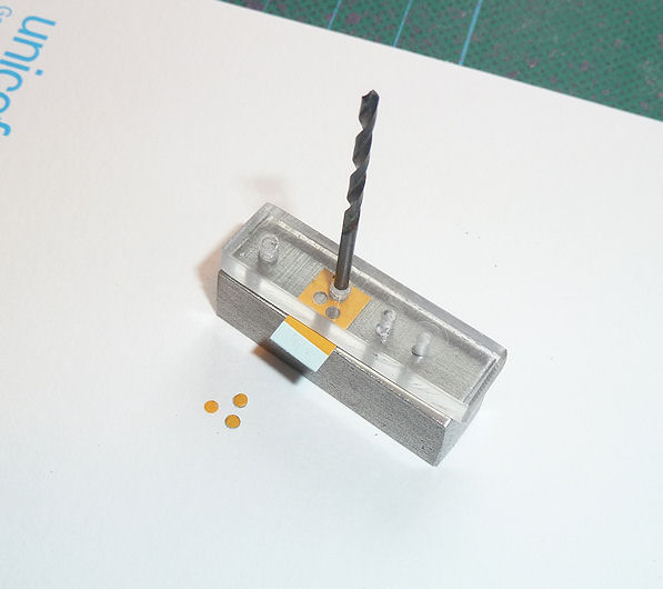
I only just noticed the question about the punch and die:Firstly, it's by no means perfect; I made it for creating a specific sized hole in decal paper for my recent Tornado build.
The principle is that you need to put whatever material you want to punch under a pure shear load, i.e. you need the punch to be a very good fit into the hole, and both punch and hole need to be concentric. Basically I found a piece of steel, and clamped a piece of perspex to it, then drilled through both in four places. This obviously formed four holes through both materials. The two outer holes are then used to align the perspex and steel by means of two twist drills stuck through them. You then put whatever material you want to punch under the perspex, press it down against the steel and using the same drill you used for making the holes, but with the end ground flat, locate it into the perspex and smack it with a hammer. You should end up with neatly punched discs and corresponding holes. I've got a tray full of old drills, and just selected appropriate sizes for the various functions.
I'll get around to making a proper set soon. TBH I've no idea why these sets are so expensive. Same with photo-etch bending tools, I milled mine from scrap aluminium on the manual lathe, with a few bits added from B&Q, and it's been fine. Total cost was, IIRC, considerably less than £5:


Gassing Station | Scale Models | Top of Page | What's New | My Stuff