Ultima Fuel Delivery System Flaw?
Discussion


Storer said:
Steve_D said:
Storer said:
....I like Jonny's idea of wrapping the filter with gold film and any other items may be a good idea. I might look at wrapping the swirl pot.
Paul
Wrapped my swirl pot the other week whilst populating the bulkhead.Paul
Steve
Paul
Steve
Max_Torque said:
What you really need is exhaust header "chimneys" These stainless or pressed alluminium tubes run upwards from the exhaust manifolds, and duct hot air straight out the top of the clip. There were extremely effective at reducing engine bay upheat at low vehicle speeds on the Vanquish S i help develop:

note 4 square chimneys, that mate up to matching grills in the bonnet. Exhaust manifolds are encased, with holes on the underside, so cool air is sucked up and into the system, and ejected at the top, without heating the engine bay nearly so much ;-)
Max, have you got any pics of the headers with their heat shields on? note 4 square chimneys, that mate up to matching grills in the bonnet. Exhaust manifolds are encased, with holes on the underside, so cool air is sucked up and into the system, and ejected at the top, without heating the engine bay nearly so much ;-)
Edited by Max_Torque on Wednesday 25th June 13:29
I do, but they aren't "mine" to publish unfortunately ;-(
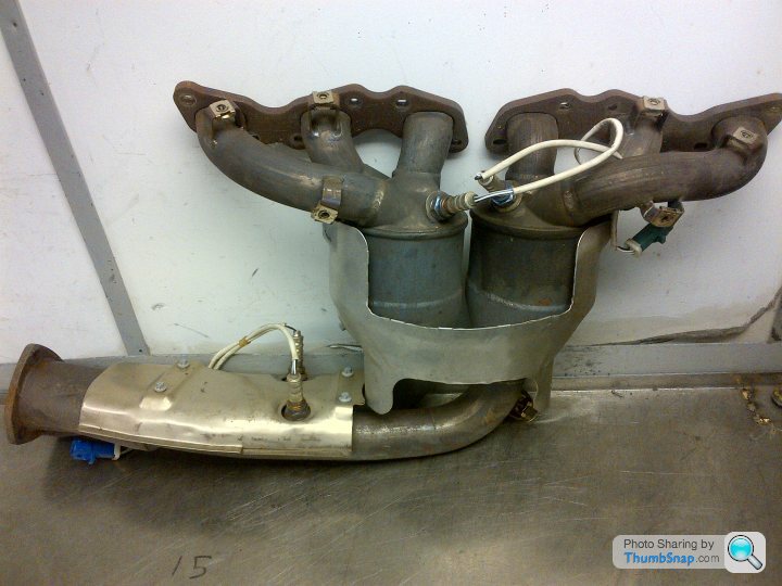
Effectively, the tubular exhaust manifolds (and twin starter cats in this case) are completely enclosed in the normal OEM heat shielding (pressed twin skin aluminium with internal airgap), but that shielding has a square exit on the top side that the chimneys push down into, and vents on the under side to allow cool engine bay air to be pulled in.
Here's a manifold with most of the shielding removed, but it shows the general idea:
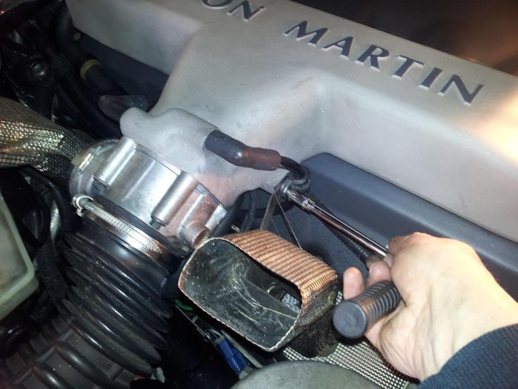
and here's where the chimneys attach:
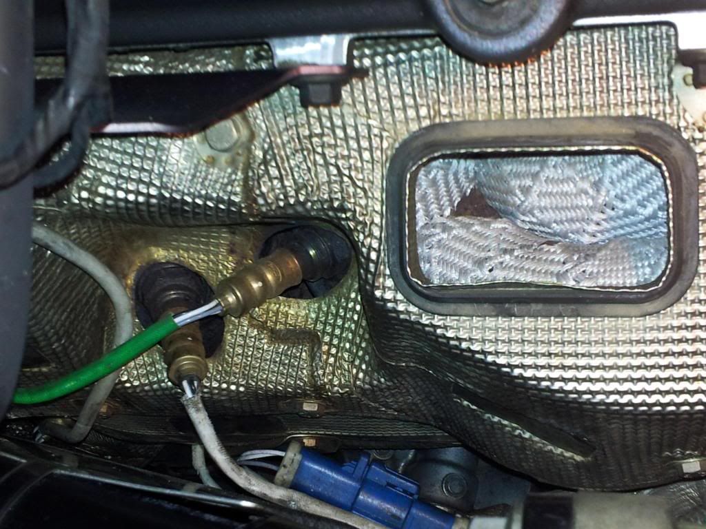
both chimneys shown here:
Effectively, the tubular exhaust manifolds (and twin starter cats in this case) are completely enclosed in the normal OEM heat shielding (pressed twin skin aluminium with internal airgap), but that shielding has a square exit on the top side that the chimneys push down into, and vents on the under side to allow cool engine bay air to be pulled in.
Here's a manifold with most of the shielding removed, but it shows the general idea:
and here's where the chimneys attach:
both chimneys shown here:
Edited by anonymous-user on Thursday 26th June 11:42
chuntington101 said:
Max, thanks for posting. Are the headers also wrapped in a thermal wrap?
Do you need the heat shield to be close to the manifold or could there be some space? Just thinking it would be hard to shape the heat shielding bout could see a general shape with ducts to the top of the clam.
The headers are wrapped also in this case, but this is more to assist catalyst light off. The "external" shielding needs to be a good fit, so the "hot" air doesn't leak out, but it can be some way off the headers themselves. It really just acts as a radiation barrier and to keep the convecting hot air out of the rest of the engine bay.Do you need the heat shield to be close to the manifold or could there be some space? Just thinking it would be hard to shape the heat shielding bout could see a general shape with ducts to the top of the clam.

Max_Torque said:
The headers are wrapped also in this case, but this is more to assist catalyst light off. The "external" shielding needs to be a good fit, so the "hot" air doesn't leak out, but it can be some way off the headers themselves. It really just acts as a radiation barrier and to keep the convecting hot air out of the rest of the engine bay.
How effective is the Zircotec type ceramic coatings?I think it is very effective but I can also see the benefit of the Aston's chimneys. The added problem with the Ultima is that the entire exhaust system is under the clip and it all gets rather warm.
Paul
If you fitted a large enough fan above the engine it could "suck" the car down onto the road for increased grip.........
Paul
If you fitted a large enough fan above the engine it could "suck" the car down onto the road for increased grip.........
For those building or modifying their fuel system I have been sent this which may be obvious to some but useful to others. (Thanks for the link Mark)
Proper Pump Mounting
Jesse Powell: If you talk to most hot rodders, they’ll probably tell you that big external pumps can’t be driven on the street for extended periods of time without vaporlocking because they run too hot. Here’s what’s actually going on. When you buy an Aeromotive pump like an A1000, you get a very detailed set of instructions. They state that the pump must be mounted below the tank or equal to the lowest level of the tank. They also state that the tank must be sumped, and to run an AN-10 feed line from the tank to the pump. If using a pre-pump filter, it is recommended that you use nothing smaller than 100-micron stainless steel. The reason for this is because fuel is no different than any other liquid. Think about your radiator and cooling system. It is under pressure because that pressure raises the boiling point of the coolant. The opposite is true if you put a liquid in a negative pressure environment or a vacuum. The boiling point is actually lowered. A fuel pump obviously pushes fuel to the engine at a desired pressure, but it also sucks fuel to itself. This suction creates a negative pressure environment of vacuum. So, when you use a pickup tube instead of a sump, the pump is no longer gravity fed. The area from the pickup tube to the inlet of a pump is in a vacuum and therefore it’s a place where the fuel can boil quickly. In most fuel system in most cars, fuel is cycled through the system. It goes from the tank to the engine and then is returned. With a pump like an A1000, the entire content of the tank is cycled every four to five minutes. Each time it cycles, the fuel picks up heat from the engine bay, the exhaust and the pavement getting hotter and hotter. Eventually the temperature of the fuel reaches a critical point in which it will actually boil in the pickup tube because of the negative pressure and artificially lowered boiling point. What then starts to happen is that the pump begins to cavitate because it is pulling the fuel to a vapor instead of pulling a liquid. The pump relies on the liquid fuel to keep it cool and lubricated. Eventually the pump or engine will quit because it cannot get fuel. If run dry long enough like this, the pump will vaporlock.
Avoiding these issues is very simple. If you are going to use an external fuel pump, make sure you follow the manufacturer’s recommendations carefully. In our case, it starts at the tank. You need to gravity feed your pump. A properly designed sump creates a new low point in the tank, ensuring fuel remains in that sump at all times, even until the last bit of the tank is emptied. Then, mount your fuel pump lower than the tank or level with that sump. That will keep the pump gravity fed or keep positive pressure on the pump inlet. Once again, remember that positive pressure raises the boiling point, so this set up will be much more forgiving. Also, make sure you use the right line size and a proper filter.
Paul
Storer said:
Posted a good read on the danger of low pressure or vacuum at the high pressure pump inlet
This is why I have been saying for some time now that using the low pressure pumps to pressurise the swirl pot is IMHO the best way to prevent/reduce vapour lock and cavitation at the high pressure pump.Steve
Paul,
Great write up and explanation of how fuel reacts to pressure. When designing my system I read very thoroughly over all the components instructions and Paul is 100% correct. I have both of my pumps mounted slightly below the lowest fitting on the tanks near the center of the bulkhead RH side allowing for a natural gravity feed system to the LP pump. This is the only location that is the lowest point and as far away from the headers as possible. It is best as Paul said to feed the swirl pot via the LP pump and use the HP to circulate the fuel to the rails first then reg last. My return to the tanks via a T with 1.5mm orifices allows for the fuel to evenly trickle back to the top of the tanks and ensures a constant pressure in the swirl pot. Again I reused all the supplied factory pumps, reg, filters. Simply got rid of the antiquated pollak valve, bought a fist full of fittings and some new hose. I have run almost 500 miles on mine now since the conversion with out a hitch even in 90 degree weather in stop and go traffic for over an hour. I like the idea of adding chimneys to the headers however with the rear canopy being GRP I am not sure how a concentrated source of heat would react with it. Dan's yellow GTR rear canopy already changes to a darker yellow when the engine is hot and the entire bulkhead and canopy are heat shielded.
Great write up and explanation of how fuel reacts to pressure. When designing my system I read very thoroughly over all the components instructions and Paul is 100% correct. I have both of my pumps mounted slightly below the lowest fitting on the tanks near the center of the bulkhead RH side allowing for a natural gravity feed system to the LP pump. This is the only location that is the lowest point and as far away from the headers as possible. It is best as Paul said to feed the swirl pot via the LP pump and use the HP to circulate the fuel to the rails first then reg last. My return to the tanks via a T with 1.5mm orifices allows for the fuel to evenly trickle back to the top of the tanks and ensures a constant pressure in the swirl pot. Again I reused all the supplied factory pumps, reg, filters. Simply got rid of the antiquated pollak valve, bought a fist full of fittings and some new hose. I have run almost 500 miles on mine now since the conversion with out a hitch even in 90 degree weather in stop and go traffic for over an hour. I like the idea of adding chimneys to the headers however with the rear canopy being GRP I am not sure how a concentrated source of heat would react with it. Dan's yellow GTR rear canopy already changes to a darker yellow when the engine is hot and the entire bulkhead and canopy are heat shielded.
Gassing Station | Ultima | Top of Page | What's New | My Stuff