Ultima Fuel Delivery System Flaw?
Discussion


deadscoob said:
They're too small, certainly on new tanks. I had those, kept clogging up so binned them and stuck a larger filter on with dry break couplings so the tanks don't need draining if you need to clean them.
a couple of questions.How quickly did they clog?
obviously normal grit and smaller will make it's way through a dry break and in to a filter, but will that tin foil stuff that the tanks are filled with go through a dry break?
Is it me or do some on here like to make things as complicated as possible?
My fuel system works with no issues other than the fact you have to fill both tanks and top the first one when you have filled the second (a bit of theatre for those watching).
If you link the tanks with a large pipe there will be the possibility of surge. Two small pipes still supply enough fuel to keep the tanks even. I can testify to this after running out on the A1 last year. A submersible pump helps to avoid picking up tank debris too.
I like things simple, like me!
Paul
barriejames said:
I do not know enough to stray and form something bespoke
Why not get the help of a willing individual "in the know", you will inevitably find yourself in the same position of many people that have followed the factory route and found themselves having to re-engineer the system.You have a "golden window" to modify your tanks with a large balance pipe during the build.
At least get rid of the Pollack valve, this seems to be the protagonist in a quite a few fuel system hiccups.
Max_Torque said:
If you wanted to run with two "separate" but effectively linked tanks, the best method would be to use two pick up pumps, one in each tank, link the tanks at the top with a big pipe (at least 1" with separate "de-air" pipe to filler neck to allow rapid filling) and link the bottom of the tanks with a small pipe (say 2mm dia to allow long term "leveling" of the contents). Return the swirl pot excess to each tank, using a common run that Tees off to each tank (this will require some careful routing to ensure even flow, but that can be negated to a large degree by using a small restrictor orrifice in each line (ie, to ensure that the static pressure in each line is massively bigger than the pressure drop due to geometry and routing etc) Those small restrictors will also help to pressurise your swirl pot to help your main pressure pump!
Barrie, this is what I have converted to, though I now run two Bosch 044 pressure pumps in place of one (I may be shooting for 900ishBHP in the future).I have had zero problems since bar a failed Aeromotive A1000 high pressure pump.
Justaredbadge said:
a couple of questions.
How quickly did they clog?
obviously normal grit and smaller will make it's way through a dry break and in to a filter, but will that tin foil stuff that the tanks are filled with go through a dry break?
The tanks when new have quite a lot of swarf in and the factory admit the filters will most likely need a clean once or twice - the problem with those little filters is the surface area is so small they get clogged much quicker, so I definitely wouldn't recommend them based on my experience.How quickly did they clog?
obviously normal grit and smaller will make it's way through a dry break and in to a filter, but will that tin foil stuff that the tanks are filled with go through a dry break?
My setup is super simple too, similar to Paul's but without the intank pump. Once I made the changes I mentioned it has been faultless, no issues on warm track days, stuck in traffic or anything else other owners may mention.
The dry break couplings are on the filter so it's a simple unclick, clean and click back in. Cleaning the filter can be done in 5 mins.
deadscoob said:
The tanks when new have quite a lot of swarf in and the factory admit the filters will most likely need a clean once or twice - the problem with those little filters is the surface area is so small they get clogged much quicker, so I definitely wouldn't recommend them based on my experience.
My setup is super simple too, similar to Paul's but without the intank pump. Once I made the changes I mentioned it has been faultless, no issues on warm track days, stuck in traffic or anything else other owners may mention.
The dry break couplings are on the filter so it's a simple unclick, clean and click back in. Cleaning the filter can be done in 5 mins.
Thanks for the info.My setup is super simple too, similar to Paul's but without the intank pump. Once I made the changes I mentioned it has been faultless, no issues on warm track days, stuck in traffic or anything else other owners may mention.
The dry break couplings are on the filter so it's a simple unclick, clean and click back in. Cleaning the filter can be done in 5 mins.
I think the system needs filters in it immediately after the tank otherwise the valve block and the low pressure pump are at risk of debris.
luckily I'm at the perfect point in the build to add these in.

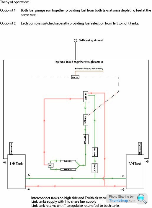
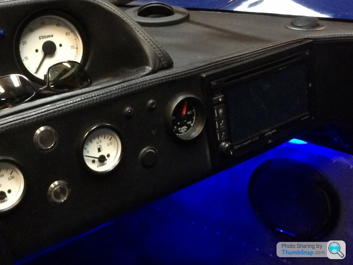
Ok so I have spent the entire weekend replacing the factory fuel system with an all new updated linked tank system. I followed Spatz direction on his system for his updated LS7 engine and basically recreated it. I however ran into an issue, as my tanks are all -6 fittings the return fuel will not equalize fast enough and will fill the return tank to the top of the filler neck before it creates enough pressure to force the fuel to the opposite tank. Version 3 per PDF below. The system otherwise functions fine. I am now thinking the only way to do this with all -6 fittings is to link both supply and return lines with a T to allow the tanks to equalize themselves. Any thoughts on version 4? Trying to keep this system as simple as possible. I did add an Autometer in dash fuel pressure gauge and it read a steady 60 psi at idle and increased slightly with vacuum under power. I highly recommend everyone to add a fuel pressure gauge in the cockpit to allow monitoring of fuel pressure as well as fuel filter condition. The sensor replaced the gauge on the reg and was easily retrofit. After the system is 100% I plan on removing it to document all hose lengths and fittings as well as create a prats list with pix for anyone else looking to do the same. I will also be heat wrapping all fuel lines before they are re installed for the final time. 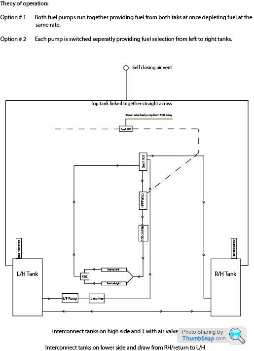

Ultima factory said:
The problems mentioned on this forum and emails to the factory from customers are all mainly related to custom fuel systems that the Ultima Factory have not supplied.
The factory has spent a large amount of time designing, testing and proving the fuel system that they supply for the Ultima and this system has proved to work perfectly on hundreds of Ultima cars, many cars having now covered over 25,000 miles in a variety of worldwide climates. Our fuel system is also supplied with full technical drawings and installation information.
Any reported issues relating to the Ultima supplied fuel system are all fixable with no redesign required, be it simply a case of requiring the cleaning out of a fuel filter for example or adding a fuel filter due to a suspected larger than normal quantity of tank wadding unusually finding its way out of the fuel tank in the case of this thread. For track use we also recommend the fitting of our Ultima fuel surge tank kit in addition to our normal Ultima fuel system.
Note the system that FC previously had fitted to his Ultima was not an Ultima Factory system.
Regards to all,
A valid point, though the system previous to the above was factory and eventually lead to the removal of the Pollack valve for similar reasons to the O.P. and the addition of a high pressure pump system for fuel injection that wasn't a factory option at the time. The factory has spent a large amount of time designing, testing and proving the fuel system that they supply for the Ultima and this system has proved to work perfectly on hundreds of Ultima cars, many cars having now covered over 25,000 miles in a variety of worldwide climates. Our fuel system is also supplied with full technical drawings and installation information.
Any reported issues relating to the Ultima supplied fuel system are all fixable with no redesign required, be it simply a case of requiring the cleaning out of a fuel filter for example or adding a fuel filter due to a suspected larger than normal quantity of tank wadding unusually finding its way out of the fuel tank in the case of this thread. For track use we also recommend the fitting of our Ultima fuel surge tank kit in addition to our normal Ultima fuel system.
Note the system that FC previously had fitted to his Ultima was not an Ultima Factory system.
Regards to all,
The Aeromotive pump failure was not part of the factory system or supplied by the factory.
I apologise if anyone read this to be the case.
skidiiii said:
....... ran into an issue, as my tanks are all -6 fittings the return fuel will not equalize fast enough and will fill the return tank to the top of the filler neck before it creates enough pressure to force the fuel to the opposite tank......
Your low pressure pump (I expect) will self regulate to about 6-7psi. Put a restriction in the return line to the tank. Experiment until you arrive at a return that is little more than dripping.This will give 3 results.
1. Air will be able to return to the tank which is what the swirl pot needs.
2. The swirl pot will now be at 6psi which will help prevent cavitation at the entry to the HP pump.
3. It will solve your overfill problem.
Steve
Steve_D said:
skidiiii said:
....... ran into an issue, as my tanks are all -6 fittings the return fuel will not equalize fast enough and will fill the return tank to the top of the filler neck before it creates enough pressure to force the fuel to the opposite tank......
Your low pressure pump (I expect) will self regulate to about 6-7psi. Put a restriction in the return line to the tank. Experiment until you arrive at a return that is little more than dripping.This will give 3 results.
1. Air will be able to return to the tank which is what the swirl pot needs.
2. The swirl pot will now be at 6psi which will help prevent cavitation at the entry to the HP pump.
3. It will solve your overfill problem.
Steve
Thanks Max,
That makes sense. So as I am returning to only one tank via top of swirl pot I will need a 1.5 mm restrictor where I attach the return line to the lower tank port. This will allow the tanks to self level via gravity through the lower cross link as I had hoped. I assume the LP pump is made to shut off by itself if it is over the pressure limit of the pump? If the low pressure pump exceeds the allowable restriction? I have been looking for a restrictor to put in line but have not come across one yet. Suppose I could make one with a smaller an coupling?
That makes sense. So as I am returning to only one tank via top of swirl pot I will need a 1.5 mm restrictor where I attach the return line to the lower tank port. This will allow the tanks to self level via gravity through the lower cross link as I had hoped. I assume the LP pump is made to shut off by itself if it is over the pressure limit of the pump? If the low pressure pump exceeds the allowable restriction? I have been looking for a restrictor to put in line but have not come across one yet. Suppose I could make one with a smaller an coupling?
skidiiii said:
Thanks Max,
That makes sense. So as I am returning to only one tank via top of swirl pot I will need a 1.5 mm restrictor where I attach the return line to the lower tank port. This will allow the tanks to self level via gravity through the lower cross link as I had hoped. I assume the LP pump is made to shut off by itself if it is over the pressure limit of the pump? If the low pressure pump exceeds the allowable restriction? I have been looking for a restrictor to put in line but have not come across one yet. Suppose I could make one with a smaller an coupling?
Basically, you want either:That makes sense. So as I am returning to only one tank via top of swirl pot I will need a 1.5 mm restrictor where I attach the return line to the lower tank port. This will allow the tanks to self level via gravity through the lower cross link as I had hoped. I assume the LP pump is made to shut off by itself if it is over the pressure limit of the pump? If the low pressure pump exceeds the allowable restriction? I have been looking for a restrictor to put in line but have not come across one yet. Suppose I could make one with a smaller an coupling?
1) a return line from the swirl pot to the TOP of each tank, with a small restrictor at the tank joint
or
2) a single return line to a T line between the BOTTOM of each tank, with a restrictor where the return line means the "cross line" in this case, any difference in fuel height in each tank should "self level" as that side cross line will have a higher pressure in it.
I would say that option 1) is better than option 2, but there shouldn't be a lot in it
Ideally the restrictors should be easily removable for inspection (and maybe cleaning!), using a push in brass insert that is drilled with a small hole and pushed into a dash fitting etc is the easy way to do this (just remove fitting to inspect hole)
Ok current set up links the top -6 with a T to a self closing air vent. This would need to stay in order to let air into the tanks as they drain correct? Link both lower -6 lines and feed from a T in one of them to low pressure pump. Restrictors at inlet of each top tank to equalize return fuel between tanks. Sound correct?
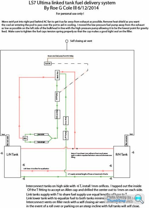
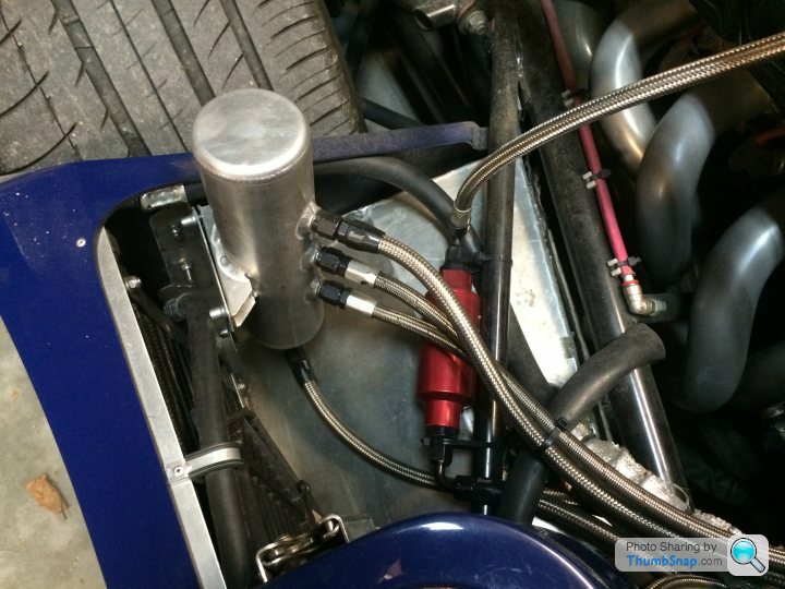
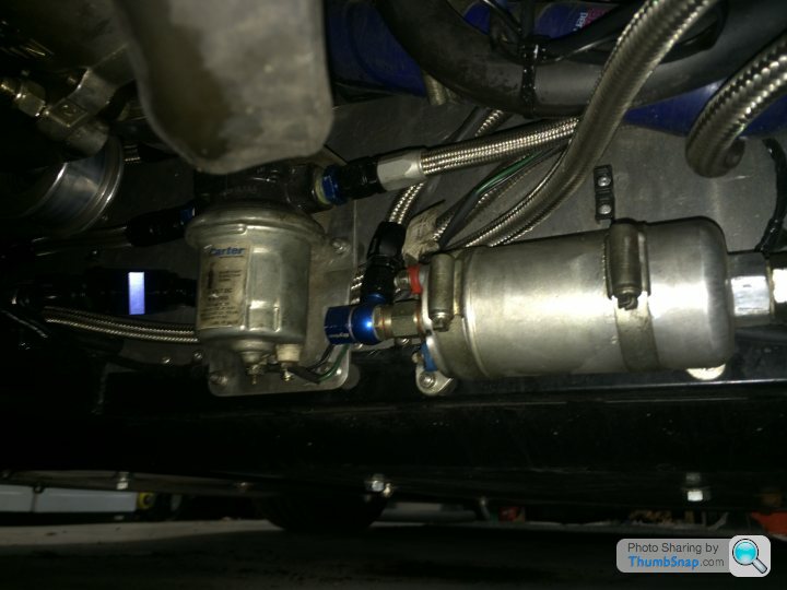
I have experimented with a few ideas and finally came up with a very good solution for the linked tanks. I wanted to test it for several weeks to be sure it was bullet proof. I moved the low pressure pump away from the exhaust and placed it next to the high pressure pump as low as possible to allow the tanks to gravity feed into it. I used 2 equal lengths of fuel line T in to the LP pump to allow near exact draw from each tank. The 2nd set of lower lines became the link to allow for added equalization. As the factory fittings are all -6 this also minimizes sloshing. you effectively create a -12 link at the bottom as you have interconnected both pairs of - 6 fittings. It is important to install orifices in the return T as mentioned by someone prior in this post. I tried it with out however this will cause overfilling to on or the other tanks as the fuel will seek the path of least resistance. I interconnected the filler neck overflows to create vents, using a T and a self closing air valve will allow air to enter the system but will close if fuel is present effectively venting the system. This was mounted up high on the bulkhead. The swirl pot was removed from its location right next to the headers and relocated into the RH side pod behind the AC condenser fan. There was plenty of room there for it and fabricating a bracket was very simple. I removed the heat shield from it as it is far away from the header and you really want the cool air to remove as much heat from the aluminum pot as possible. I also removed the AS fuel rail and installed a larger billet FAST fuel rail. You simply remove the injector spacers and it bolts right on. The LS7 cover will work if you add 3/4" rods to the top of the FAST rails as well! Fuel is fed via the HP pump in to both larger fuel rails at the same time as it is now T at the rear of the fuel rails, the fuel then exists the fuel rails and enters the left and right port of the fuel regulator (this is actually how the regulator should be installed for the LS7 engine) and the return port is T into the top tank link with 1mm orifices. I also installed quick disconnect fittings on the left and right side of the coarse filter on the bulkhead so there is no need to drain the tanks to change the filter element. The fine filter was relocated into the RH side pod and is in line just before the fuel rails. I also added a fuel pressure gauge in the cockpit to monitor pressure. If pressure starts to fall its time to clean or replace the filter elements. 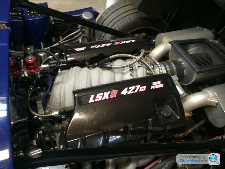
Storer said:
I wouldn't know how to do a diagram on here so a description is all I can offer. I can do a pic or two but they do not show flow.
Two pipes linking bottom of both tanks.
Fuel pumped from inside the l/h tank (sat in the seat or your driver side) using a Aeromotive submersible pump fitted (tightly) into the fuel level sender pipe.
LP pump feeds into the swirl pot (I lied earlier due to wine) all mounted above the l/h tank.
From swirl pot to A1000 h/p pump and then through the fine filter (coarse one on l/p/pump).
From filter to fuel rail (side of engine).
From fuel rail (at pulley end after removing 'valve') to regulator.
From regulator back to swirl pot (2/3 way up pot).
From swirl pot top through restrictor to l/h tank.
Job done.
Fuel pressure sensor is in the regulator.
Hope this helps.
Paul
Paul, Two pipes linking bottom of both tanks.
Fuel pumped from inside the l/h tank (sat in the seat or your driver side) using a Aeromotive submersible pump fitted (tightly) into the fuel level sender pipe.
LP pump feeds into the swirl pot (I lied earlier due to wine) all mounted above the l/h tank.
From swirl pot to A1000 h/p pump and then through the fine filter (coarse one on l/p/pump).
From filter to fuel rail (side of engine).
From fuel rail (at pulley end after removing 'valve') to regulator.
From regulator back to swirl pot (2/3 way up pot).
From swirl pot top through restrictor to l/h tank.
Job done.
Fuel pressure sensor is in the regulator.
Hope this helps.
Paul
What is the theory/benefit to having the filters after the pumps? If I were to place the fine filter before the LP pump, would it not protect both pumps quite effectively? Is your filter placement designed solely to ensure no debris clogs the injectors?
Best,
B.
Gassing Station | Ultima | Top of Page | What's New | My Stuff