Canopy warning kit
Discussion


Steve_D said:
In that case you simply remove the latch, fit the switch bracket behind it and refit.
Your build manual disc includes instructions for this in a separate folder.
Steve
Unfortunately I don't have the build CD (car purchased post build) Your build manual disc includes instructions for this in a separate folder.
Steve
 , which was why I'd asked to see a photo of the switch in situ.
 Here you go then
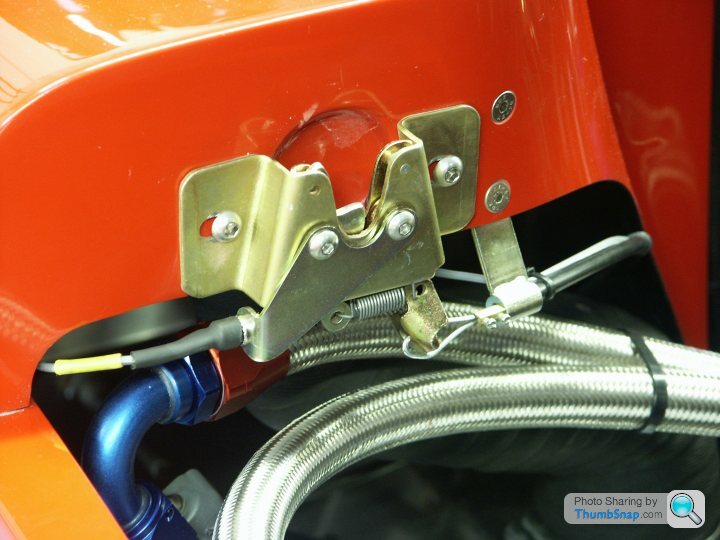

1/ Route cable through side pod on driver’s side (LHD or RHD).
2/ Drill through at rear to accept grommet, if required.
3/ oin in cables should be level with bulkhead.
4/ Route cable across rear bulkhead and secure with cable ties.
5/ Attach switches to their brackets then fit the assemblies to the rear latches.
6/ Ensure that the latches operate correctly. Adjust bracket position if required.
7/ Cut clearance holes in rear canopy.
8/ Drill dashboard to accept the LED’s (8mm). Bezel fits from front, then LED pushes in from rear.
Note: The switch marked with coloured tape corresponds to the LED on that side, similarly marked.
9/ Attach black earth lead and green power lead to the fuel gauge.
10/ Secure wiring with cable ties.
11/ Turn on ignition to check operation.
All stolen from the build manual. Perhaps Ted will forgive me...we will see.
Steve
Very important to cut opening in the rear clam or you may cut the cable when you close it. If its not obvious where to do this let me know and I can send a photo of the cut. I fitted the kit very late in my build and it was pretty straightforward. And on 1 occasion (at least) I do remember them flashing - so may have saved me a lot of money!
I have been trying to upload photos but must have some sort of virus device as nothing is happening. However my photos look totally identical to those posted (which is a good sign!)
Mark
I have been trying to upload photos but must have some sort of virus device as nothing is happening. However my photos look totally identical to those posted (which is a good sign!)
Mark

 t) shirt.
Steve_D said:
Here you go then
1/ Route cable through side pod on driver’s side (LHD or RHD).
2/ Drill through at rear to accept grommet, if required.
3/ oin in cables should be level with bulkhead.
4/ Route cable across rear bulkhead and secure with cable ties.
5/ Attach switches to their brackets then fit the assemblies to the rear latches.
6/ Ensure that the latches operate correctly. Adjust bracket position if required.
7/ Cut clearance holes in rear canopy.
8/ Drill dashboard to accept the LED’s (8mm). Bezel fits from front, then LED pushes in from rear.
Note: The switch marked with coloured tape corresponds to the LED on that side, similarly marked.
9/ Attach black earth lead and green power lead to the fuel gauge.
10/ Secure wiring with cable ties.
11/ Turn on ignition to check operation.
All stolen from the build manual. Perhaps Ted will forgive me...we will see.
Steve
Thanks Steve 1/ Route cable through side pod on driver’s side (LHD or RHD).
2/ Drill through at rear to accept grommet, if required.
3/ oin in cables should be level with bulkhead.
4/ Route cable across rear bulkhead and secure with cable ties.
5/ Attach switches to their brackets then fit the assemblies to the rear latches.
6/ Ensure that the latches operate correctly. Adjust bracket position if required.
7/ Cut clearance holes in rear canopy.
8/ Drill dashboard to accept the LED’s (8mm). Bezel fits from front, then LED pushes in from rear.
Note: The switch marked with coloured tape corresponds to the LED on that side, similarly marked.
9/ Attach black earth lead and green power lead to the fuel gauge.
10/ Secure wiring with cable ties.
11/ Turn on ignition to check operation.
All stolen from the build manual. Perhaps Ted will forgive me...we will see.
Steve

The instructions have been expanded a little from my old copy of the build


So ... After hearing all the stories, I bought myself the warning kit.... Good job it was still sitting in my study when I joined the 'Dumb ass forgot to check his rear clip was engaged properly before he drove off' club - Idiot...
Thankfully, I caught it quickly with only minor damage, Already had the gelcoat on order to sort a few other blemishes anyway.....
So lessons learnt here.... dont just order the kit.... fit it!
Thankfully, I caught it quickly with only minor damage, Already had the gelcoat on order to sort a few other blemishes anyway.....
So lessons learnt here.... dont just order the kit.... fit it!
Gassing Station | Ultima | Top of Page | What's New | My Stuff