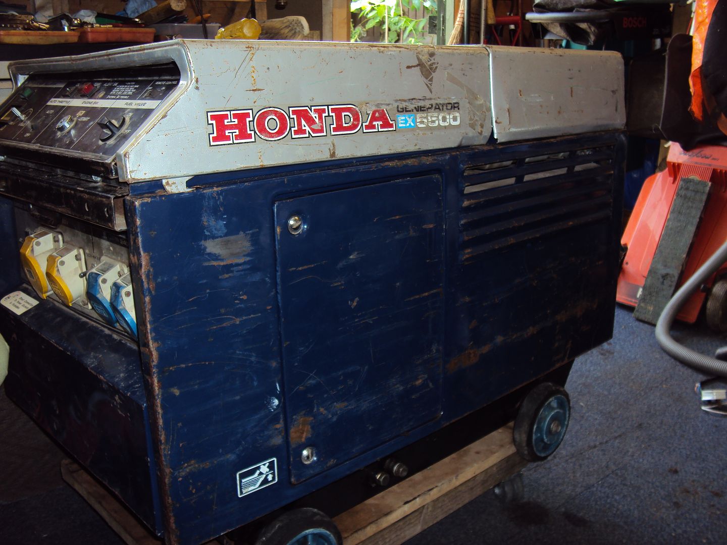
The ebay generator restoration thread
Discussion


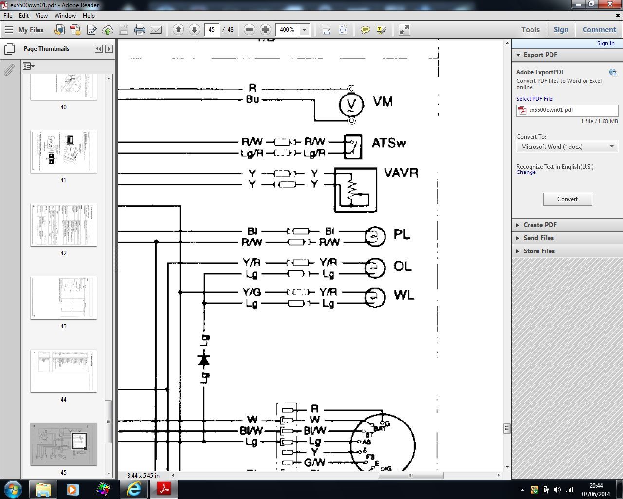
You've definitely wired the pot wrong - the adjustable output is the middle pin. You've got it wired across the fixed resistor - the bit that never changes!
Also, you might want to look at a better pot than that. It isn't really protected against moisture or dirt ingress. Have look for a wire wound type -they will be better sealed and not much more expensive.
Also, you might want to look at a better pot than that. It isn't really protected against moisture or dirt ingress. Have look for a wire wound type -they will be better sealed and not much more expensive.
LordLoveLength said:
You've definitely wired the pot wrong - the adjustable output is the middle pin. You've got it wired across the fixed resistor - the bit that never changes!
Also, you might want to look at a better pot than that. It isn't really protected against moisture or dirt ingress. Have look for a wire wound type -they will be better sealed and not much more expensive.
It's connected as per Honda's wiring diagram, the photo doesn't show that there is a link between the wiper and one end of the fixed resistor.Also, you might want to look at a better pot than that. It isn't really protected against moisture or dirt ingress. Have look for a wire wound type -they will be better sealed and not much more expensive.
Hopefully dirt shouldn't be a problem as the control panel is sealed.
I had noticed one mistake when I tested the alternator output, I forgot to plug the control panel into the alternator so the adjuster wasn't connected which is probably why the O/P was a bit high.
Tomorrow I'm going to assemble more of the case so I can do a load test.

LordLoveLength said:
Ah! Couldn't see that from the photo!
I just can't believe Honda want £60. I'm in the wrong game.
Yep I couldn't believe the prices either! I need to get replacement lenses for the warning lights, however they can only be bought complete with the lamp holder which are £29 each! Been looking at panel mounting LED's, just need to find one to fit a 16mm hole as most are 10/12mm. I just can't believe Honda want £60. I'm in the wrong game.
Edited by Blue32 on Saturday 7th June 22:00
That is a Sewerage works in Minworth. The engines run off gas, which they get for free from our waste. The heat of the exhaust heats the waste up so more gas is produced. The electricity is then sold back to the grid. Pretty clever. I was working there once and the engine next to me back fired and shot a 10 foot flame out of the explosion doors on the exhaust. Safe to say it made me jump!
We also had the same version of engine in the workshop but a V16 for a re build after it threw a con rod through the side. That made a mess!
We also had the same version of engine in the workshop but a V16 for a re build after it threw a con rod through the side. That made a mess!
keo said:
Spark plugs they run on gas. Anyway sorry for the hi jack OP
Sure he won't mind , I will just stop helping him if he complains (happens to be my son  )he is the electronic brains , I lend a hand on disassembling and rebuild if he requires ,also logistics , these thing are a bit big for a car boot , so my van comes in handy
 Edited by MX51ROD on Sunday 8th June 08:36
Dear B,
One other thing to be aware of is power. Once you've got it wired right does the pot get hot?
If it does you might want to consider a chunkier part,
regards,
Jet
Blue32 said:
It's connected as per Honda's wiring diagram, the photo doesn't show that there is a link between the wiper and one end of the fixed resistor.
Hopefully dirt shouldn't be a problem as the control panel is sealed.
I had noticed one mistake when I tested the alternator output, I forgot to plug the control panel into the alternator so the adjuster wasn't connected which is probably why the O/P was a bit high.
Tomorrow I'm going to assemble more of the case so I can do a load test.
The pot you have is likely to be different from the one in the diagram. You need to make the link shown in the diagram 'twixt wiper and one end. What you currently have is an expensive, fixed 400ohm resistor (although unconnected as you say)! As if the pot is permanently at one end of its travel. When you do connect the panel with pot as currently wired I would expect the voltage to drop a bit but still be high and not to vary as you turn the pot. Linking one end and wiper will give you the variable resistance you need.Hopefully dirt shouldn't be a problem as the control panel is sealed.
I had noticed one mistake when I tested the alternator output, I forgot to plug the control panel into the alternator so the adjuster wasn't connected which is probably why the O/P was a bit high.
Tomorrow I'm going to assemble more of the case so I can do a load test.
One other thing to be aware of is power. Once you've got it wired right does the pot get hot?
If it does you might want to consider a chunkier part,
regards,
Jet
jet_noise said:
Blue32 said:
the photo doesn't show that there is a link between the wiper and one end of the fixed resistor.
You need to make the link shown in the diagram 'twixt wiper and one end. Linking one end and wiper will give you the variable resistance you need.keo said:
Spark plugs they run on gas. Anyway sorry for the hi jack OP
No problem  they look like fun to work on. Don't think I could fit one in the garden shed to play with though
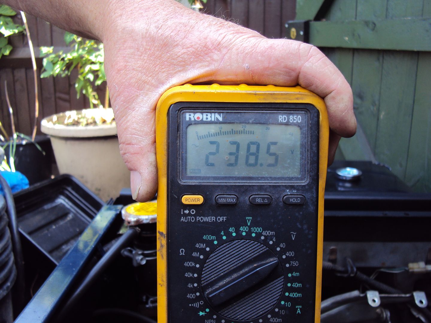
Load test passed and voltage adjuster working
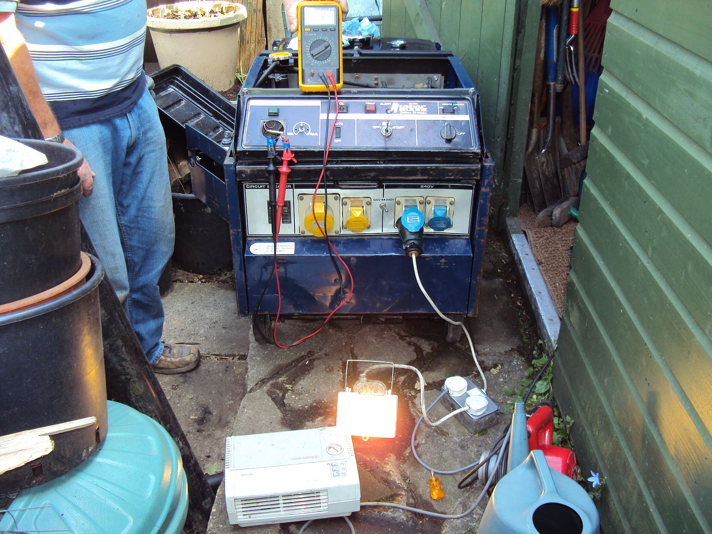
Loaded up with 2x 2000W fan heaters
Running with 2000w fan heater + 120w flood light
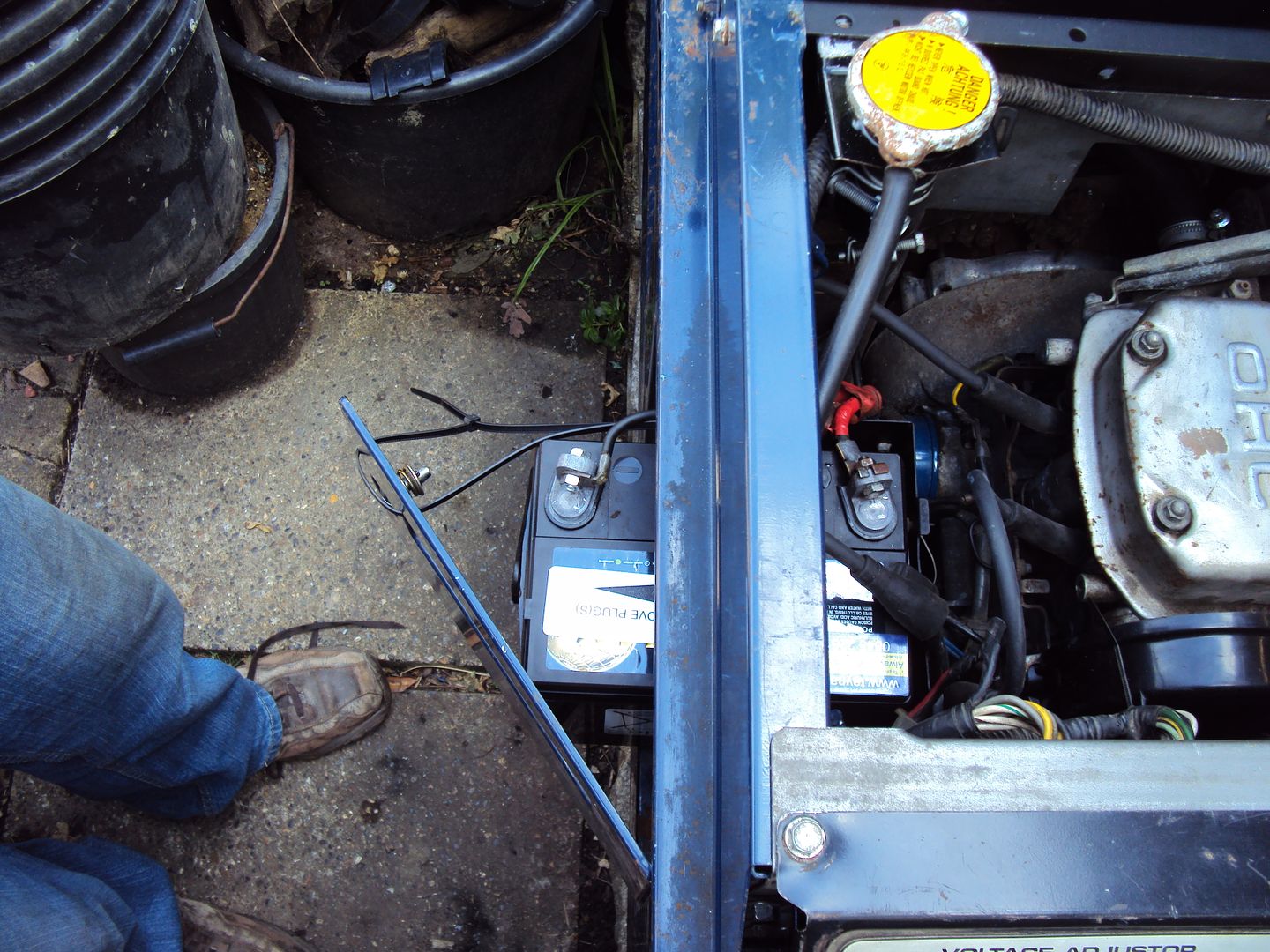
I need to extend the battery leads as the + lead wouldn't reach the terminal, so had to reposition the battery and do a temp lash up with some zip ties to the battery in place so the lead would reach.
During the test we found a small leak in the radiator end tank, so either need to put some radweld in, or find someone to braze it up.
Also need to source a replacement volt meter as it is missing and buy a proper key as my home made key is starting to bend a bit.

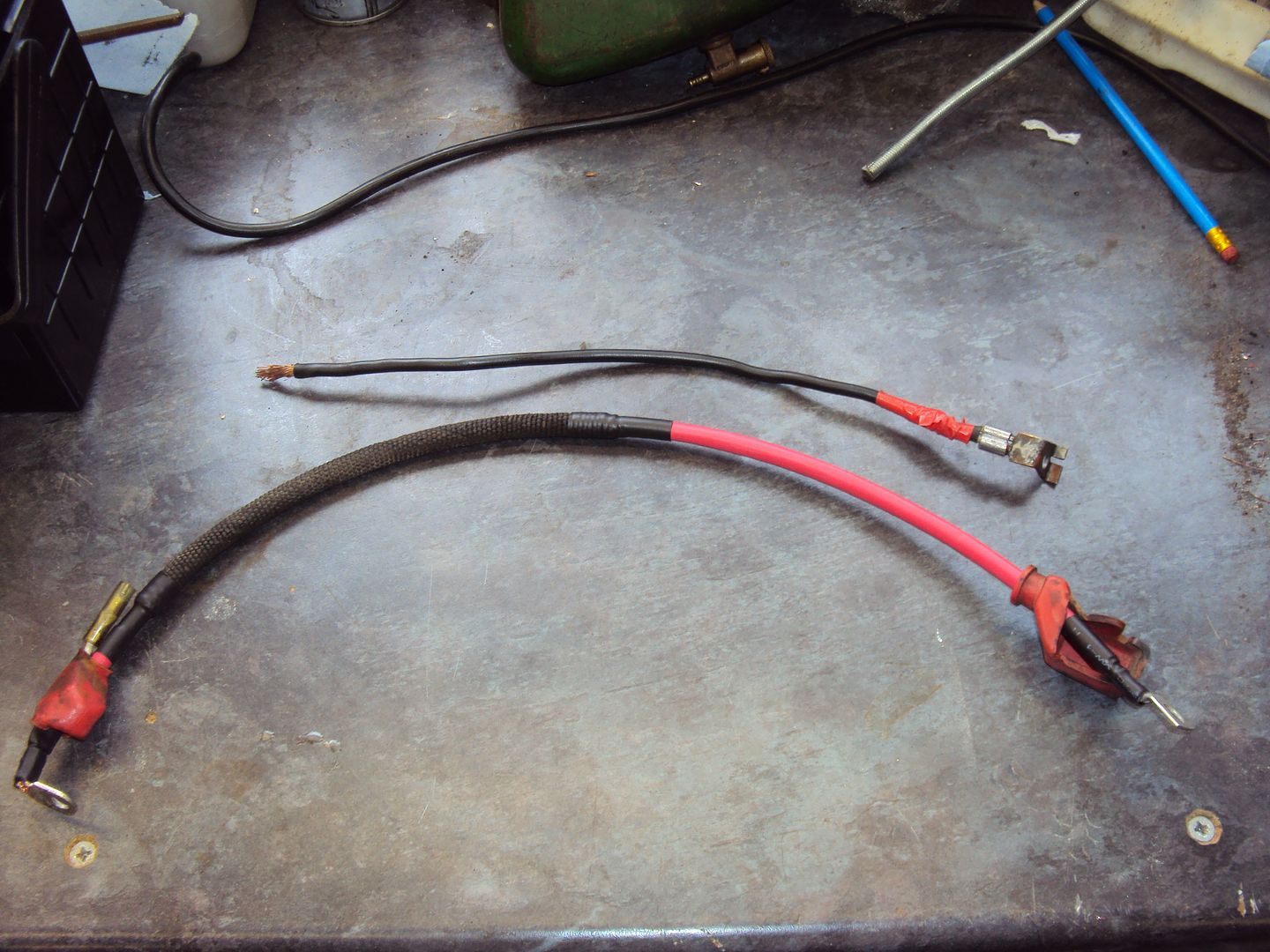
I have made a new cable to go from the battery to the starter motor, the new cable is 10-15cm longer so it can reach the battery terminal.
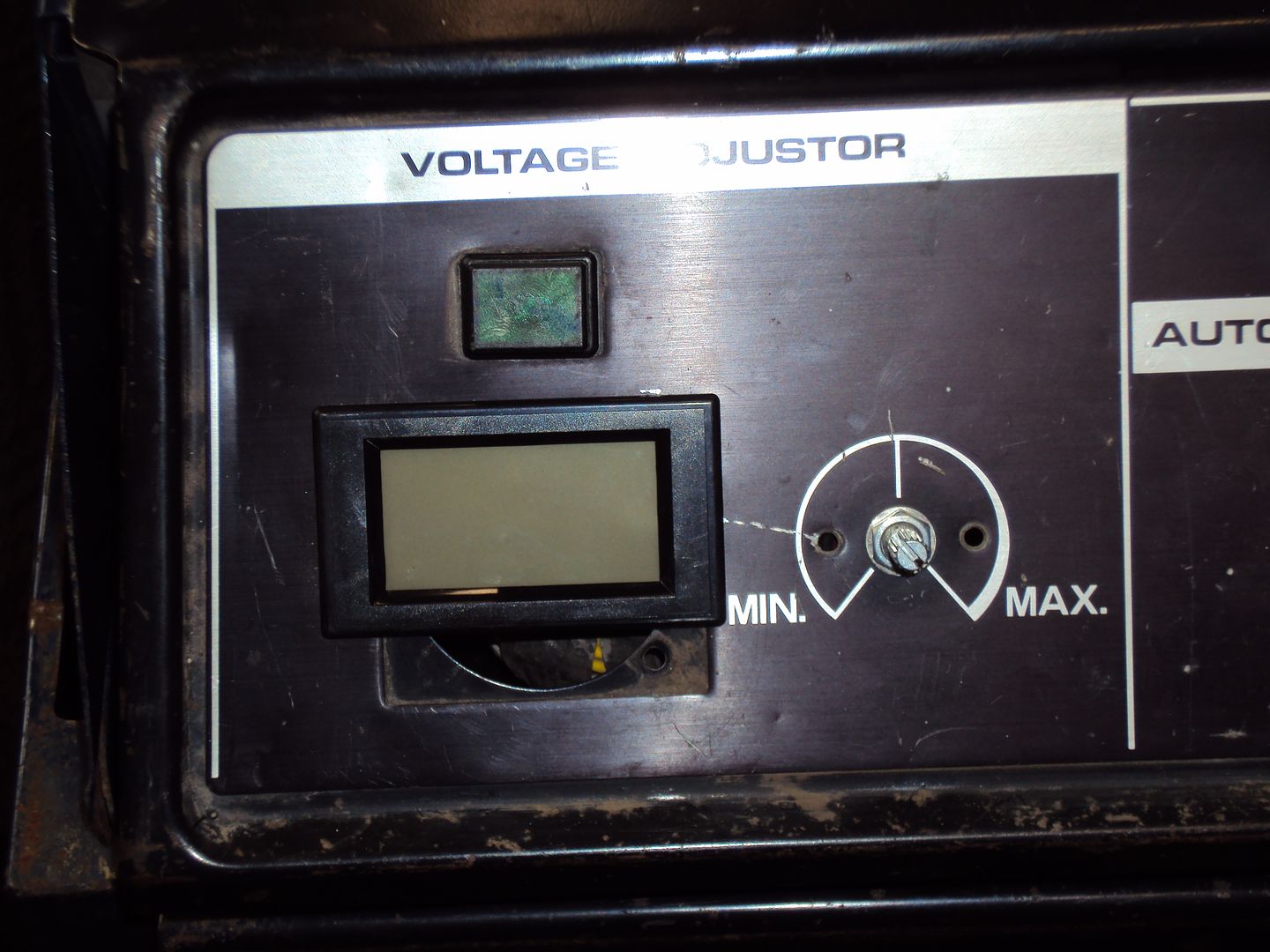
The original volt meter was analogue, I decided to replace it with a digital meter as it would be easier to monitor the voltage, the meter also displays the current being drawn.
Meter cut into front panel, just need to make a cover to go over the remainder of the hole for the old meter.
The original volt meter was analogue, I decided to replace it with a digital meter as it would be easier to monitor the voltage, the meter also displays the current being drawn.
Meter cut into front panel, just need to make a cover to go over the remainder of the hole for the old meter.
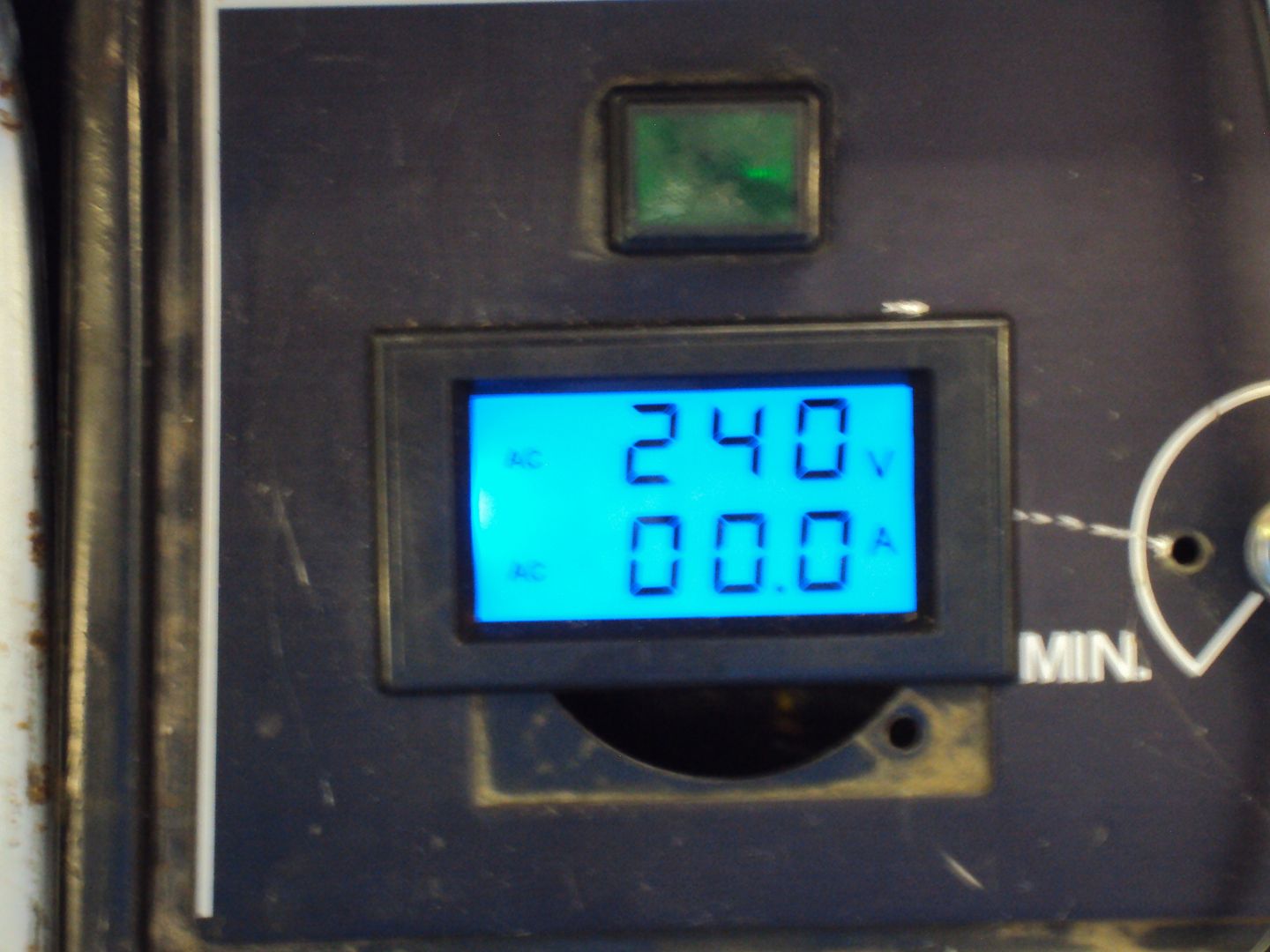
Digital voltage/current meter now wired up and working
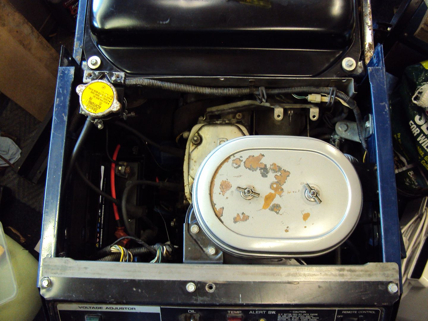
I have now got everything re-assembled, just need 10 bolts replaced as they were stripped.
Air filter reattached
Now for the real geaky bit

I wanted to check the output frequency, I started by looking at the incoming mains to the man cave (AKA garden shed ) with an oscilloscope
Unfortunately I don’t have a nice digital scope which works everything out, so have to do it the old way.
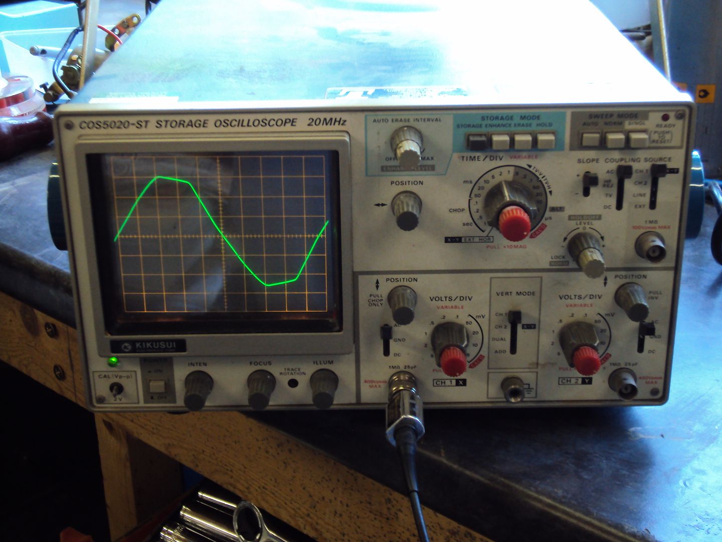
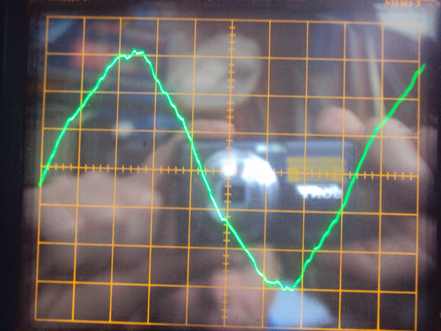
To calculate the frequency I use the formula F= 1/T where T is the time base of the oscilloscope. To measure the frequency the number of divisions for 1 cycle are counted and are used to multiply the time base setting.
For the incoming mains* the time base was set at 2ms, one cycle was 9.8 divisions which gives 19.6ms (9.8*2ms) giving a frequency of 51.02Hz. Guess I need to get the oscilloscope calibrated…
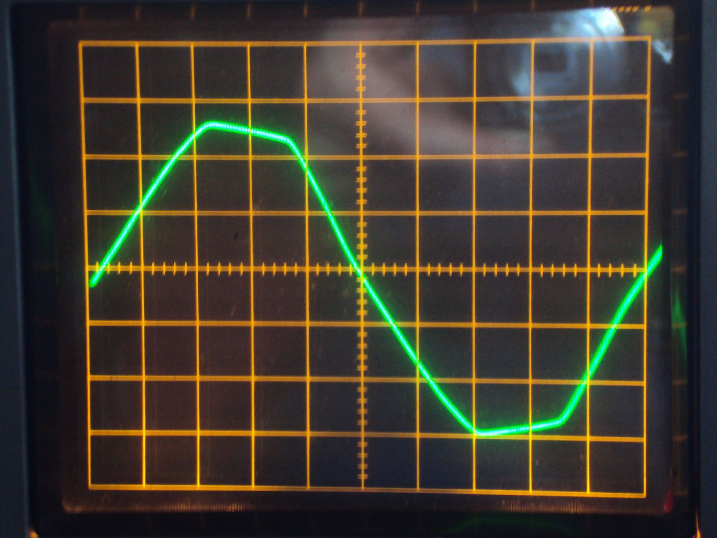
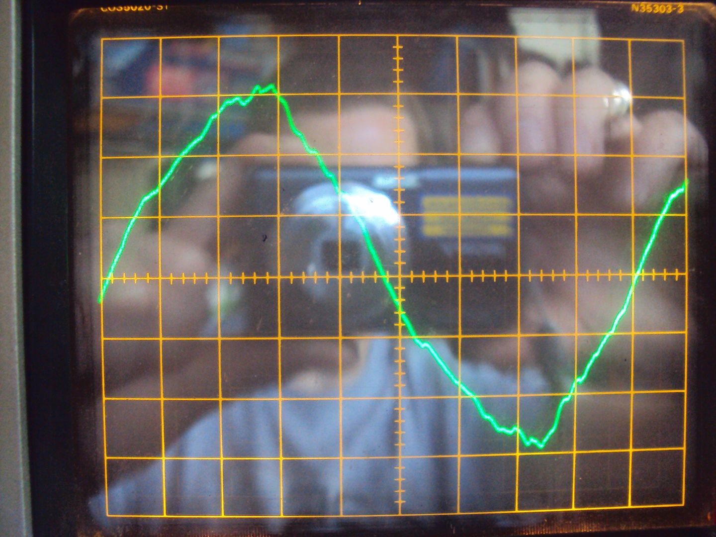
Frequency = 8.4*2 =16.8ms = 59.52Hz
The generator can be set for 50Hz or 60Hz by moving a spring between 2 positions on the governor, so it looks like I put the spring in the wrong position during reassembly.
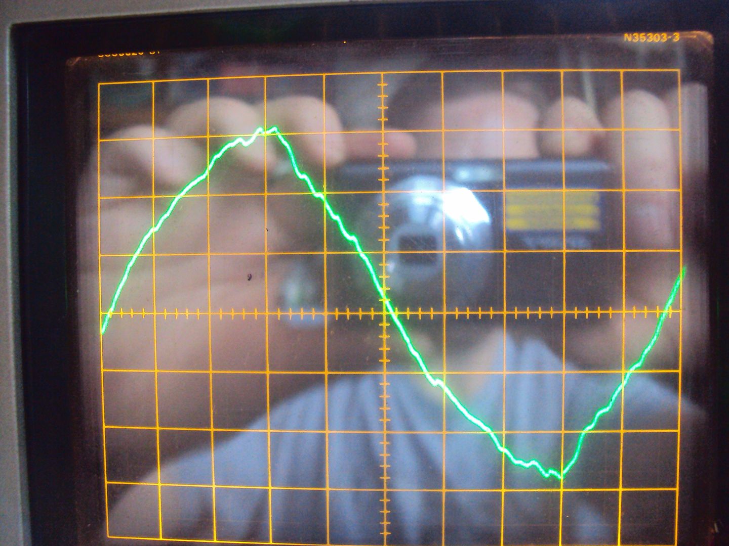
With the spring moved to the lower position on the governor arm.
Getting there 54.34Hz
Final adjustments are made using a screw which alters the tension on the governor spring, so after a bit of adjustment:
A reasonably stable 50Hz
Not bad for a mechanical control.
I have now got everything re-assembled, just need 10 bolts replaced as they were stripped.
Air filter reattached
Now for the real geaky bit
I wanted to check the output frequency, I started by looking at the incoming mains to the man cave (AKA garden shed
) with an oscilloscope Unfortunately I don’t have a nice digital scope which works everything out, so have to do it the old way.
To calculate the frequency I use the formula F= 1/T where T is the time base of the oscilloscope. To measure the frequency the number of divisions for 1 cycle are counted and are used to multiply the time base setting.
For the incoming mains* the time base was set at 2ms, one cycle was 9.8 divisions which gives 19.6ms (9.8*2ms) giving a frequency of 51.02Hz. Guess I need to get the oscilloscope calibrated…
- NOTE I did NOT connect the oscilloscope directly to the mains, the measurements were made via a transformer to drop the voltage to a safe level.
Frequency = 8.4*2 =16.8ms = 59.52Hz
The generator can be set for 50Hz or 60Hz by moving a spring between 2 positions on the governor, so it looks like I put the spring in the wrong position during reassembly.
With the spring moved to the lower position on the governor arm.
Getting there 54.34Hz
Final adjustments are made using a screw which alters the tension on the governor spring, so after a bit of adjustment:
A reasonably stable 50Hz
Not bad for a mechanical control.
Gassing Station | Homes, Gardens and DIY | Top of Page | What's New | My Stuff