Amateur seismology anyone?
Discussion


Thought I'd share a little project I started last week, that I started through a combination of procrastination and having taken a few days break in between writing vast chunks of my thesis. Once the word count hit multiples of 10,000 things got a little hazy and I needed a break! Anyway, when I write I find that having things like Attenborough documentaries and the like playing in the background a bit soothing. But last week I watched a series of geology programs by Iain Stewart on volcanoes, Earthquakes etc. So in a fit of procrastination I started reading about seismology and saw that you can build a fairly respectable instrument to measure seismic events quite easily...
This is probably the start of a slippery slope, this is how I got into aero-engineering way back in the summer of 1996 after seeing a documentary on Sir Frank Whittle and ended up building a rudimentary jet engine a few months later. Later that year I ended up with a D in my maths GCSE exam and became a welder. Well I'm now about to finish a PhD in engineering, certainly never thought I'd end up on this path. But I've always had the urge to build things and enjoy the challenge of learning all about a subject, understanding the theory and then putting it into practice.
So anyway back on topic, these seismometers - how hard can they be? Well not very. Turns out that in principle all you need to do is suspend a magnet over a wire coil, and measure the voltage as the magnet moves and hey ho, you're there. But as usual the devil is in the details, the voltages produced by the coil are on the order of millivolts (thousandths of a Volt) so you need an amplifier. The wire coil and amplification circuitry also requires noise filtering, as very small levels of electrical noise picked up by the coil would also then be amplified. The apparatus holding the magnet must be tuned to the frequencies of typical seismic events and the list goes on.
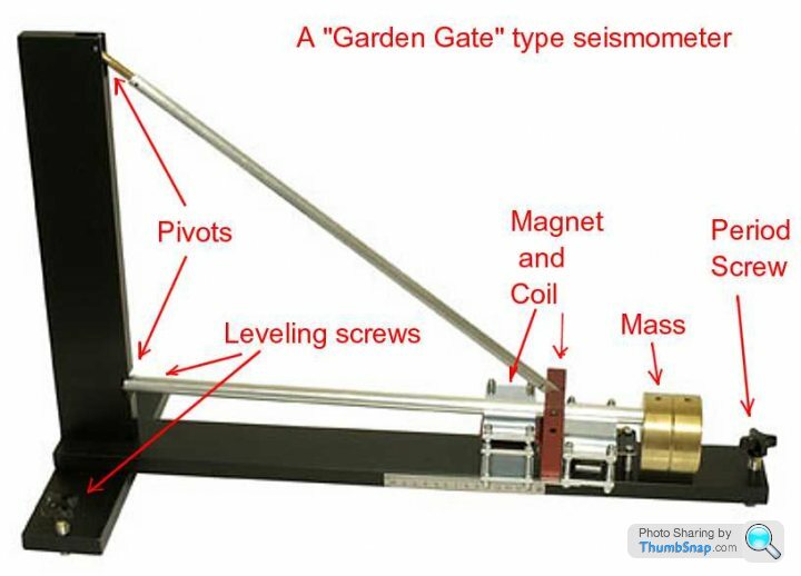
So anyway a trawl through Google later and I found a simple design consisting of a hinged arm holding the magnet above a coil and held by a spring with some magnetic damping. This design only measures a single axis and in this arrangement it only senses the vertical components. But it looks like some simple modifications will see it measuring lateral and longitudinal axes, albeit with the need to have an instrument per axis. Once my thesis is out of the way I'd like to revisit this and see if I can design an instrument to measure the three axes in one go, theoretically I should then be able to determine the direction of any sesimic activity. If I had more than one seismometer then you can locate the origin, but I need to do some more reading on this.
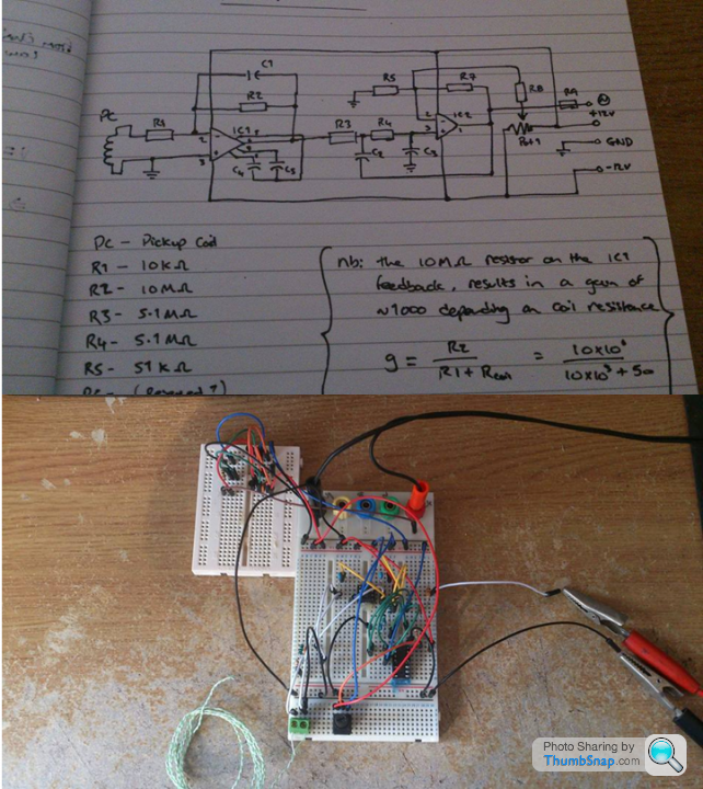
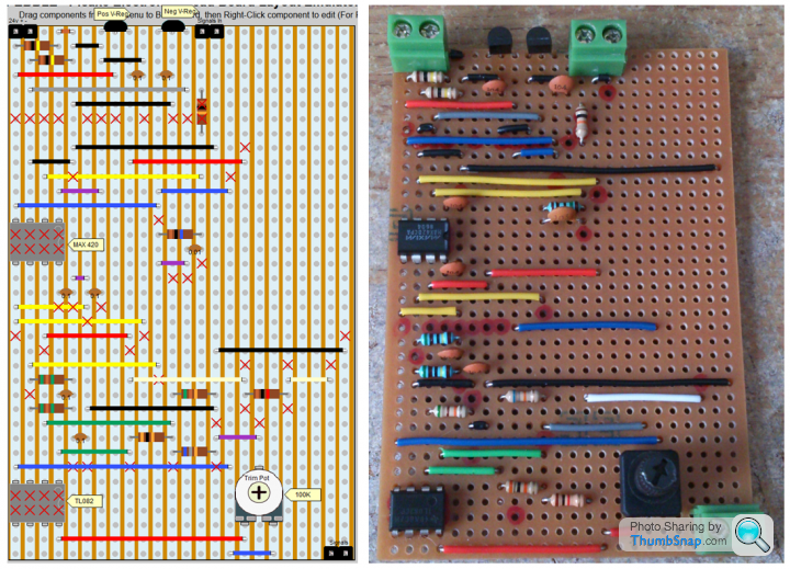
So to deal with the tiny Voltages created by the coil we need to amplify them. The amplifier circuit consists of two parts, the first half amplifies the signal to +/-10 Volts and the second filters out unwanted noise to give a clean signal. The circuit diagram on the top half of the picture below is what's on the breadboard underneath. The second breadboard on the top left simply takes a 24V DC power supply (about £5 from Ebay) and splits it into +/- 12V for the amplifier. I plugged in a small thermocouple for testing as this generates millivolt signals too and I hadn't yet wound the coil, more on that shortly. I've only got as far as prototyping this circuit as I need to check out the noise filtering with an oscilloscope and tidy things up a little before I feel confident enough to transfer it to some stripboard.
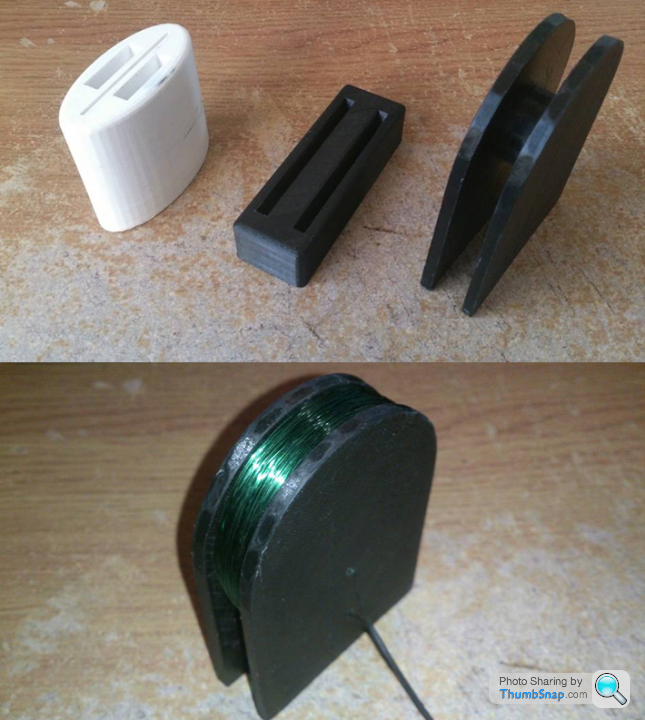
Our engineering dept at Liverpool Uni gives us free access to a few 3D printers and I've used these in past for all sorts of things, from helping third year's with their student projects to making things for my RC aircraft and fixing a cup holder for a car. So rather than waste time making things like the spool for the wire coil and the magnetic damper, I created some parts using CAD software and had them printing within ten minutes. The beauty of this is that I know the parts will fit together perfectly and saves me a lot of time which can go into writing more of my thesis.....Ahem.... The white part is the magnetic damper which will hold a couple of neodymium magnets at a set distance from a thin copper blade which will reside in the thin, central slot. As the blade moves through the magnetic field it creates a current which in turn creates it's own magnetic field, resisting the movement of the copper blade which is attached to the arm and therefore providing some damping on the system. The three black parts simply slot together to form a combined spool and stand which was then wound with 1400 turns of 0.25mm enamelled copper wire to give a total length of 400m. These numbers were based on some estimates I made using my rusty electromagnetic knowledge, a few books and some helpful websites to find the internal and external diameters of the coil, estimate the change of the inductor flux over time, estimated coil resistance etc. so I erred for a total wire length a bit longer and then I can trim the length if necessary. As it happens it seems to perform ok, I measured a total resistance of 94 Ohms for the coil (estimated 100 Ohms) and moving a large horseshoe magnet over the coil saturates my amplifier (image below). This is promising as I assume any seismic event will be many times less than my ham fisted attempts at moving the magnet.
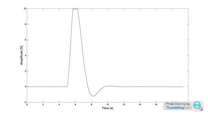
The Matlab plot below is of the raw, amplified Voltage signal generated by the coil after I very quickly lifted a horseshoe magnet off the coil, that had been resting there for a minute to allow any Voltage created to die away to see what the data looked like before proceeding. I'll apply some more post-processing filtering on the signals once I've built everything, as I'm worried that things like footfalls, heavy traffic and the like might register as false positives. But as the frequencies of this background noise will be much higher than seismic events I'm not too worried yet, the signal below seems well damped as it stands so again, things look promising.
That's as far as I've got with the physical aspects of the seismometer. I've done some simple calculations on the beam sizing to investigate things like spring constants and the mass at the end of the arm. But I think it will still need some tuning once built and I'd like to have that functionality in from the start such as doing some more 3D printing to build a movable tuning mass at the end of the arm. I've also built a needlessly pretty, executable program using Labview which will constantly measure the signals, writing them to a text file and then email me with a picture of a waveform should it detect a seismic event while I'm not around. I did say I procrastinate wildly didn't I. But I figured that the odds of me turning it on and measuring something are going to be tiny, also I wanted it to be running at all times so I didn't want to have to keep monitoring it daily to see if anything had happened. So the plan is to cannibalise an old SSD notebook and have that doing the work, recording 24/7 as it doesn't draw a lot of power and will let me know with periodic updates on it's status and alerts should anything happen. I'll update on the program and further details if anyone is interested. Just seemed like an interesting thing to do other than write another 10,000 words on ship aerodynamics...
This is probably the start of a slippery slope, this is how I got into aero-engineering way back in the summer of 1996 after seeing a documentary on Sir Frank Whittle and ended up building a rudimentary jet engine a few months later. Later that year I ended up with a D in my maths GCSE exam and became a welder. Well I'm now about to finish a PhD in engineering, certainly never thought I'd end up on this path. But I've always had the urge to build things and enjoy the challenge of learning all about a subject, understanding the theory and then putting it into practice.
So anyway back on topic, these seismometers - how hard can they be? Well not very. Turns out that in principle all you need to do is suspend a magnet over a wire coil, and measure the voltage as the magnet moves and hey ho, you're there. But as usual the devil is in the details, the voltages produced by the coil are on the order of millivolts (thousandths of a Volt) so you need an amplifier. The wire coil and amplification circuitry also requires noise filtering, as very small levels of electrical noise picked up by the coil would also then be amplified. The apparatus holding the magnet must be tuned to the frequencies of typical seismic events and the list goes on.
So anyway a trawl through Google later and I found a simple design consisting of a hinged arm holding the magnet above a coil and held by a spring with some magnetic damping. This design only measures a single axis and in this arrangement it only senses the vertical components. But it looks like some simple modifications will see it measuring lateral and longitudinal axes, albeit with the need to have an instrument per axis. Once my thesis is out of the way I'd like to revisit this and see if I can design an instrument to measure the three axes in one go, theoretically I should then be able to determine the direction of any sesimic activity. If I had more than one seismometer then you can locate the origin, but I need to do some more reading on this.
So to deal with the tiny Voltages created by the coil we need to amplify them. The amplifier circuit consists of two parts, the first half amplifies the signal to +/-10 Volts and the second filters out unwanted noise to give a clean signal. The circuit diagram on the top half of the picture below is what's on the breadboard underneath. The second breadboard on the top left simply takes a 24V DC power supply (about £5 from Ebay) and splits it into +/- 12V for the amplifier. I plugged in a small thermocouple for testing as this generates millivolt signals too and I hadn't yet wound the coil, more on that shortly. I've only got as far as prototyping this circuit as I need to check out the noise filtering with an oscilloscope and tidy things up a little before I feel confident enough to transfer it to some stripboard.
Our engineering dept at Liverpool Uni gives us free access to a few 3D printers and I've used these in past for all sorts of things, from helping third year's with their student projects to making things for my RC aircraft and fixing a cup holder for a car. So rather than waste time making things like the spool for the wire coil and the magnetic damper, I created some parts using CAD software and had them printing within ten minutes. The beauty of this is that I know the parts will fit together perfectly and saves me a lot of time which can go into writing more of my thesis.....Ahem.... The white part is the magnetic damper which will hold a couple of neodymium magnets at a set distance from a thin copper blade which will reside in the thin, central slot. As the blade moves through the magnetic field it creates a current which in turn creates it's own magnetic field, resisting the movement of the copper blade which is attached to the arm and therefore providing some damping on the system. The three black parts simply slot together to form a combined spool and stand which was then wound with 1400 turns of 0.25mm enamelled copper wire to give a total length of 400m. These numbers were based on some estimates I made using my rusty electromagnetic knowledge, a few books and some helpful websites to find the internal and external diameters of the coil, estimate the change of the inductor flux over time, estimated coil resistance etc. so I erred for a total wire length a bit longer and then I can trim the length if necessary. As it happens it seems to perform ok, I measured a total resistance of 94 Ohms for the coil (estimated 100 Ohms) and moving a large horseshoe magnet over the coil saturates my amplifier (image below). This is promising as I assume any seismic event will be many times less than my ham fisted attempts at moving the magnet.
The Matlab plot below is of the raw, amplified Voltage signal generated by the coil after I very quickly lifted a horseshoe magnet off the coil, that had been resting there for a minute to allow any Voltage created to die away to see what the data looked like before proceeding. I'll apply some more post-processing filtering on the signals once I've built everything, as I'm worried that things like footfalls, heavy traffic and the like might register as false positives. But as the frequencies of this background noise will be much higher than seismic events I'm not too worried yet, the signal below seems well damped as it stands so again, things look promising.
That's as far as I've got with the physical aspects of the seismometer. I've done some simple calculations on the beam sizing to investigate things like spring constants and the mass at the end of the arm. But I think it will still need some tuning once built and I'd like to have that functionality in from the start such as doing some more 3D printing to build a movable tuning mass at the end of the arm. I've also built a needlessly pretty, executable program using Labview which will constantly measure the signals, writing them to a text file and then email me with a picture of a waveform should it detect a seismic event while I'm not around. I did say I procrastinate wildly didn't I. But I figured that the odds of me turning it on and measuring something are going to be tiny, also I wanted it to be running at all times so I didn't want to have to keep monitoring it daily to see if anything had happened. So the plan is to cannibalise an old SSD notebook and have that doing the work, recording 24/7 as it doesn't draw a lot of power and will let me know with periodic updates on it's status and alerts should anything happen. I'll update on the program and further details if anyone is interested. Just seemed like an interesting thing to do other than write another 10,000 words on ship aerodynamics...
Edited by Fugazi on Tuesday 10th May 23:12
Earthquakes have a quite distinct waveform so it should be fairly easy to separate them out from unwanted background events. The only problem may be if the two occur at the same time. The easiest way would probably be to use one of the live online seismometer sites to correlate your data with.
Monty Python said:
Earthquakes have a quite distinct waveform so it should be fairly easy to separate them out from unwanted background events. The only problem may be if the two occur at the same time. The easiest way would probably be to use one of the live online seismometer sites to correlate your data with.
That's the plan, the British Geological Survey has live updates of activity on their website as do their US counterparts and several other geological research organisations. This was also part of the reason why I wanted to receive real time updates of my system, then I can check those sites and see if they recorded anything. If I do detect anything, then I'm hoping that I can use their data to start to scale my charts to get an idea of the sensitivity of the design. So things haven't progressed as quickly as I would've liked with uni work taking priority at the moment. I have now transferred the circuit from the prototype on the breadboard to some stripboard so that it's a bit more permanent and neater. Also finished the data recording program and tarted it up a bit, not that anybody will see it but there's nothing more soul destroying than a boring, bog standard, grey, Labview interface.
So here's the finished circuit, it will do for now but if I do decide to make a three-axis seismometer I'll probably print and etch a PCB as stripboard circuits can be quite large and I'm sure I could fit three of these circuits onto a PCB of the same size. Anyway for those interested there's a great bit of freeware that I used to locate the various components onto the size of stripboard I was using and to give a sanity check before soldering complex projects.
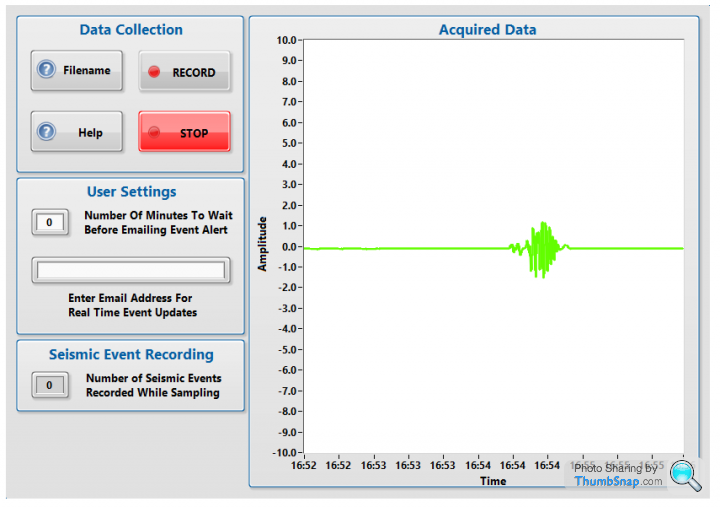
This is the font panel of the software showing a rolling chart of the previous hour's data and options for email address and filepaths for the data but it's all fairly self explanatory. I have let this program and hardware run continuously in the background of my main pc for nearly a week now, with no hiccups. I have begun to wonder whether I could ditch the notebook and a separate DAQ and replace with an Arduino board which has built in analogue DAQ channels and can be bundled into a small project box with the amplifier circuit and make it look a little less Heath-Robinson. It's something to think about for version 2 I suppose, just getting this up and running for now is my main goal. The little squiggle on the chart was me waving a small magnetic screwdriver near the coil during some testing, it's actually remarkably sensitive and will pick up a signal generated from a weak fridge magnet moving a couple of feet away.
All that is left now is to assemble the arm and tune the damping, with any luck it should be up and running by next weekend! There's been several reports of earthquakes recently and it's spurring me on to get it finished as I should be able to pick these up from the otherside of the world.
So here's the finished circuit, it will do for now but if I do decide to make a three-axis seismometer I'll probably print and etch a PCB as stripboard circuits can be quite large and I'm sure I could fit three of these circuits onto a PCB of the same size. Anyway for those interested there's a great bit of freeware that I used to locate the various components onto the size of stripboard I was using and to give a sanity check before soldering complex projects.
This is the font panel of the software showing a rolling chart of the previous hour's data and options for email address and filepaths for the data but it's all fairly self explanatory. I have let this program and hardware run continuously in the background of my main pc for nearly a week now, with no hiccups. I have begun to wonder whether I could ditch the notebook and a separate DAQ and replace with an Arduino board which has built in analogue DAQ channels and can be bundled into a small project box with the amplifier circuit and make it look a little less Heath-Robinson. It's something to think about for version 2 I suppose, just getting this up and running for now is my main goal. The little squiggle on the chart was me waving a small magnetic screwdriver near the coil during some testing, it's actually remarkably sensitive and will pick up a signal generated from a weak fridge magnet moving a couple of feet away.
All that is left now is to assemble the arm and tune the damping, with any luck it should be up and running by next weekend! There's been several reports of earthquakes recently and it's spurring me on to get it finished as I should be able to pick these up from the otherside of the world.
Edited by Fugazi on Monday 23 May 18:05
With fracking on it's way back in the UK, I imagine quite a few people will be getting interested in having seismometers. Are MEMS accelerometers a practical proposition? They often integrate 3-axis sensing in a single chip. They used to be stupidly expensive but since they started being used in phones the price has dropped to the <1$ level. Manufacturers like Analog.com freely hand out samples of this sort of thing to "qualifying individuals", and I'm sure a PhD candidate at a university would definitely qualify! They also provide schematics for tried and tested signal conditioning circuits.
Zad said:
With fracking on it's way back in the UK, I imagine quite a few people will be getting interested in having seismometers. Are MEMS accelerometers a practical proposition? They often integrate 3-axis sensing in a single chip. They used to be stupidly expensive but since they started being used in phones the price has dropped to the <1$ level. Manufacturers like Analog.com freely hand out samples of this sort of thing to "qualifying individuals", and I'm sure a PhD candidate at a university would definitely qualify! They also provide schematics for tried and tested signal conditioning circuits.
I don't think MEMS devices are sensitive enough for seismographic use. If you look at their bandwidth, peak acceleration and dynamic range they're still too pick up tremors.Interesting project! I have seen similar made from loudspeakers - something a few inches across, laid on its back with a small weight attached to the cone.
Any idea if they are as sensitive? maybe an interesting comparison test?
Re the electronics - making things on breadboard is really tedious (as you've no doubt found out..) but the circuit you are using is simple and common.
You should be able to find a mic amp kit or similar that will do the same job for you and has a pcb + layout already done to save you time. It will probably be more stable as well.
Alternatively, there is someone on ebay that does prototype pcbs using a milling machine. Good results, very cheap and you use free layout software. Good luck - keep us updated!
If anyone ever wants to make a PCB there are plenty of cheap fabricators out there. e.g.
http://www.seeedstudio.com/
https://www.itead.cc/open-pcb/pcb-prototyping.html
e.g. 5x 5x5cm single layer PCB, $10.
Using a double sided PCB will help to screen the amplifier from noise, although I guess you will be housing it in a metal case anyway. Had you thought about using a Raspberry Pi to do the logging? Relatively easy to interface, use comparatively little power, and enough oomph to run its own local web site, email daemon, push alerts etc. Cheap GPS modules are available which would allow very precise time correlation.
Zad said:
With fracking on it's way back in the UK, I imagine quite a few people will be getting interested in having seismometers. Are MEMS accelerometers a practical proposition? They often integrate 3-axis sensing in a single chip. They used to be stupidly expensive but since they started being used in phones the price has dropped to the <1$ level. Manufacturers like Analog.com freely hand out samples of this sort of thing to "qualifying individuals", and I'm sure a PhD candidate at a university would definitely qualify! They also provide schematics for tried and tested signal conditioning circuits.
Hadn't thought of that, I'm not far from Liverpool and sat on the edge of Lancashire so I could well pick these small scale things up if they occur. If I remember correctly there were some small disturbances last time fracking was carried out in Lancashire. I looked at those small accelerometers but like MP pointed out, the cheap ones won't be able to detect the kind of amplitudes I'm trying to measure. They are used on high end seismometers, from what I can see on various papers but they're a bit beyond my means and tend to be very expensive as they're more bespoke. I have thought about using strain gauges to measure beam flexure instead of the coil-magnet system here, that way you could design a multi-axis system but that needed a fair bit more work than I can commit to at the moment. Although thanks for the link, I will go have a look at that site as we do use a few accelerometers each year on various projects on the motion-base flight simulators at uni and they could come in handy.LordLoveLength said:
Interesting project! I have seen similar made from loudspeakers - something a few inches across, laid on its back with a small weight attached to the cone.
Any idea if they are as sensitive? maybe an interesting comparison test?
Re the electronics - making things on breadboard is really tedious (as you've no doubt found out..) but the circuit you are using is simple and common.
You should be able to find a mic amp kit or similar that will do the same job for you and has a pcb + layout already done to save you time. It will probably be more stable as well.
Alternatively, there is someone on ebay that does prototype pcbs using a milling machine. Good results, very cheap and you use free layout software. Good luck - keep us updated!
I did see some similar setups using loudspeakers and in essence the one I'm building is more or less the same in operation, I just happened to wind my own coil instead for those extra DIY points Any idea if they are as sensitive? maybe an interesting comparison test?
Re the electronics - making things on breadboard is really tedious (as you've no doubt found out..) but the circuit you are using is simple and common.
You should be able to find a mic amp kit or similar that will do the same job for you and has a pcb + layout already done to save you time. It will probably be more stable as well.
Alternatively, there is someone on ebay that does prototype pcbs using a milling machine. Good results, very cheap and you use free layout software. Good luck - keep us updated!
 I have etched my own PCB's before but as this is a bit of a first attempt just to see what happens I thought stripboard would suffice. I do have a few millivolt amplifiers knocking around already which I normally use for my gas turbine testbeds, but I do like building my own circuits and going through the learning process, plus if it all works I can look at refinements later. It was the same with model aircraft, enjoyed the building far more than the flying.
Zad said:
If anyone ever wants to make a PCB there are plenty of cheap fabricators out there. e.g.
http://www.seeedstudio.com/
https://www.itead.cc/open-pcb/pcb-prototyping.html
e.g. 5x 5x5cm single layer PCB, $10.
Using a double sided PCB will help to screen the amplifier from noise, although I guess you will be housing it in a metal case anyway. Had you thought about using a Raspberry Pi to do the logging? Relatively easy to interface, use comparatively little power, and enough oomph to run its own local web site, email daemon, push alerts etc. Cheap GPS modules are available which would allow very precise time correlation.
Thanks for the link, for some reason I thought milling a PCB would be more expensive for small, one off projects glad to see it's actually quite reasonable. I have thought of using a small, single board computer and did think about using an Arduino simply as I have one sat unused in my office and it has analogue inputs so wouldn't need a separate DAQ, but those features on the Pi do look interesting, definitely an option for the future.http://www.seeedstudio.com/
https://www.itead.cc/open-pcb/pcb-prototyping.html
e.g. 5x 5x5cm single layer PCB, $10.
Using a double sided PCB will help to screen the amplifier from noise, although I guess you will be housing it in a metal case anyway. Had you thought about using a Raspberry Pi to do the logging? Relatively easy to interface, use comparatively little power, and enough oomph to run its own local web site, email daemon, push alerts etc. Cheap GPS modules are available which would allow very precise time correlation.
As for progress, well I haven't had a minute to myself this last week so progress has been nil but I will update soon though.
Id' try to make the sensor reasonably wideband, and then FFT the datastream to identify the spectral energy distribution, which would allow you to "fingerprint" sesmic activity i think! The processing power of even a cheap laptop or PC makes this very easy these days! You'll want to sample WAY faster than the fundamental frequency in any case to get sufficiently "dense" frequency domain bins.
I'm sampling data at 1000Hz and saving it continuously to a text file in timestamped, one hour long chunks, I might even reduce this to 500Hz depending on how fast data starts to accumulate. Off the top of my head, I think most earthquakes have maximum frequencies in the region of 20Hz so 1000Hz sampling rates should be more than enough to do some analysis of the frequency domain. Rather than trying to manipulate the data on the fly I thought saving raw data was a better way to do it as I can then I can go back into the raw data and run it through Matlab and do some analysis on the data. Would be interesting to compare the power spectrum density and dominant frequencies to other published data, possibly giving me a way to calibrate the outputs. What's also interesting is that earthquakes are composed of a number of different waveform types, so I'm hoping I will be able to distinguish between them with and without signal processing.
Gassing Station | Science! | Top of Page | What's New | My Stuff