Installaing a 12V Socket with Switch
Discussion


Morning all
I have done a bit of googling, but haven't been able to find exactly what I want.
I want to install a 12v Socket into my series 3 Land Rover. Its mainly to charge phone and satnav. I've put 12v sockets in cars before. but they have never had an inline switch. I want an inline switch for the Land Rover.
Below is a diagram of how I think its meant to work. Can someone shed any light on if I doing this right.
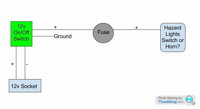
If I could wire it to the switch for the hazards, that will be much easier, as they are only a few inches away. However, if I have to go to the horn, that is also fine.
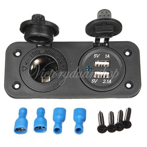
It will be one of these sockets from Ebay.
Thanks in advance for any replies
I have done a bit of googling, but haven't been able to find exactly what I want.
I want to install a 12v Socket into my series 3 Land Rover. Its mainly to charge phone and satnav. I've put 12v sockets in cars before. but they have never had an inline switch. I want an inline switch for the Land Rover.
Below is a diagram of how I think its meant to work. Can someone shed any light on if I doing this right.
If I could wire it to the switch for the hazards, that will be much easier, as they are only a few inches away. However, if I have to go to the horn, that is also fine.
It will be one of these sockets from Ebay.
Thanks in advance for any replies
OK, I'm crap at drawing so bear with me!
The first bit to the fuse is fine.
Take the + from the fuse to a switch
The ground wires don't go the the switch (unless it's an illuminated switch then it's different), attach them both to the chassis, you only need to switch the +ve wire.
From the switch to the + of the socket and ground of the socket back to the chassis.
You need to make sure that the chassis connections are to bare metal and treated when done to prevent rust.
Hope this makes sense!
Marcus
Stiggolas said:
OK, I'm crap at drawing so bear with me!
The first bit to the fuse is fine.
Take the + from the fuse to a switch
The ground wires don't go the the switch (unless it's an illuminated switch then it's different), attach them both to the chassis, you only need to switch the +ve wire.
From the switch to the + of the socket and ground of the socket back to the chassis.
You need to make sure that the chassis connections are to bare metal and treated when done to prevent rust.
Hope this makes sense!
Marcus
Thanks for the reply. The first bit to the fuse is fine.
Take the + from the fuse to a switch
The ground wires don't go the the switch (unless it's an illuminated switch then it's different), attach them both to the chassis, you only need to switch the +ve wire.
From the switch to the + of the socket and ground of the socket back to the chassis.
You need to make sure that the chassis connections are to bare metal and treated when done to prevent rust.
Hope this makes sense!
Marcus
When you say + from the fuse to a switch, do you mean the switch or do I need a second switch in the flow?
The switch I'm looking to use isn't illuminated. So, does the + get looped back to the switch at some point?
I should be able to get to a sold metal part for the ground.
The switch will only have 2 connectors (if it has more you only need to use 2 but make sure it's the right 2!)
Your diagram is basically OK but the grounds don't need to be switched so bolt to the chassis or somewhere.
The above poster said run a feed directly from the battery. Not a bad shout if you can do it, alternatively find a permanent live from the fusebox.
Your diagram is basically OK but the grounds don't need to be switched so bolt to the chassis or somewhere.
The above poster said run a feed directly from the battery. Not a bad shout if you can do it, alternatively find a permanent live from the fusebox.
Gassing Station | Home Mechanics | Top of Page | What's New | My Stuff