Diffusers non flat underneath.
Discussion


RenesisEvo said:
I may have confused or over looked something, but, AIUI:
The diffuser aims to accelerate the air out from beneath the car, creating a region of low pressure under the car; given the higher pressure on the upper surfaces of the car, the net result is a force acting downwards - downforce.
With a flat floor, you have a large expanse of perfectly smooth surface, which not only gives nice clean flow to the diffuser, but also a nice big area to reduce the pressure over - a slight pressure drop, over a large area, adds up. Without a flat underside, the air ends up tripping over all the lumps and bumps, becoming turbulent and separated, which means the dynamic pressure will be much lower, so the effect of the diffuser won't be nearly as great, as the pressure recovery starts from a worse place. You can achieve a pressure reduction under a rough underside, and this will give downforce, but without a flat floor you are limited to what you can achieve because of the losses.
Perhaps the confusion is with regards to racing cars, which are often said to be using the 'floor' to generate downforce. In my experience the 'floor' refers to the collection of panels that mount beneath the tub/powertrain, which form both the top and underside of the floor. These surfaces may incorporate a diffuser. The aim is to get as high a pressure on the top of the floor, and as low a pressure on the bottom of the floor as possible, to give the biggest difference in pressure, therefore the most downforce. The more floor area you have, the more downforce you can generate.
You are discussing ground effect (low underside pressure due to low volume of air under the car, vs the pressure above the car), and a diffuser (accelerating air into a void to generate low pressure)The diffuser aims to accelerate the air out from beneath the car, creating a region of low pressure under the car; given the higher pressure on the upper surfaces of the car, the net result is a force acting downwards - downforce.
With a flat floor, you have a large expanse of perfectly smooth surface, which not only gives nice clean flow to the diffuser, but also a nice big area to reduce the pressure over - a slight pressure drop, over a large area, adds up. Without a flat underside, the air ends up tripping over all the lumps and bumps, becoming turbulent and separated, which means the dynamic pressure will be much lower, so the effect of the diffuser won't be nearly as great, as the pressure recovery starts from a worse place. You can achieve a pressure reduction under a rough underside, and this will give downforce, but without a flat floor you are limited to what you can achieve because of the losses.
Perhaps the confusion is with regards to racing cars, which are often said to be using the 'floor' to generate downforce. In my experience the 'floor' refers to the collection of panels that mount beneath the tub/powertrain, which form both the top and underside of the floor. These surfaces may incorporate a diffuser. The aim is to get as high a pressure on the top of the floor, and as low a pressure on the bottom of the floor as possible, to give the biggest difference in pressure, therefore the most downforce. The more floor area you have, the more downforce you can generate.
AIUI as well

A flat floor preceding the diffuser isn't essential, a diffuser could start right after the front splitter without any 'floor' ahead of it...
A flat floor for ground effect isn't even essential. You can have a skirt around the car and not even have air under the car at all, to worry about flow around a lump underneath, and get HUGE downforce from 'ground effect'
The reason you see flat floors is because of aerodynamic packages as a whole. If you outline the principle of either ground effect or diffuser, then the floor properties are not an essential part of their function.
Diffuser, accelerating air into a void lowering it's pressure.
Ground effect, reducing flow of air under the car to generate a pressure differential between top and bottom of car.
!?!?
Dave
Sam_68 said:
monthefish said:
I worked for an OEM as a Design Engineer responsible for the Exterior Trim ...the simulations showed that the effect of the diffuser would have been negligable, and we were only prepared to incorporate one if it was fully functional.
Apologies for thread derailment, but do you or anyone you know have substantial experience of modelling ground effect aerodynamics? What I'm interested in, specifically, is modelling the interference/interface of a body operating in ground effect where the 'ground' surface is, in fact, water (...so the airflow being deflected by the body will in turn deflect the surface of the water to some degree).
Obviously the normal moving road wind tunnel has limitations in that the road surface is 'hard' and cannot be deflected by the airflow impinging upon it, so I'd be interested in any suggestions/experience as to how this can be more accurately modelled.
PM me if you prefer not to drift off-topic or respond on-forum.
Your query sounds interesting though.

RenesisEvo said:
Without a flat underside, the air ends up tripping over all the lumps and bumps, becoming turbulent and separated,
This is the key point (never mind all the good stuff about pressure differentials).Once it is turbulent and seperated, it is nigh-on useless in normal diffuser terms.
The point is, if you're going to design a diffuser that will work under those circumstances, it is far simpler/cheaper just to incorporate a flat floor in the first place allowing for a far simpler/cheaper diffuser.
Sam_68 said:
monthefish said:
I worked for an OEM as a Design Engineer responsible for the Exterior Trim ...the simulations showed that the effect of the diffuser would have been negligable, and we were only prepared to incorporate one if it was fully functional.
Apologies for thread derailment, but do you or anyone you know have substantial experience of modelling ground effect aerodynamics? What I'm interested in, specifically, is modelling the interference/interface of a body operating in ground effect where the 'ground' surface is, in fact, water (...so the airflow being deflected by the body will in turn deflect the surface of the water to some degree).
Obviously the normal moving road wind tunnel has limitations in that the road surface is 'hard' and cannot be deflected by the airflow impinging upon it, so I'd be interested in any suggestions/experience as to how this can be more accurately modelled.
PM me if you prefer not to drift off-topic or respond on-forum.
Some of the fundamental concepts of aerodynamics that are being battered around here would have Bernoulli turning in his grave. The underlying concepts of streamline curvature and Bernoulli's are key to the operation of a diffuser. The normal momentum equation states that a fluid flowing along a curved streamline will have an associated radial pressure gradient and by Bernoullis principle this pressure drop drives a velocity increase through the diffuser which is purely incidental. In some applications a diffusers main role is not the production of downforce but the reduction of drag, by providing a clean and optimum expansion pathway for the air from the underside of the car to expand into, keeping flow attached higher up the rear of the car and filling in a proportion of the car's wake reducing overall pressure drag.
A diffuser is just like a venturi nozzle except it is not axisymmetric, the minimum pressure is acheived at the throat (and this is the region of maximum downforce) whereas the expansion side, which you see on the rear of vehicles is purely for optimum pressure recovery to minimize the total pressure lost by the flow (ie drag).
monthefish said:
RenesisEvo said:
Without a flat underside, the air ends up tripping over all the lumps and bumps, becoming turbulent and separated,
This is the key point (never mind all the good stuff about pressure differentials).Once it is turbulent and seperated, it is nigh-on useless in normal diffuser terms.
The point is, if you're going to design a diffuser that will work under those circumstances, it is far simpler/cheaper just to incorporate a flat floor in the first place allowing for a far simpler/cheaper diffuser.
Meldonte said:
Some of the fundamental concepts of aerodynamics that are being battered around here would have Bernoulli turning in his grave. The underlying concepts of streamline curvature and Bernoulli's are key to the operation of a diffuser. The normal momentum equation states that a fluid flowing along a curved streamline will have an associated radial pressure gradient and by Bernoullis principle this pressure drop drives a velocity increase through the diffuser which is purely incidental. In some applications a diffusers main role is not the production of downforce but the reduction of drag, by providing a clean and optimum expansion pathway for the air from the underside of the car to expand into, keeping flow attached higher up the rear of the car and filling in a proportion of the car's wake reducing overall pressure drag.
A diffuser is just like a venturi nozzle except it is not axisymmetric, the minimum pressure is acheived at the throat (and this is the region of maximum downforce) whereas the expansion side, which you see on the rear of vehicles is purely for optimum pressure recovery to minimize the total pressure lost by the flow (ie drag).
Good post. My points were probably a bit iffy A diffuser is just like a venturi nozzle except it is not axisymmetric, the minimum pressure is acheived at the throat (and this is the region of maximum downforce) whereas the expansion side, which you see on the rear of vehicles is purely for optimum pressure recovery to minimize the total pressure lost by the flow (ie drag).

When you say the main role of a diffuser is in reducing drag, how is it that we can see really low drag coefficient bodies without what we conventionally see as a 'diffuser'?
I assume it's just preferential to always have some lift reduction in association with low drag for car applications anyway?
Also, when you say the throat on a diffuser, where is that point? Just before it opens up? Ie, at the point of greatest curvature of the nozzle?
Dave
tyranical said:
Same as the "vortex generators" you find on the top of some Evo's (or is it scoobs?) they do naff all too iirc.

If they did naff all I think you would struggle to find them on numerous aircraft as they would just be dead weight.
In aircraft, the vortex generated by these things re-energizes the boundary layer of slow moving air over the top of the wing and prevents flow seperation due to the adverse pressure gradient. This can lead to benefits such as improved control effectiveness at high angles of attack and increased stalling angle depending on their location on a wing.
In cars, although the role is the same, in re-energizing the boundary layer, this allows the flow to remain attached further to the rear of the car rather than seperating where the glass begins to slope down, providing wake infill , which can result in reasonable pressure drag savings at moderate-high speeds, improving your fuel economy on the motorway. Plus they look cool..
Mr Whippy said:
You are discussing ground effect (low underside pressure due to low volume of air under the car, vs the pressure above the car), and a diffuser (accelerating air into a void to generate low pressure)
It appears there are two different 'ground effects' - one seems to be the generic (perhaps misleading IMO) term for creating low pressures under a car, the other is about what happens when you bring an aerofoil in close proximity to the ground, which is entirely different but (for a racing car) can have a similar effect. Bring the front wing of an F1 car closer to the ground increases the downforce, up to the point the gap between the bottom surface and the ground is so small it chokes the flow behind it, and either the wing stalls, or (more likely) you have too little mass flow getting to the rest of the underfloor behind the front wing and you start losing overall downforce from the rear.A diffuser is used to generate the low pressure under a car as Meldonte explained better than I could, therefore it's hard to escape discussion of diffusers and what Mr Whippy has called ground effect because they are related.
I *should* know all this better because I work with F1 aerodynamics, but the reality is I don't spend much time worrying about the aerodynamic theory behind it all, I just test the designs given to me

Mr Whippy said:
Also, when you say the throat on a diffuser, where is that point? Just before it opens up? Ie, at the point of greatest curvature of the nozzle?
At the start of the diffuser - for an F1 car there's a clearly defined point at which the diffuser ramps up from the underfloor (defined by the rules), it is at this point you typically see the lowest pressure, but the low pressure region extends quite some way ahead of this.Edited by RenesisEvo on Wednesday 3rd August 11:45
Edited by RenesisEvo on Wednesday 3rd August 11:46
Mr Whippy said:
Good post. My points were probably a bit iffy
When you say the main role of a diffuser is in reducing drag, how is it that we can see really low drag coefficient bodies without what we conventionally see as a 'diffuser'?
I assume it's just preferential to always have some lift reduction in association with low drag for car applications anyway?
Also, when you say the throat on a diffuser, where is that point? Just before it opens up? Ie, at the point of greatest curvature of the nozzle?
Dave
I wouldn't say that the main role of a diffuser is to reduce drag as there are more effective ways but a decent design will provide a drag reduction along side an increase in downforce.
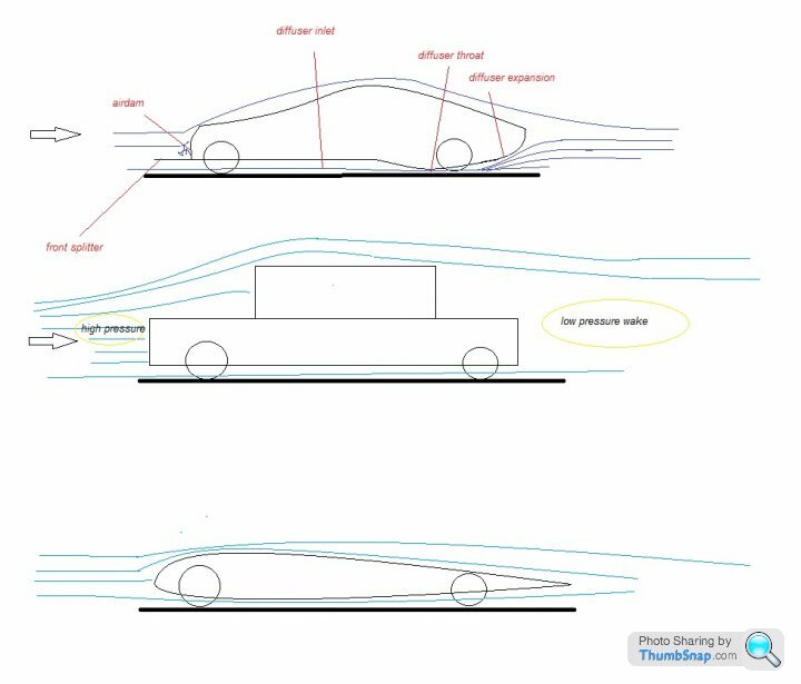
The piece of artistic genius above hopefully helps to illustrate some of the concepts. On every body in a immersed flow no matter how efficient there is a stagnation point where the flow is brought to rest in a particular location at or near the front of the body. Bernoullis equation basically says that the static pressure + dynamic pressure + potential pressure of an incompressible flow (air is deemed incompressible below mach numbers of less than 0.3) remains constant along a streamline and because the density of air is pretty small we can ignore the potential pressure difference for small changes in vertical height from the start to the finish of the streamline. So what we end up with is if we decrease the static pressure of the air, its dynamic pressure (speed) must increase for Bernoullis to hold.
Bearing this in the mind, on the top car in the picture. The air is brought effectively to rest at the airdam, it looses its dynamic pressure so its static pressure must increase. Under the car there is no such airdam so the pressure remains the same and there is a resultant downforce on the front splitter.
Further along as the diffuser inlet approaches the ground, the air is not "squeezed" contrary to popular belief as this would increase its pressure, it is better to think of it as being "stretched out" in the longituduinal direction and conservation of massflow or the continuity equation can show this to be true. The radius of curvature of the streamlines is maximum at the throat of the diffuser (mimimum cross sectional area of the flow) and so the pressure reduction relative to ambient is maximum and the air looses static pressure and must increase its dynamic pressure accordingly, it accelerates and is "stretched out". it is the reduction of pressure under the car relative to the ambient pressure above the car which provides the downforce.
Further downstream in the diffuser expansion we have already extracted the necessary downforce from the air so it could be left at that, but that would leave us with a jet of fast moving air at the rear of the car at ground level and a large wake higher up the rear end. It is better to use this air and expand it into this wake, increasing its pressure. This is known as pressure recovery as the air in the diffuser slows down, expands and thus recovers STATIC pressure. Ignoring friction effects the total pressure is no different at any point through the flow from where it starts to where it ends.
If we fill in the wake at the rear and increase its static pressure, then there is less of a front-aft pressure differential between the region of high pressure at the air dam and the region of relatively lower pressure in the wake. This pressure diffential is known as form or pressure drag.
In the second picture you can see a relatively unaerodynamic model of a bluff boxy car (Nissan cube owners listen up - the clue is in the name!) It is obvious to see the huge form drag that will result due to the large stagnation zone at the front of the car producing high static pressure and the massive wake at the rear producing almost a vacuum or low static pressure. Because of the large pressure differential and large areas over which this pressure acts on the car body it will have huge pressure drag and is quite literally as aerodynamic as a brick. The air cannot follow the sharp contours of the body (because the radius of curvature is far too small) and seperates immediately, generating turbulence and a huge wake.
The third picture is an example of an ideal aerodynamic car body without a diffuser. If the ride height was sufficiently high to ignore ground effects then the symmetric body would produce no lift/downforce as the streamline curvature and thus pressure changes of the air are identical above and below the body and no net force would act. The reason the drag is minimized is the flow remains attached all the way to the rear of the car and each side re joins at the trailing edge and thus wake at the rear is theoretically non existant. There is still a small stagnation point at the front of the car there the dynamic pressure is converted to static pressure above ambient and this will result in a small amount of pressure drag.
Lift on a car body will I guess reduce non-aero drag such as tyre rolling resistance etc but I suspect the effects are minimal in comparison to the weight of the car unless it is a very specialist machine.
tyranical said:
rhinochopig said:
Not actually true. They have been proven in the wind-tunnel. Mitsubishi engineers actually published a paper on the subject.
Yeh I read the Corsa VXR has been proven in the wind tunnel too with all its slits and diffusers.They're hardly going to say "we fitted them to your car but its utter b
 ks and they do fk all" are they?
Cars like the Escort Cosworth, and the Mitsubaru cars have their ostentatious appendages for a reason .... maybe not a reason that is relevent at the local drivethru, or on the daily commute, but genuine a genuine performance advantage none the less.
Meldonte said:
I wouldn't say that the main role of a diffuser is to reduce drag as there are more effective ways but a decent design will provide a drag reduction along side an increase in downforce.
The piece of artistic genius above hopefully helps to illustrate some of the concepts. On every body in a immersed flow no matter how efficient there is a stagnation point where the flow is brought to rest in a particular location at or near the front of the body. Bernoullis equation basically says that the static pressure + dynamic pressure + potential pressure of an incompressible flow (air is deemed incompressible below mach numbers of less than 0.3) remains constant along a streamline and because the density of air is pretty small we can ignore the potential pressure difference for small changes in vertical height from the start to the finish of the streamline. So what we end up with is if we decrease the static pressure of the air, its dynamic pressure (speed) must increase for Bernoullis to hold.
Bearing this in the mind, on the top car in the picture. The air is brought effectively to rest at the airdam, it looses its dynamic pressure so its static pressure must increase. Under the car there is no such airdam so the pressure remains the same and there is a resultant downforce on the front splitter.
Further along as the diffuser inlet approaches the ground, the air is not "squeezed" contrary to popular belief as this would increase its pressure, it is better to think of it as being "stretched out" in the longituduinal direction and conservation of massflow or the continuity equation can show this to be true. The radius of curvature of the streamlines is maximum at the throat of the diffuser (mimimum cross sectional area of the flow) and so the pressure reduction relative to ambient is maximum and the air looses static pressure and must increase its dynamic pressure accordingly, it accelerates and is "stretched out". it is the reduction of pressure under the car relative to the ambient pressure above the car which provides the downforce.
Further downstream in the diffuser expansion we have already extracted the necessary downforce from the air so it could be left at that, but that would leave us with a jet of fast moving air at the rear of the car at ground level and a large wake higher up the rear end. It is better to use this air and expand it into this wake, increasing its pressure. This is known as pressure recovery as the air in the diffuser slows down, expands and thus recovers STATIC pressure. Ignoring friction effects the total pressure is no different at any point through the flow from where it starts to where it ends.
If we fill in the wake at the rear and increase its static pressure, then there is less of a front-aft pressure differential between the region of high pressure at the air dam and the region of relatively lower pressure in the wake. This pressure diffential is known as form or pressure drag.
In the second picture you can see a relatively unaerodynamic model of a bluff boxy car (Nissan cube owners listen up - the clue is in the name!) It is obvious to see the huge form drag that will result due to the large stagnation zone at the front of the car producing high static pressure and the massive wake at the rear producing almost a vacuum or low static pressure. Because of the large pressure differential and large areas over which this pressure acts on the car body it will have huge pressure drag and is quite literally as aerodynamic as a brick. The air cannot follow the sharp contours of the body (because the radius of curvature is far too small) and seperates immediately, generating turbulence and a huge wake.
The third picture is an example of an ideal aerodynamic car body without a diffuser. If the ride height was sufficiently high to ignore ground effects then the symmetric body would produce no lift/downforce as the streamline curvature and thus pressure changes of the air are identical above and below the body and no net force would act. The reason the drag is minimized is the flow remains attached all the way to the rear of the car and each side re joins at the trailing edge and thus wake at the rear is theoretically non existant. There is still a small stagnation point at the front of the car there the dynamic pressure is converted to static pressure above ambient and this will result in a small amount of pressure drag.
Lift on a car body will I guess reduce non-aero drag such as tyre rolling resistance etc but I suspect the effects are minimal in comparison to the weight of the car unless it is a very specialist machine.
Can you also explain why with my Mk3 Clio RS (Which has a rear diffuser, but no flat floor) I seem to get bug-splats on the REAR bumper?? ...and no, i'm not reversing everywhere at 80mph!
TheRoadWarrior said:
Thats an excellent post, thanks for the info.
Can you also explain why with my Mk3 Clio RS (Which has a rear diffuser, but no flat floor) I seem to get bug-splats on the REAR bumper?? ...and no, i'm not reversing everywhere at 80mph!
Because french cars are sCan you also explain why with my Mk3 Clio RS (Which has a rear diffuser, but no flat floor) I seem to get bug-splats on the REAR bumper?? ...and no, i'm not reversing everywhere at 80mph!
t and slow, so the bugs are out performing you, and crashing into your rear bumper.Meldonte said:
Firstly to respond to sam, to carry out that kind of modelling would be immensley complex and CPU/memory intensive, you are looking at using multiphysics / FSI ( Fluid structure interaction techniques) which if you have not heard of, is a sort of horrible blend of CFD and FEA codes which can work on an iterative basis.... ie. initial geometry and boundary conditions produces x aerodynamic force. x aerodynamic force deforms initial geometry by y and changes boundary conditions by z. then y and z are fed back into the model to generate a new x until the system converges. Really clever stuff but hideously complicated to get it to work effectively and a much less developed area of computer modelling than conventional FE or CFD methods. Unless your project is to specifically model that situation I would recommend an assumption that for low dynamic pressures deformations of the ground (water) are negligible and thus the ground can be treated as a solid body.
Thanks for that - very helpful!The project would need to specifically model that situation, since it will need to deal with a transition between low speed (displacement) and the high speed regime where, as you say, the 'ground' (water) can effectively be treated as a solid surface.
You seem to be confirming what I suspected, though: that there's no off-the-shelf, well established and reliable CFD package that could cope with the scenario?
Sounds like, given project budget and objectives, we'll be better off sticking to good, old-fashioned model testing...

TheRoadWarrior said:
Thats an excellent post, thanks for the info.
Can you also explain why with my Mk3 Clio RS (Which has a rear diffuser, but no flat floor) I seem to get bug-splats on the REAR bumper?? ...and no, i'm not reversing everywhere at 80mph!
My best guess would be turbulence. Because your car does not have a flat floor then all the bluff shapes under the car will cause a highly turbulent flow consisting of a layered structure of eddies and vortices across ever reducing length scales. When these eddies are still large and powerful and then further contorted by the effects of the rear diffuser changing their shape, although the mean flow would still be as pictured above, if you were to take a snapshot in time of what the flow looked like you would see the effect these eddies had on the streamlines causing them to take very strange paths, with some of your flies which sound like a handy flow visualisation technique being propelled literally into the bumper like pictured below. It is worth remembering the rear of a car is a really low pressure zone and that is why dust/grime gets sucked onto the back of a car and it gets dirty first, same principles for bugs I guess but a random fluctuation of turbulence can give the instantaneous shove needed for them to go squish. Either that or the recent good weather has caused a massive rise in population of the notoriously anti euro Mitsubishi Zero beetle.Can you also explain why with my Mk3 Clio RS (Which has a rear diffuser, but no flat floor) I seem to get bug-splats on the REAR bumper?? ...and no, i'm not reversing everywhere at 80mph!

Meldonte said:
TheRoadWarrior said:
Thats an excellent post, thanks for the info.
Can you also explain why with my Mk3 Clio RS (Which has a rear diffuser, but no flat floor) I seem to get bug-splats on the REAR bumper?? ...and no, i'm not reversing everywhere at 80mph!
My best guess would be turbulence. Because your car does not have a flat floor then all the bluff shapes under the car will cause a highly turbulent flow consisting of a layered structure of eddies and vortices across ever reducing length scales. When these eddies are still large and powerful and then further contorted by the effects of the rear diffuser changing their shape, although the mean flow would still be as pictured above, if you were to take a snapshot in time of what the flow looked like you would see the effect these eddies had on the streamlines causing them to take very strange paths, with some of your flies which sound like a handy flow visualisation technique being propelled literally into the bumper like pictured below. It is worth remembering the rear of a car is a really low pressure zone and that is why dust/grime gets sucked onto the back of a car and it gets dirty first, same principles for bugs I guess but a random fluctuation of turbulence can give the instantaneous shove needed for them to go squish. Either that or the recent good weather has caused a massive rise in population of the notoriously anti euro Mitsubishi Zero beetle.Can you also explain why with my Mk3 Clio RS (Which has a rear diffuser, but no flat floor) I seem to get bug-splats on the REAR bumper?? ...and no, i'm not reversing everywhere at 80mph!

Traveller said:
Meldonte said:
interesting stuff.. JR said:
That is the basic problem! Cars are generally like wings and lift over 100mph can be a big problem, esp over 150mph hence the use of ground effect, wings spoilers etc to counter act the basic wing profile.
Yup, got that, but meldon mentions the following,Meldonte said:
The third picture is an example of an ideal aerodynamic car body without a diffuser. If the ride height was sufficiently high to ignore ground effects then the symmetric body would produce no lift/downforce as the streamline curvature and thus pressure changes of the air are identical above and below the body and no net force would act.
If the above is the case, then the same should be true for an aircraft aerofoil section, which seem to have a very similar upper and lower camber to chord relationship.Traveller said:
Meldonte said:
The third picture is an example of an ideal aerodynamic car body without a diffuser. If the ride height was sufficiently high to ignore ground effects then the symmetric body would produce no lift/downforce as the streamline curvature and thus pressure changes of the air are identical above and below the body and no net force would act.
If the above is the case, then the same should be true for an aircraft aerofoil section, which seem to have a very similar upper and lower camber to chord relationship. JR said:
In Meldonte's quote pay particular attention to 'symmetric' - he is talking about a theoretical case where the upper profile is the mirror image of the lower profile, which is not the case for a wing.
that makes sense, was thrown off by the diagram, and somehow, in my "Friday - almost weekend daze", understood that to relate to front and back symmetry rather than top and bottom. A good discussion. Gassing Station | General Gassing | Top of Page | What's New | My Stuff