Question for the mechanical engineers amongst us.
Discussion


I have had some brackets machined which hold on the brake calipers. The bracket can be seen inside the disc in this photo.
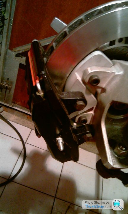
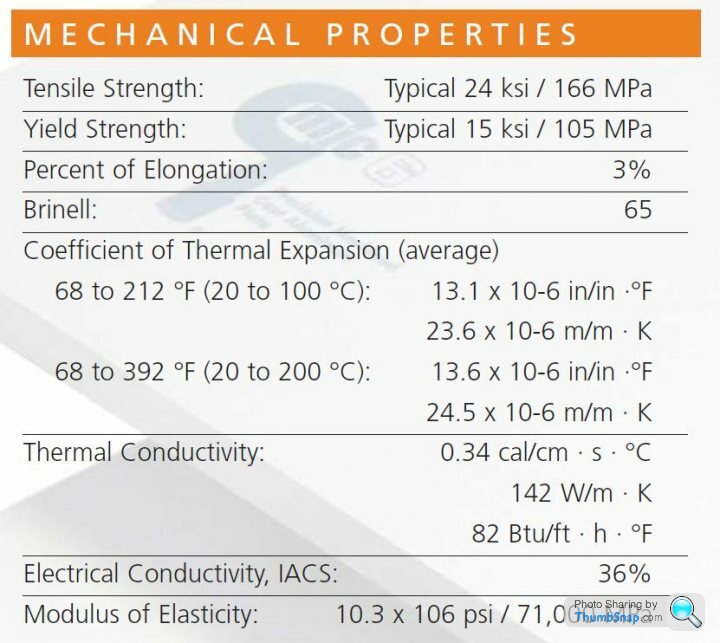
I have been told by the guy who made them that now he knows the use case he is not sure the material the brackets are made from has the correct properties. They are made frpom MIC 6 for which is a cast tooling alloy. The properties are as follows:
 |http://thumbsnap.com/oSnHCp5i[/url]
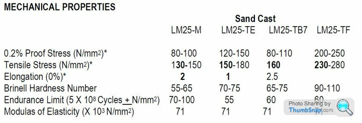
The bracket bolts to two lugs on the upright (each lug has a csa of around 300mm² - small compared to the csa which would have to shear on the bracket, which is about 100mm² csa at its narrowest point). The upright is sand cast from LM25. ML25 Spec is below:
Sure neither of these alloys have the tensile strength of 6061, but given the lugs to which the bracket is bolted has material properties similar to the MIC 6 (from what I can work out)is there likely to be an issue here?
I have been told by the guy who made them that now he knows the use case he is not sure the material the brackets are made from has the correct properties. They are made frpom MIC 6 for which is a cast tooling alloy. The properties are as follows:
|http://thumbsnap.com/oSnHCp5i[/url]The bracket bolts to two lugs on the upright (each lug has a csa of around 300mm² - small compared to the csa which would have to shear on the bracket, which is about 100mm² csa at its narrowest point). The upright is sand cast from LM25. ML25 Spec is below:
Sure neither of these alloys have the tensile strength of 6061, but given the lugs to which the bracket is bolted has material properties similar to the MIC 6 (from what I can work out)is there likely to be an issue here?
I haven't read the post and I wouldn't understand it anyway as I never liked material science.
What I'd be worried about is that if you got a little play in the wheel bearings, what with the bracket being so close to the disc, something would touch. Can't you get a bit more of a gap.
Thats the only thing I can add.
What I'd be worried about is that if you got a little play in the wheel bearings, what with the bracket being so close to the disc, something would touch. Can't you get a bit more of a gap.
Thats the only thing I can add.
I can't talk material properties but my 'engineers eye' says that will be plenty strong enough in pretty much any grade.
Compared to the lugs on the upright your bracket has way more meat to it.
Running bigger discs and calipers will be transferring greater loads to the lugs on the upright. IMHO they would likely fail before your bracket.
Steve
Compared to the lugs on the upright your bracket has way more meat to it.
Running bigger discs and calipers will be transferring greater loads to the lugs on the upright. IMHO they would likely fail before your bracket.
Steve
Mr Pidgeon, There is around 2mm of clearance on the bracket, which is more than the caliper has on the wheel! I'ts not a high usage car so everything will beb checked every 1000 miles or so max. Confident it will take 30 years to knacker a wheel bearing!
Steve - your thoughts and mine are the same. FWIW N/mm² and Mpa are the same, so I am reassured the difference in shear strength is minimal.
That said a 1 foot free length of 120mm csa MIC 6 held in a big vice and smacked with a 7lb hammer did shear after a few (very)heavy blows.
Steve - your thoughts and mine are the same. FWIW N/mm² and Mpa are the same, so I am reassured the difference in shear strength is minimal.
That said a 1 foot free length of 120mm csa MIC 6 held in a big vice and smacked with a 7lb hammer did shear after a few (very)heavy blows.
In that case I'm pretty sure you have your disc/rotor on the wrong way around, and that one should be on the other side of the car.
The vanes for cooling act like a turbine, drawing cool air from the centre and throwing it out of the perimeter. They need to be trailing in order to do this though...... if that makes sense
The vanes for cooling act like a turbine, drawing cool air from the centre and throwing it out of the perimeter. They need to be trailing in order to do this though...... if that makes sense
Dave Brookes said:
I don't know the full physics/fluid dynamics regarding rotation speed versus air flow. But turbos and turbines throw air out from the centre a lot better than sucking it in from the outside.
Just seems odd to me.
Is anyone on here able to confirm or deny for me? Genuine question.
I'm not an expert on brake discs, but I reckon IBDAET has it right. I do work with turbomachinery and you're absolutely right about centrifugal compressors working best from inside to outside, but if there is a duct to bring air from outside the car to the wheel, it does seem logical that the disc cooling would be from OD to ID. There are devices that work on this principle too.Just seems odd to me.
Is anyone on here able to confirm or deny for me? Genuine question.
Instructions for fitting brake discs always say the internal air passages must curve inside to outer edge backwards to the direction of rotation. When spun in the normal direction, air spills from the centre out through the passages, like a Catherine wheel. Feeding cooling air against this flow will have reduced effect.
Cooling ducts aimed at the outer part of the disc are made to feed air to the flat faces in contact with the pads and not into the internal passages. They should also feed air in equal amounts to both sides to avoid differential cooling/contraction..
Best disc cooling is by combining air feeds to the centre and to the flat faces.
JohnMcL said:
Instructions for fitting brake discs always say the internal air passages must curve inside to outer edge backwards to the direction of rotation. When spun in the normal direction, air spills from the centre out through the passages, like a Catherine wheel. Feeding cooling air against this flow will have reduced effect.
Cooling ducts aimed at the outer part of the disc are made to feed air to the flat faces in contact with the pads and not into the internal passages. They should also feed air in equal amounts to both sides to avoid differential cooling/contraction..
Best disc cooling is by combining air feeds to the centre and to the flat faces.
I stand corrected. Thank you.Cooling ducts aimed at the outer part of the disc are made to feed air to the flat faces in contact with the pads and not into the internal passages. They should also feed air in equal amounts to both sides to avoid differential cooling/contraction..
Best disc cooling is by combining air feeds to the centre and to the flat faces.
In this design, it is not the absolute tensile strength that is important, because the sections are easily large enough to take the loadings without being pushed into plastic deformation.
However, it could be a fatigue cycle issue, as brake mounts can be subjected to "chatter" and "vibration"
In this design, the lack of load spreading washers is poor, and we can't see what the fasteners are threaded into (plain threads, helicoils etc). In all cases, crack propagation from a "sharp" edge is to be avoided!
Also, as the adaptor bracket is pretty much "trapped" in it's location, even a fairly major failure will probably not result in brake failure (more like to result in a jammed / locked on brake actually, which can be worse!)
Most likely failure will be the fasteners coming undone, so lockwire might be used, followed by localised cracking, so inspect regularly!
What's the lower ball joint as well?
Looks similar to what most people use as a top joint?
It's hard to see clearly, but that worries me more than the brake.
https://www.formulastudent.de/academy/pats-corner/...
Looks similar to what most people use as a top joint?
It's hard to see clearly, but that worries me more than the brake.
https://www.formulastudent.de/academy/pats-corner/...
Max_Torque said:
In this design, it is not the absolute tensile strength that is important, because the sections are easily large enough to take the loadings without being pushed into plastic deformation.
However, it could be a fatigue cycle issue, as brake mounts can be subjected to "chatter" and "vibration"
In this design, the lack of load spreading washers is poor, and we can't see what the fasteners are threaded into (plain threads, helicoils etc). In all cases, crack propagation from a "sharp" edge is to be avoided!
Also, as the adaptor bracket is pretty much "trapped" in it's location, even a fairly major failure will probably not result in brake failure (more like to result in a jammed / locked on brake actually, which can be worse!)
Most likely failure will be the fasteners coming undone, so lockwire might be used, followed by localised cracking, so inspect regularly!
As Max_Torque has hinted at I would be most worried about the fasteners in this case. Cast plate generally won't hold threads especially well so at minimum I would want to use an insert such as a Helicoil. Washers would also be advisable - you could use something like a Nordlock pair (Must be used as a pair!) to provide a locking function.However, it could be a fatigue cycle issue, as brake mounts can be subjected to "chatter" and "vibration"
In this design, the lack of load spreading washers is poor, and we can't see what the fasteners are threaded into (plain threads, helicoils etc). In all cases, crack propagation from a "sharp" edge is to be avoided!
Also, as the adaptor bracket is pretty much "trapped" in it's location, even a fairly major failure will probably not result in brake failure (more like to result in a jammed / locked on brake actually, which can be worse!)
Most likely failure will be the fasteners coming undone, so lockwire might be used, followed by localised cracking, so inspect regularly!
Gassing Station | Kit Cars | Top of Page | What's New | My Stuff