Tube Chassis "VW Caddy" Project
Discussion


Are you using bolt in wheel bearing hub unit's ?? there are lots out there now and they make the uprights way easier to make as your tolerances don't have to be as tight. Heat expansion of an upright means the bearing expands less than say billet 6061 so the bearings have to be a interference fit in the old school way of doing things, and they seem very stiff when cold due to that. My Old Ultima GTR units where very tight to start with, and that was cast Ally that's not as dense as billet so does not expand as much. I use Corvette Hubs but I bet there are smaller more compact VW units that would be better suited.
GTRCLIVE said:
Another guy as nuts as me.... But it is fun doing everything yourself, Caddy V6 DTM stile I like you thinking..... Will be watching this thread.
Thank God for the two of you (and others such as Andy)!PH has been on the decline for years but it's threads like yours that keep me on here!
Clive's 962 will always have the top step in my heart but I think this project is my second favourite on here, having had a scratch built RC pick up truck with an on-road chassis and crzy engine hiding underneath! Rocket ship!
Clive, first of all I have read through your build so many times, I'm honoured! 
Also many thanks dom9 for the kind words, I have big expectations to live up to!
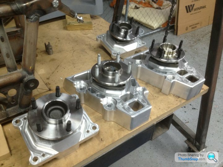
I'll be using bolt-on hubs for the rear definitely, as I need the driveshaft splines, will be using standard Audi A6 hubs and driveshafts (I think the track is quite close)
I'm doing my best to keep weight down, so hadn't considered the bolt-ons much as the ones I have are pretty heavy
However not really considered heat expansion much, do you know what kind of temperatures they would be subject to?
Had thought that aluminium brake bells and possibly even aluminium hubs would have helped dissipate heat from the rotor
Have been looking at all sorts of bearing configurations, most recently using large diameter taper bearings, but sealing them is a pain.
current design


As for the chassis, have a better camera now, and managed to move it to take some better photos

now had the rear 'up' diagonals made and welded in

Also many thanks dom9 for the kind words, I have big expectations to live up to!
I'll be using bolt-on hubs for the rear definitely, as I need the driveshaft splines, will be using standard Audi A6 hubs and driveshafts (I think the track is quite close)
I'm doing my best to keep weight down, so hadn't considered the bolt-ons much as the ones I have are pretty heavy
However not really considered heat expansion much, do you know what kind of temperatures they would be subject to?
Had thought that aluminium brake bells and possibly even aluminium hubs would have helped dissipate heat from the rotor
Have been looking at all sorts of bearing configurations, most recently using large diameter taper bearings, but sealing them is a pain.
current design
As for the chassis, have a better camera now, and managed to move it to take some better photos
now had the rear 'up' diagonals made and welded in
Fantastic project.
I design and build race cars for a living and very impressed with your work. Nice to see you cracking on so fast with the car.
I have done lots of upright and hub designs for race cars so these are my thoughts for what it's worth.
Running bearings in a aluminium upright without a steel sleeve is a massive pain in the ass. The expansion of the Aluminium is the problem it's quite a bit more than Steel as you know. So you would need to run the bearings tight when cold which is not idea. You are going to really suffer with bearing life and you will constantly be adjusting the bearings.
If I was you I would be going for a bolt in hub/bearing assembly. They will be fit and forget items and very easy to integrate into your design.
If you really want to do something light weight then you really need to have a steel sleeve that is fitted into the Aluminium upright first. I would go for minimum sleeve wall thickness of around 3mm. Then you can press the bearing and hub assembly into the steel sleeve.
Also a little suggestion on your upright design. Have the fillet webs run to the caliper mounting boss area it will stiffen up the caliper mountings and help stop any flex in that area. You may need to add an extra web if you do this but you can make them all a little thinner to offset the weight added.
Great work looking forward to seeing more.
Thank you, means a lot coming from someone who does this professionally!
For me it's only a hobby at the moment I guess, but probably something i'd like to be doing in the future
Progress hasn't been that quick but the design stage has and still is taking a lot of time and effort!
Bit unfortunate about hearings in ally being a no-no, but on the advice of yourself and Clive I've done some more work on my upright design


Steering arm is a bit temporary, drew it up in work
bumped the webs up to 10 to bring them close to the caliper mounts as suggested.
the caliper there isn't final at all, just what I could get a model of from GrabCad!
So the dimensions may change, depends which brakes I can afford.
Weight wise I'm quite happy with the body of it but the hub itself bearing and housing are heavy, have one in the kitchen.
So I may well go with turning my own hubs and bearing carriers, becuase i was pretty short of work on this project anyway

Edit, 3D view and downloadable from https://grabcad.com/library/front-upright-aluminiu...
Model for exploded and regular assembly for anyone interested
For me it's only a hobby at the moment I guess, but probably something i'd like to be doing in the future
Progress hasn't been that quick but the design stage has and still is taking a lot of time and effort!
Bit unfortunate about hearings in ally being a no-no, but on the advice of yourself and Clive I've done some more work on my upright design
Steering arm is a bit temporary, drew it up in work
bumped the webs up to 10 to bring them close to the caliper mounts as suggested.
the caliper there isn't final at all, just what I could get a model of from GrabCad!
So the dimensions may change, depends which brakes I can afford.
Weight wise I'm quite happy with the body of it but the hub itself bearing and housing are heavy, have one in the kitchen.
So I may well go with turning my own hubs and bearing carriers, becuase i was pretty short of work on this project anyway
Edit, 3D view and downloadable from https://grabcad.com/library/front-upright-aluminiu...
Model for exploded and regular assembly for anyone interested
Edited by 43655 on Tuesday 2nd December 22:43
bnracing said:
Fantastic project.
I design and build race cars for a living and very impressed with your work. Nice to see you cracking on so fast with the car.
I have done lots of upright and hub designs for race cars so these are my thoughts for what it's worth.
Running bearings in a aluminium upright without a steel sleeve is a massive pain in the ass. The expansion of the Aluminium is the problem it's quite a bit more than Steel as you know. So you would need to run the bearings tight when cold which is not idea. You are going to really suffer with bearing life and you will constantly be adjusting the bearings.
If I was you I would be going for a bolt in hub/bearing assembly. They will be fit and forget items and very easy to integrate into your design.
If you really want to do something light weight then you really need to have a steel sleeve that is fitted into the Aluminium upright first. I would go for minimum sleeve wall thickness of around 3mm. Then you can press the bearing and hub assembly into the steel sleeve.
Also a little suggestion on your upright design. Have the fillet webs run to the caliper mounting boss area it will stiffen up the caliper mountings and help stop any flex in that area. You may need to add an extra web if you do this but you can make them all a little thinner to offset the weight added.
Great work looking forward to seeing more.
Interesting stuff, I have never sat down and thought about it before, but that probably explains why S1 Elise wheel bearing life is so crap.I design and build race cars for a living and very impressed with your work. Nice to see you cracking on so fast with the car.
I have done lots of upright and hub designs for race cars so these are my thoughts for what it's worth.
Running bearings in a aluminium upright without a steel sleeve is a massive pain in the ass. The expansion of the Aluminium is the problem it's quite a bit more than Steel as you know. So you would need to run the bearings tight when cold which is not idea. You are going to really suffer with bearing life and you will constantly be adjusting the bearings.
If I was you I would be going for a bolt in hub/bearing assembly. They will be fit and forget items and very easy to integrate into your design.
If you really want to do something light weight then you really need to have a steel sleeve that is fitted into the Aluminium upright first. I would go for minimum sleeve wall thickness of around 3mm. Then you can press the bearing and hub assembly into the steel sleeve.
Also a little suggestion on your upright design. Have the fillet webs run to the caliper mounting boss area it will stiffen up the caliper mountings and help stop any flex in that area. You may need to add an extra web if you do this but you can make them all a little thinner to offset the weight added.
Great work looking forward to seeing more.
43655 said:
Hello all;
Welcome to my project!
It started off as tidying up my '88 VW Caddy, but I got fascinated by motorsport design and engineering at the same kind of time, wanting to ditch the ancient-tech leaf springs for 4-link axle etc, then toyed with a mid engine setup, bought a gearbox and subframe etc from an Audi 80 to suit.
Fast forward a few months, the caddy is now only going to be used as a buck for taking GRP moulds off.
Much to the dismay of the VW Caddy Forum
It will have Audi Quattro-style arches and 'side skirts' to bump it out to 1850mm wide (to match the Ultima GTR)
Mid engine 2.7T V6 mounted to an 01E DQS 6 speed gearbox
I have designed a full tube chassis for the car, as well as plotting front and rear suspension geometry, uprights etc
At the time of writing I'd say the CAD designing side is about 90% there and the chassis fabrication has started
So, photos:


(model is pretty crap, I can't do surface modelling)
This is my first attempt at bot designing and making something of this magnitude.
I welcome criticism and suggestions, as I know there are many much more knowledgeable people on this forum!
Hi Henk, you have a very nice project and I will be following your build with interest.Welcome to my project!
It started off as tidying up my '88 VW Caddy, but I got fascinated by motorsport design and engineering at the same kind of time, wanting to ditch the ancient-tech leaf springs for 4-link axle etc, then toyed with a mid engine setup, bought a gearbox and subframe etc from an Audi 80 to suit.
Fast forward a few months, the caddy is now only going to be used as a buck for taking GRP moulds off.
Much to the dismay of the VW Caddy Forum
It will have Audi Quattro-style arches and 'side skirts' to bump it out to 1850mm wide (to match the Ultima GTR)
Mid engine 2.7T V6 mounted to an 01E DQS 6 speed gearbox
I have designed a full tube chassis for the car, as well as plotting front and rear suspension geometry, uprights etc
At the time of writing I'd say the CAD designing side is about 90% there and the chassis fabrication has started
So, photos:
(model is pretty crap, I can't do surface modelling)
This is my first attempt at bot designing and making something of this magnitude.
I welcome criticism and suggestions, as I know there are many much more knowledgeable people on this forum!
Keep up the good work.
Cheers
Italo
This is excellent - please can you tell me which software you used for the tube chassis design, and also are you using MIG or TIG for the tubes. I have become reasonably proficient at MIG and am considering making something, but I fear that TIG is probably the way to go, in which case I have some practice to do first. Thanks very much.
Italo, Thank you 
All the design work is done in Solidworks 2014, the Weldments feature makes designing tube structures really easy!
Version 1 of the chassis took me about 4 hours to knock up
It's all MIG welded I have a second hand Cebora Autostar 190, a decent TIG at ~£1500 is a bit out of my budget!
I'll be TIG welding the wishbones though, as I can do them in work
Each has it's pros and cons really
Edited by 43655 on Saturday 6th December 12:22
Forgive my ignorance here, but after the problems that bnracing mentioned why manufacture your own uprights and wishbones (unless you want to scraatch build everything of course)?
Wouldn't it be better to take an existing set up like the VX220 / Elise series 2 where you have access to numerous second hand parts, known geometry values, all things like the calipers, discs, bushes, shims and ball joints readily available.
It seems like you making work for yourself. Especially after the link to the wide bodied Golf stated that it was awful to drive
Ebo100 said:
Forgive my ignorance here, but after the problems that bnracing mentioned why manufacture your own uprights and wishbones (unless you want to scraatch build everything of course)?
Wouldn't it be better to take an existing set up like the VX220 / Elise series 2 where you have access to numerous second hand parts, known geometry values, all things like the calipers, discs, bushes, shims and ball joints readily available.
It seems like you making work for yourself. Especially after the link to the wide bodied Golf stated that it was awful to drive
I wouldn't consider them problems, I have taken his and Clive's advice and modified to suit and now have a better part. Wouldn't it be better to take an existing set up like the VX220 / Elise series 2 where you have access to numerous second hand parts, known geometry values, all things like the calipers, discs, bushes, shims and ball joints readily available.
It seems like you making work for yourself. Especially after the link to the wide bodied Golf stated that it was awful to drive
Anyway the suspension geometry has been plotted out, I have a much wider ball joint separation than most stock uprights and there isn't that much that's suitable.
The beauty is that by designing upright geometry wishbones and chassis together is that I'm not having to work with any particularly compromising element in theory.
That said at least you didn't suggest using standard kit car part. Rod ends in bending is all i need to say, and they bloody love them too

Could I have used parts and geometry off another car sure, I know of a few similar projects done that way (Lasupra and ETS Hilux spring to mind)
Not to be assuming I know better than Lotus engineers but what's to say that they're really that good?
In fact why bother building a car when you could just buy one?
Maybe I should have just taken out a huge loan and bought an Ultima or something?
(I'm 22, and building this with ~£16k per year income)
Nah, I'm a designer, and wannabe-fabricator, so for me this is a design project, an engineering project, and generally an hell of a learning experience.
I'd love to get to do something like this professionally one day, so this is my way of educating myself I guess.
With regards to the golf, I'm not surprised it sucked, it's short, very light rear, RWD car, with a huge V8 dumped in the front.
Sure it's a VW-scene wet dream, but this is completely different, don't you think? Apples-and-oranges
The only think VW about it will be a very vague resemblance, what with the widening, shortening and general chopping up.
Sure it's a rubbish body to use really, but it was MY car.
It will be more Ultima or GT40 than it will ever be VW though!
Anyway I certainly hope i can make a car that handles well, mid engine is common and proven, chassis should be pretty stiff and safe, and I've spent most of my free time in the last few years researching, reading others' builds, saving photos etc
Edited by 43655 on Monday 8th December 21:20

43655 said:
Thank you, means a lot coming from someone who does this professionally!
For me it's only a hobby at the moment I guess, but probably something i'd like to be doing in the future
Progress hasn't been that quick but the design stage has and still is taking a lot of time and effort!
Bit unfortunate about hearings in ally being a no-no, but on the advice of yourself and Clive I've done some more work on my upright design
Steering arm is a bit temporary, drew it up in work
bumped the webs up to 10 to bring them close to the caliper mounts as suggested.
the caliper there isn't final at all, just what I could get a model of from GrabCad!
So the dimensions may change, depends which brakes I can afford.
Weight wise I'm quite happy with the body of it but the hub itself bearing and housing are heavy, have one in the kitchen.
So I may well go with turning my own hubs and bearing carriers, becuase i was pretty short of work on this project anyway
Edit, 3D view and downloadable from https://grabcad.com/library/front-upright-aluminiu...
Model for exploded and regular assembly for anyone interested
Good work the upright looks great now.For me it's only a hobby at the moment I guess, but probably something i'd like to be doing in the future
Progress hasn't been that quick but the design stage has and still is taking a lot of time and effort!
Bit unfortunate about hearings in ally being a no-no, but on the advice of yourself and Clive I've done some more work on my upright design
Steering arm is a bit temporary, drew it up in work
bumped the webs up to 10 to bring them close to the caliper mounts as suggested.
the caliper there isn't final at all, just what I could get a model of from GrabCad!
So the dimensions may change, depends which brakes I can afford.
Weight wise I'm quite happy with the body of it but the hub itself bearing and housing are heavy, have one in the kitchen.
So I may well go with turning my own hubs and bearing carriers, becuase i was pretty short of work on this project anyway
Edit, 3D view and downloadable from https://grabcad.com/library/front-upright-aluminiu...
Model for exploded and regular assembly for anyone interested
Edited by 43655 on Tuesday 2nd December 22:43
You should be able to machine some weight out of most OEM hubs if that's the route you go they are massively over engineered generally.
Ebo, Thanks I hope so! I've done a lot of revisions and reworking on it. Still tweaking it now.
Not done much recently, got college and crap weather to contend with.
Good good, and thanks for the feedback. I'm not sure yet if I'll use OE hubs of some sort, or just make my own. Lot of work, but could also spend a lot of time looking for the right sized hub. Will almost certainly make the bearing carrier myself, but going to look into using a water-jet plate and machined tube and weld them together rather than machining from solid.
As for the wishbones, there shouldn't really be any twisting force surely? lateral forces fed straight into the pivots at the chassis end, and some bending force from the mounting of the pushrod, but i'll make that as near to the spherical bearing as i can.
will do something like this, although maybe not with the nice swaging, lot of work to make a tool for 2 wishbones!
43655 said:
Ebo, Thanks I hope so! I've done a lot of revisions and reworking on it. Still tweaking it now.
Not done much recently, got college and crap weather to contend with.
Good good, and thanks for the feedback. I'm not sure yet if I'll use OE hubs of some sort, or just make my own. Lot of work, but could also spend a lot of time looking for the right sized hub. Will almost certainly make the bearing carrier myself, but going to look into using a water-jet plate and machined tube and weld them together rather than machining from solid.
As for the wishbones, there shouldn't really be any twisting force surely? lateral forces fed straight into the pivots at the chassis end, and some bending force from the mounting of the pushrod, but i'll make that as near to the spherical bearing as i can.
will do something like this, although maybe not with the nice swaging, lot of work to make a tool for 2 wishbones!
I am also not sure about this twisting of the wishbone. From reading that post sounds more like an anti intrusion bar that some wishbones have fitted between the inner ends of the wishbone. But this is for safety on some sports cars and single seaters where the wishbone legs without an anti intrusion bar might hurt the drivers legs by puncturing through the side of the cockpit. Not done much recently, got college and crap weather to contend with.
Good good, and thanks for the feedback. I'm not sure yet if I'll use OE hubs of some sort, or just make my own. Lot of work, but could also spend a lot of time looking for the right sized hub. Will almost certainly make the bearing carrier myself, but going to look into using a water-jet plate and machined tube and weld them together rather than machining from solid.
As for the wishbones, there shouldn't really be any twisting force surely? lateral forces fed straight into the pivots at the chassis end, and some bending force from the mounting of the pushrod, but i'll make that as near to the spherical bearing as i can.
will do something like this, although maybe not with the nice swaging, lot of work to make a tool for 2 wishbones!
You are on the right tracks make sure the outer end is strong especially around the pushrod area. You clearly have a good grasp of the forces. It's all just common sense.
As for those fillets. It's quite easy to make a simple form tool from some steel plate. Just grind the curve and radius on a bit of steel plate and then use this to hammer the steel sheet around to form the nice fillet. Do them in 2 halves then weld together and grind flat.
Sorry for not updating this in months, it got forgotten about a bit!
Not done anywhere near as much as I'd like, other hobbies, dislocated shoulder and my daily volvo dying are among the excuses
So, what have I done...
Spent a lot of time on the CAD side, re-re-designing mainly the rear suspension/chassis area, happy enough with it and got that made.
Measured up and had the 'roll cage' sections formed, then re-measured it and had the front section made again, oops.
Decided I won't be happy using the Audi 01E gearbox, as it would put the sump some 5" off the bottom of the chassis, not cool!

Especially as Audi went to the effort of putting a real nice slimline sump on it, with the steel block, twin turbos and general over-engineering (30 valves!) it's a weighty beast that I'd like as low as possible.
What else have I done, leaning towards aftermarket ECU as I want traction control, and the ability to have antilag, flatshift etc, but its all money
Plus maybe one day I'll consider a twin turbo v8...
As it is the chassis looks really high compared to GT40/Ultima/GTMs and so forth. On the other hand it's considerably lower than a stock caddy still

But whatever.
Picture time


Not done anywhere near as much as I'd like, other hobbies, dislocated shoulder and my daily volvo dying are among the excuses
So, what have I done...
Spent a lot of time on the CAD side, re-re-designing mainly the rear suspension/chassis area, happy enough with it and got that made.
Measured up and had the 'roll cage' sections formed, then re-measured it and had the front section made again, oops.
Decided I won't be happy using the Audi 01E gearbox, as it would put the sump some 5" off the bottom of the chassis, not cool!
Especially as Audi went to the effort of putting a real nice slimline sump on it, with the steel block, twin turbos and general over-engineering (30 valves!) it's a weighty beast that I'd like as low as possible.
What else have I done, leaning towards aftermarket ECU as I want traction control, and the ability to have antilag, flatshift etc, but its all money
Plus maybe one day I'll consider a twin turbo v8...
As it is the chassis looks really high compared to GT40/Ultima/GTMs and so forth. On the other hand it's considerably lower than a stock caddy still
But whatever.
Picture time
To my horror, realised I hadn't allowed any clearance at all in the lower bearing of the upright for steering and suspension movement!
Ended up going to a singe-shear setup instead which is a bit of a shame as it's worse engineering practice.
Made up for it by using a custom 3/4" Ti6-4 pin with an integrated safety washer

Ended up going to a singe-shear setup instead which is a bit of a shame as it's worse engineering practice.
Made up for it by using a custom 3/4" Ti6-4 pin with an integrated safety washer
Gassing Station | Kit Cars | Top of Page | What's New | My Stuff