Group C replica Mazda 787B
Discussion


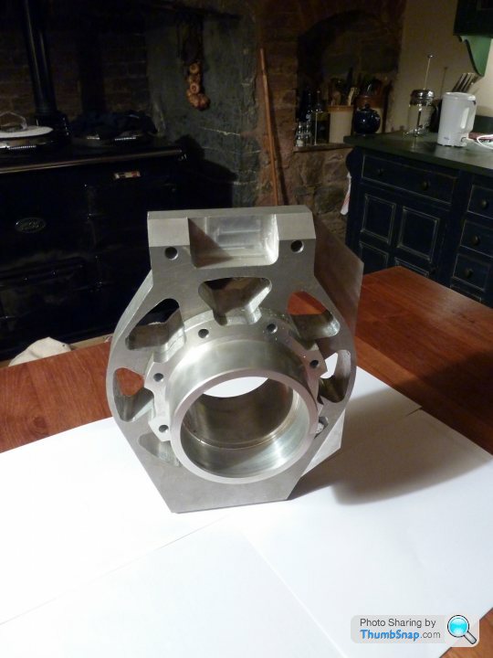
Halfway through machining one half of a front upright at the mo. Awaiting delivery of a larger bore guage for checking the bearing seat as my current ones do not go large enough. Cant see my shed floor for all the aluminium swarf!!
Any chance of some pics of the 962 bodywork AtomicRex??
Any chance of some pics of the 962 bodywork AtomicRex??
Hi Rob,
I noticed that the bolt holding the outer heim joint of the lower front LCA to the upright is in single shear. Fair bit of braking force there, no? You could mod the upright and extend it down a bit and have the heim joint inside the upright, bolt through the outer "layer" of 6083-T6, through the heim joint and into the inner "layer." Same for the shock push/pull rod attachment @ the bot. of the upright.
Also, for cost, if you plan to, as you mentioned use shims for camber adjustment, couldn't you use bronze or another type of bushing at the chassis side of the UCA instead of the heims, have a welded UCA and use only one heim @ upright?
I'm not trying to be a jerk, I hope you don't mind me mentioning these things.
What's your target weight?
Who/What/Where's the rack from?
Hope you get some money back from recycling all that swarf
Awesome project!
B
On edit: how do you plan to keep the noise down on the road legal car?
Edited by Slow M on Friday 26th February 07:08
No probs at all with you mentioning things. I thinks its good for all on here to express their own views.
Yes the lower control arm upright pivot is in single shear. The geometry I put together mandates having this point as low as possible, very close to the rim itself. I would probably be able to sqeak in another plate thickness at the lower end but the added complication comes when steering the wheel. The control arm tubes themselves will come very close to the drop down plates supporting the second bolt through plate unless they are widely spaced. To cut a long story short I just could not get enough material in there to have any significant improvement in strength. The other option I also considered was using a high angular misalignment bearing mounted with it centreline running fore/aft on the car but once again, when steering the wheel, extra clearance was required either side of the joint to clear the control arm. This then meant the two, now vertical, bolt through sections would have to quite widely spaced placing large bending moment on the bolt.
After much consideration I decided on my current design. I calculated and specced a larger spherical bearing along with the respective fixing bolt at this point so that even if any preload through the joint were released it will still be able to cope with the shear and bending resulting from cornering, braking etc. whilst maintaining a healthy safety factor against yield.
I will be able to adjust castor and also make adjustments to the anti-dive characteristics of the front end which requires me to use the spherical bearing inboard aswell
Target weight 800kg, Rack from Titan motorsport (custom made)
Cheers
Rob,
Where will you mount the fuel tank(s)?
Are you using Solidworks to calculate your chassis rigidity?
What sort of numbers are you getting for torsional rigidity?
Have you looked at this study?
Also, there is a great thread on another forum wherein people discuss and critique their (road racing) roll cage designs and I thought it might be of some interest to you.
Have you looked at reversing the triangulation members next to the passenger compartment so that they start at the base of the roll hoop, go to the center of the outrigger and back to the base of the A pillar and turning the adjacent triangulation in the vertical plane upside down? Would this have a large negative effect on beam stiffness? I'm wondering if this would make your chassis, which already looks very safe, even safer for the occupants.
One thing that comes up a lot in various discussions about roll cages is the benefit of "taco" gussets. have you considered the use of these at either side of the roof bar connecting front and rear roll hoops? Anywhere else?
Best,
B
Where will you mount the fuel tank(s)?
Are you using Solidworks to calculate your chassis rigidity?
What sort of numbers are you getting for torsional rigidity?
Have you looked at this study?
Also, there is a great thread on another forum wherein people discuss and critique their (road racing) roll cage designs and I thought it might be of some interest to you.
RobBiggs said:
...I will be able to adjust castor and also make adjustments to the anti-dive characteristics of the front end which requires me to use the spherical bearing inboard aswell...
I thought if you spaced the chassis tabs far enough apart, the distance between the "A"arm pivot and the chassis tabs could still give you castor adjustment (albeit to a lesser degree) by moving spacers fore and aft of the pivots inside the chassis tabs while lowering your production cost. Camber could still be adjusted by turning the outer heim joint in or out. Have you looked at reversing the triangulation members next to the passenger compartment so that they start at the base of the roll hoop, go to the center of the outrigger and back to the base of the A pillar and turning the adjacent triangulation in the vertical plane upside down? Would this have a large negative effect on beam stiffness? I'm wondering if this would make your chassis, which already looks very safe, even safer for the occupants.
One thing that comes up a lot in various discussions about roll cages is the benefit of "taco" gussets. have you considered the use of these at either side of the roof bar connecting front and rear roll hoops? Anywhere else?
RobBiggs said:
mp62 - As Paul correctly stated, althought the steering arms in my design to run at an angle, they are the same length as and do run paralell to the upper control arms meaning there will be no bump steer. The basic theory behind setting up a geometry for zero bump steer is that the upper and lower control arms and the steering link all converge and intersect about a common instant centre. I am using this design so that i can adjust static geometry such as camber by adding or removing shims from behind the common mount for the top link and steering link without affecting bump steer at all.
While I can see this to be true under braking/front to rear load transfers or bump/droop in strady state forward travel, won't there still be some small amount of bump steer with the wheels turned as, in that scenario, the instant centers move apart? Best,
B

B,
There will be twin fuel tanks, one on either side of the car just ahead of the rear wheel side ducts.
I've spent a lot of time working on the spaceframe. I've used numerous programs to model and develop the design, one of them being COSMOSWorks (built into Solidworks), but also: 'Grape', FrameWork' and finally one very laborious hand calculation using the Energy Method. Current torsional stiffness values lie at the 25,000Nm/degree mark although this does not include the affects of the riveted aluminium panelling that will be present in the cockpit. I therefore expect the final values to be higher again.
Many thanks for your pointers and links, it is very difficult to get hold of useful information on other designs. I don't think reversing the triangulations as you mention would affect stiffness and thinking about it, yes it would prob make sense to invert the ones in the horizontal plane so they form more of a bridge shape around the occupants. I have put much consideration into the safety aspects of my design. I could have made the chassis half the weight it is now but I would be worried about it being a little bit too flimsy in the event of a crash! Current weight is around 120-125kg so its still not that heavy though...
I have been debating whether or not to add some gussets to the roll hoops. I see no point in using them anywhere else on my frame since all other tubes meet at nodal points to form a fully triangulated structure. All suspension loads are fed into these nodal points. I.e. all tubes see only compressive/tensile loads and no bending moments. The front roll hoop and connecting tube however are an add-on that cannot realistictly be triangulated and will see large bending moments so I may well be using them here. Are you familiar with their construction? I am assuming they will be similar wall thickness to the tubing, bent over a circular mandrel?
As regards the front suspension, yes the bump steer characteristics are altered when a steering angle is introduced. However, with careful rack positioning fore/aft and by experimenting with different steering lever arm lengths I have manged to reduce this to a minimum. I'm talking about 0.05 degree of toe variation throughout all vertical wheel travel a full lock (around 30 degrees on the inside wheel) reducing down to 0.001 degree of toe variation at a more likely maximum for the track of 10 degrees
I agree I could use your method to adjust castor quite easily but adjusting anti-dive would be more difficult without have a setup that had slots for mounting points making it more difficult to set up. Ultimately I could go the more simplistic route once I've tested and setup the car but for this prototype I'm making most characteristics adjustable so I can play with the handling. I was rightly/wrongly assuming adjustable geometry would be a good thing for someone purchasing atrack-orientated car but maybe a more simplistic route would be better. It all depends what people want??
B, if you don't mind me asking what is your background? You seem like a more 'tech' guy as well as (I assume) being a car nut Do you have any projects of your own?
Cheers
There will be twin fuel tanks, one on either side of the car just ahead of the rear wheel side ducts.
I've spent a lot of time working on the spaceframe. I've used numerous programs to model and develop the design, one of them being COSMOSWorks (built into Solidworks), but also: 'Grape', FrameWork' and finally one very laborious hand calculation using the Energy Method. Current torsional stiffness values lie at the 25,000Nm/degree mark although this does not include the affects of the riveted aluminium panelling that will be present in the cockpit. I therefore expect the final values to be higher again.
Many thanks for your pointers and links, it is very difficult to get hold of useful information on other designs. I don't think reversing the triangulations as you mention would affect stiffness and thinking about it, yes it would prob make sense to invert the ones in the horizontal plane so they form more of a bridge shape around the occupants. I have put much consideration into the safety aspects of my design. I could have made the chassis half the weight it is now but I would be worried about it being a little bit too flimsy in the event of a crash! Current weight is around 120-125kg so its still not that heavy though...
I have been debating whether or not to add some gussets to the roll hoops. I see no point in using them anywhere else on my frame since all other tubes meet at nodal points to form a fully triangulated structure. All suspension loads are fed into these nodal points. I.e. all tubes see only compressive/tensile loads and no bending moments. The front roll hoop and connecting tube however are an add-on that cannot realistictly be triangulated and will see large bending moments so I may well be using them here. Are you familiar with their construction? I am assuming they will be similar wall thickness to the tubing, bent over a circular mandrel?
As regards the front suspension, yes the bump steer characteristics are altered when a steering angle is introduced. However, with careful rack positioning fore/aft and by experimenting with different steering lever arm lengths I have manged to reduce this to a minimum. I'm talking about 0.05 degree of toe variation throughout all vertical wheel travel a full lock (around 30 degrees on the inside wheel) reducing down to 0.001 degree of toe variation at a more likely maximum for the track of 10 degrees
I agree I could use your method to adjust castor quite easily but adjusting anti-dive would be more difficult without have a setup that had slots for mounting points making it more difficult to set up. Ultimately I could go the more simplistic route once I've tested and setup the car but for this prototype I'm making most characteristics adjustable so I can play with the handling. I was rightly/wrongly assuming adjustable geometry would be a good thing for someone purchasing atrack-orientated car but maybe a more simplistic route would be better. It all depends what people want??
B, if you don't mind me asking what is your background? You seem like a more 'tech' guy as well as (I assume) being a car nut
Do you have any projects of your own?Cheers
RobBiggs said:
...Current torsional stiffness values lie at the 25,000Nm/degree mark although this does not include the affects of the riveted aluminium panelling that will be present in the cockpit. I therefore expect the final values to be higher again...Current weight is around 120-125kg so its still not that heavy though...
Rob, That's just phenomenal!!!
RobBiggs said:
...front roll hoop and connecting tube however are an add-on that cannot realistictly be triangulated and will see large bending moments so I may well be using them here. Are you familiar with their construction? I am assuming they will be similar wall thickness to the tubing, bent over a circular mandrel?
Have a look at http://www.nasaproracing.com/rules/ccr.pdf section 11.4.7 "should be mandrel bends" and then 15.6, especially 15.6.10. Also, http://cms.scca.com/documents/Club%20Forms/2010%20... section 9.4 has some information on requirements. You may want to try to narrow down what sanctioning body/class you'd want to run the car(s) with and have a look at their safety requirements. RobBiggs said:
I'm talking about 0.05 degree of toe variation throughout all vertical wheel travel a full lock (around 30 degrees on the inside wheel) reducing down to 0.001 degree of toe variation at a more likely maximum for the track of 10 degrees
Again, that's spectacular!RobBiggs said:
B, if you don't mind me asking what is your background? You seem like a more 'tech' guy as well as (I assume) being a car nut Do you have any projects of your own?
I don't mind at all. Yes, 40 years of my 46 as a car nut. I've only recently developed an interest in chassis and suspension development; mostly for the sake of understanding my 1975 M series TVR well enough to "improve" it. http://www.pistonheads.com/gassing/topic.asp?h=0&a... Do you have any projects of your own?I'm looking forward to more updates from you.
I think that, once you're comfortable with the car in its turbo rotary guise, if you could show that it can take huge torque loads from a (maybe even turbo) LS motor, your product's marketability will skyrocket.
Best,
B
I believe that chassis was made by Derek smith who builds Porsche 962 Group C replicas in Canada.
Very nice chap I used to speak to quite regularly when I was looking to put together my own Group C car.
Some more:
http://www.ey3ltd.co.uk/porsche.html
http://www.gurneyflap.com/gtprototypes962.html
http://www.gtreproductions.com/GTR962.htm
Derek Smith's page (you will like!): http://members.shaw.ca/p962/p2.html
Enjoy!
Rob,
How's the Ackerman steering with that layout?
I had a thought for you where the windshield is concerned.
The race car had a large MAZDA decal covering the top of the windshield.
Maybe you can have this (quasi dome shape) be part of the body and make the remaining bottom section, as that looks like a simple curve, from glass.
Also, Have you thought of contacting the people who have this site and asking if they would share the body drawings with you? http://www.geocities.co.jp/SiliconValley-Bay/1322/... click the link below the white text box.
B
Good idea for the windscreen. I agree, a curved window profile is most definitely going to be easier and far cheaper to produce than a domed one. I will be making a heat-formed polycarbonate screen for the prototype and then once I am happy with the shape and design I will be getting a mould produced and have a glass one made.
The Ackerman in this setup is minimal. I am of the opinion (as per suspension design reference books) that ackerman becomes less of a reuirement as the car has more cornering potential. It basically comes down to slip angles and the fact that the outside wheel will be taking more of the cornering load and as a result will need fractionally more steering lock compared to the inside wheel.
I've been busy making parts from my aluminium billets these last few weeks and things are coming along. For more pics etc, see my blog http://groupcreplica.blogspot.com/

RobBiggs said:
The Ackerman in this setup is minimal. I am of the opinion (as per suspension design reference books) that ackerman becomes less of a reuirement as the car has more cornering potential. It basically comes down to slip angles and the fact that the outside wheel will be taking more of the cornering load and as a result will need fractionally more steering lock compared to the inside wheel.
I'm sure you're right about grip but do wonder about tire wear. Nice box of swarf BTW.
GREAT to see your progress.
B.
RobBiggs said:
All parts machined on a manual milling machine and lathe. Hoping to convert both machines to cnc soon!!
Impressive - I haven't machined by hand since I was at college, remember it being a laborious process. What are the combination of holes for on the back surface of the hub ?

Pictures here of all the Mazda race cars.
http://www.rotarycommunity.com/tt.aspx?forumid=193
http://www.rotarycommunity.com/photo.aspx?albumid=...
Plus I have a front section off 787b to take measurements from
http://www.rotarycommunity.com/tt.aspx?forumid=193
http://www.rotarycommunity.com/photo.aspx?albumid=...
Plus I have a front section off 787b to take measurements from
Gassing Station | Kit Cars | Top of Page | What's New | My Stuff