Mac#1 Motorsport Worx Build
Discussion


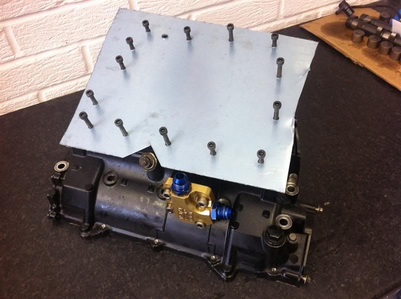
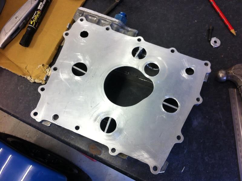
This afternoons task was to sort out a baffle plate to go between the engine and sump, I marked out and drilled the holes for the oil return and sump mounting bolts.
Here it is trial fitted to the engine to check hole spacings
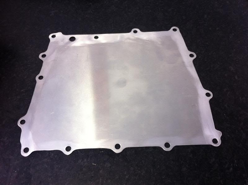
It was then trimmed down to the shape of the engine/sump
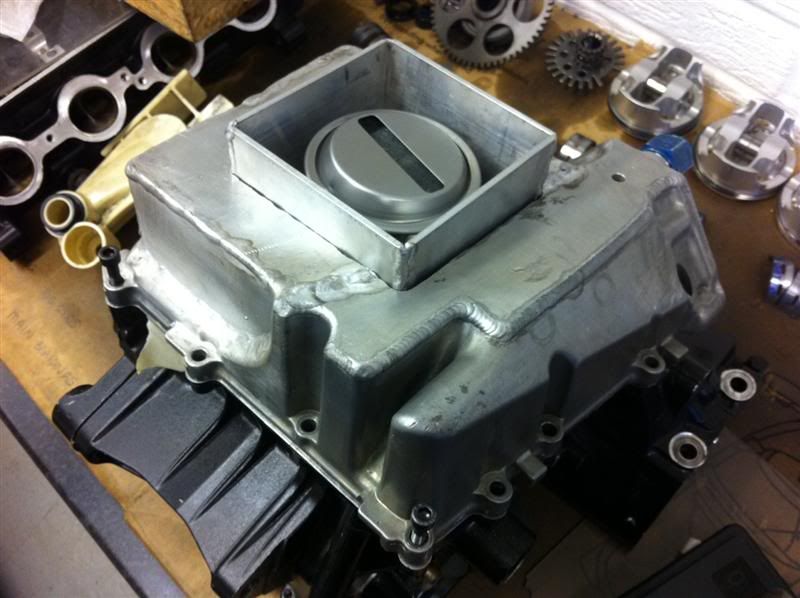
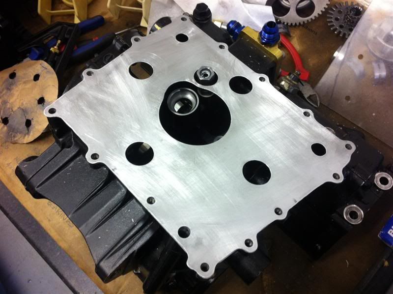
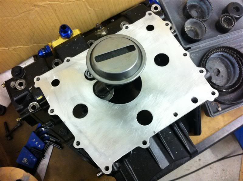
With it resting on the engine it looks like this
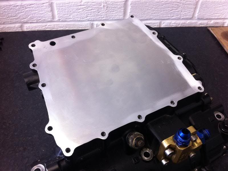
Once the sump baffles and oil pickup are finished I will add the necessary holes in the baffle plate to suit.
Here it is trial fitted to the engine to check hole spacings
It was then trimmed down to the shape of the engine/sump
With it resting on the engine it looks like this
Once the sump baffles and oil pickup are finished I will add the necessary holes in the baffle plate to suit.
Here's the latest installment of updates...
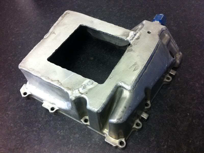
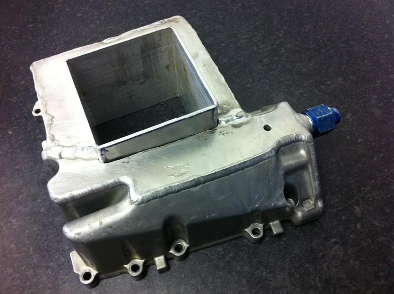
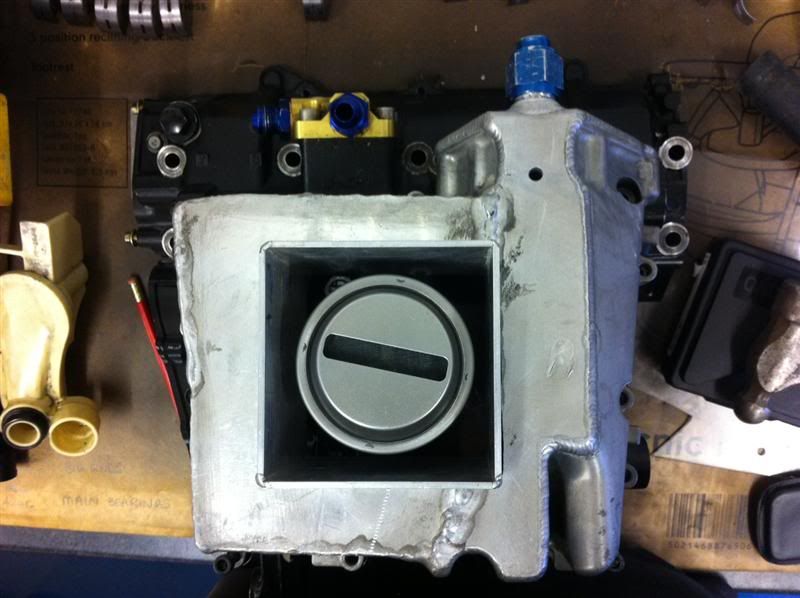
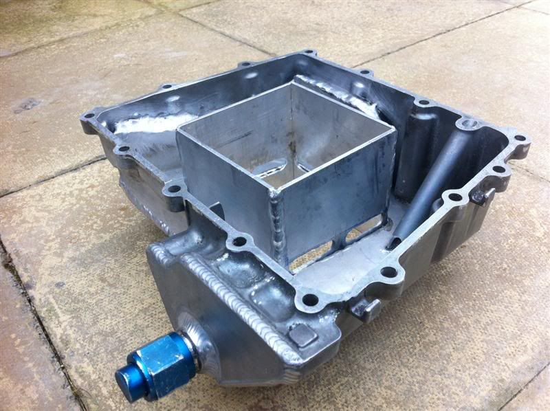
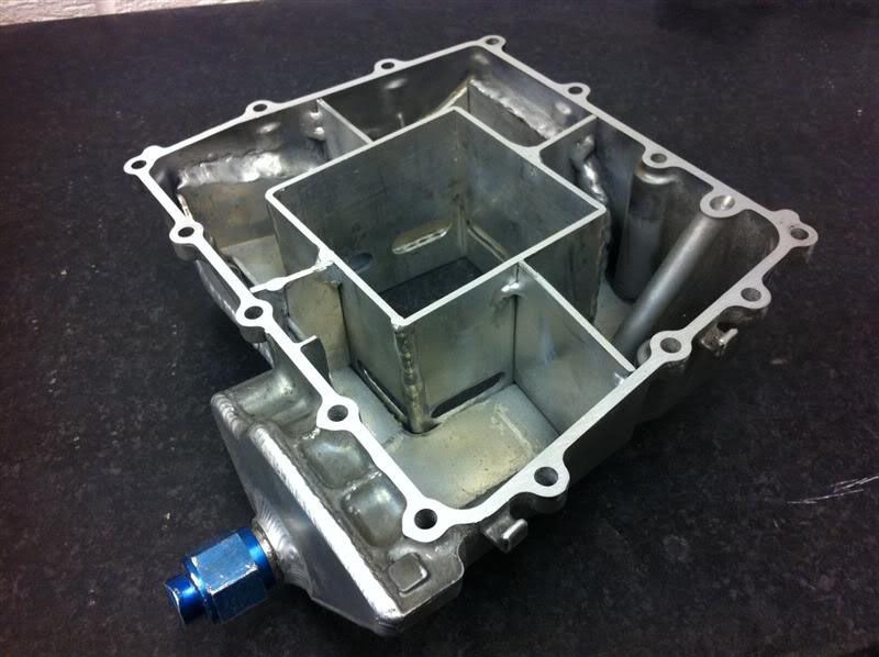
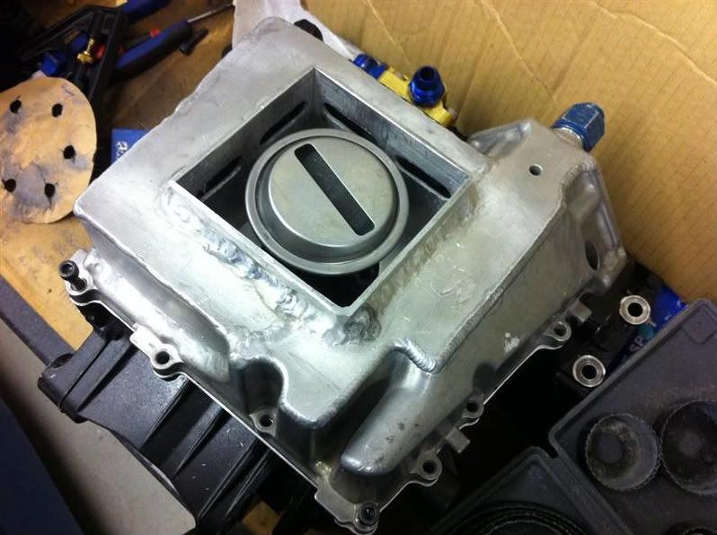
One baffle box for the centre of the sump.
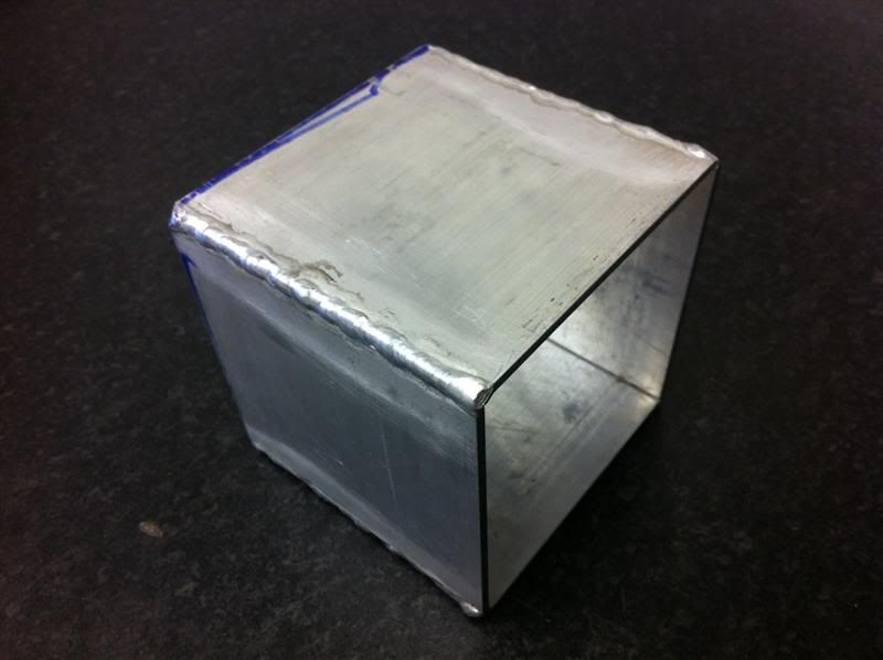
The sump was then cut to allow the baffe box to be fitted.
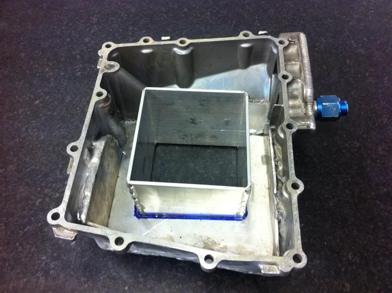
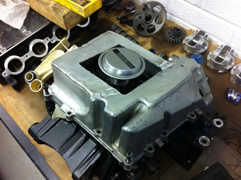
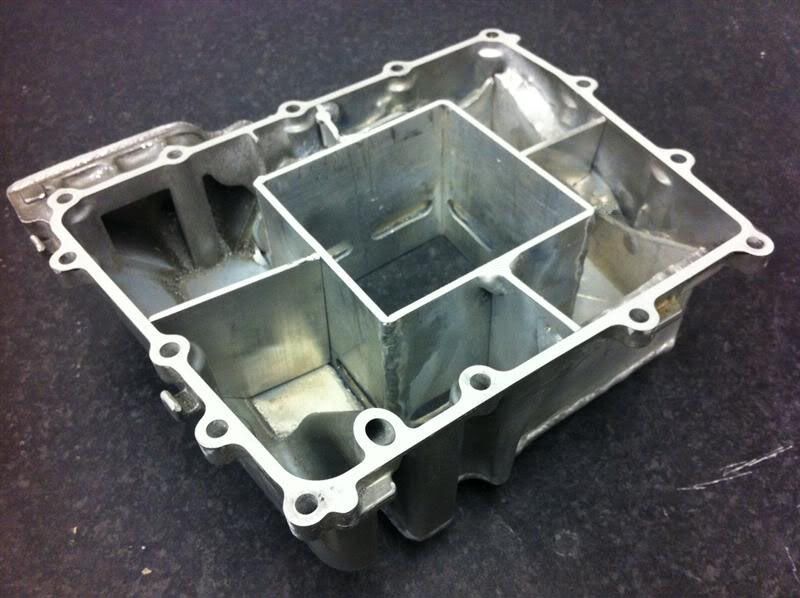
Here is roughly how it will look when assembled, although there will be extra baffle plates between the sump walls and the baffle box.
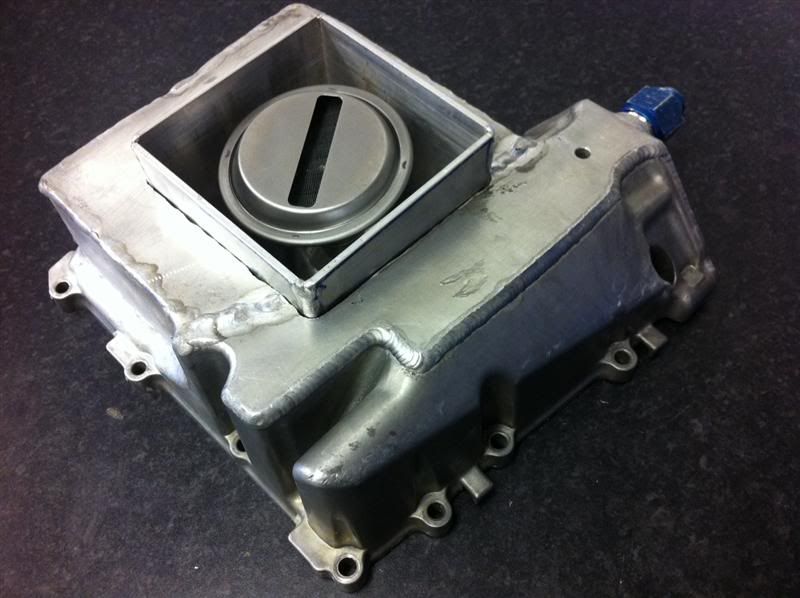
Once the pipework ha been fabricated, the Fireblade oil pickup will sit in the base of the sump something like this.
One baffle box for the centre of the sump.
The sump was then cut to allow the baffe box to be fitted.
Here is roughly how it will look when assembled, although there will be extra baffle plates between the sump walls and the baffle box.
Once the pipework ha been fabricated, the Fireblade oil pickup will sit in the base of the sump something like this.
I'm waiting on some tube being delivered to allow the sump to be progressed, so I decided to leave that and move onto the cylinder head.
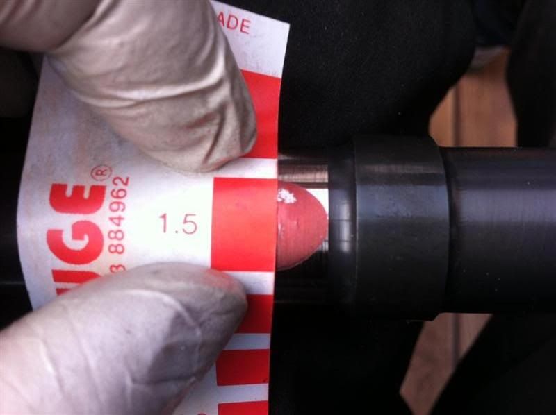
Before stripping the head I wanted to double check the cam journal to cap clearances, so strips of plastigauge were laid across the journals
All the cam caps were fitted, bolts torqued up and then removed, this crushed the plastigauge material, the clearances measured between 0.0015" and 0.002", whcih were within manufacturers recommendation of 0.0015" and 0.0032"
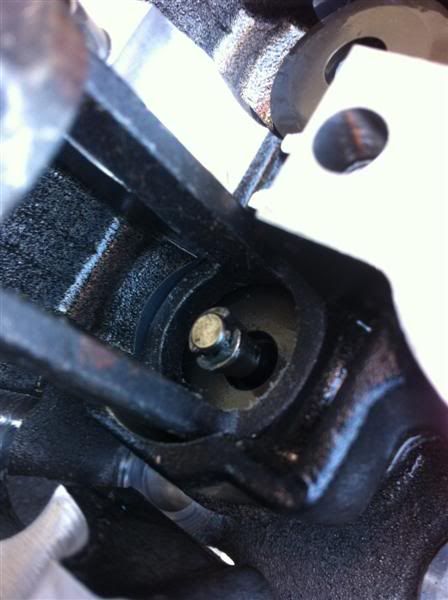
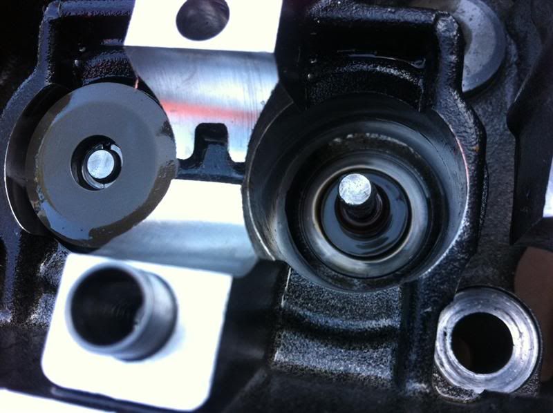
Next up was the task of removing the valves, a spring compressor was used to compress and hold the valve springs
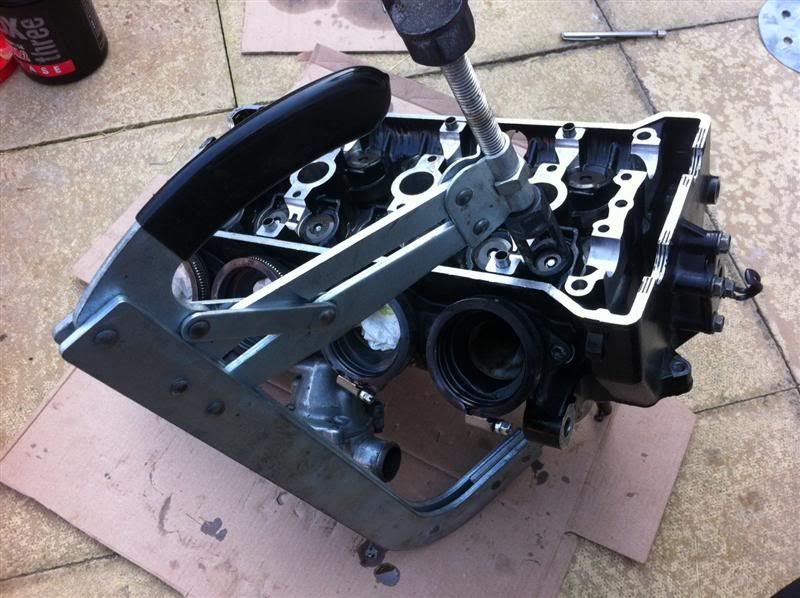
Here you can see the valve spring has been compressed and the securing collets are accessable
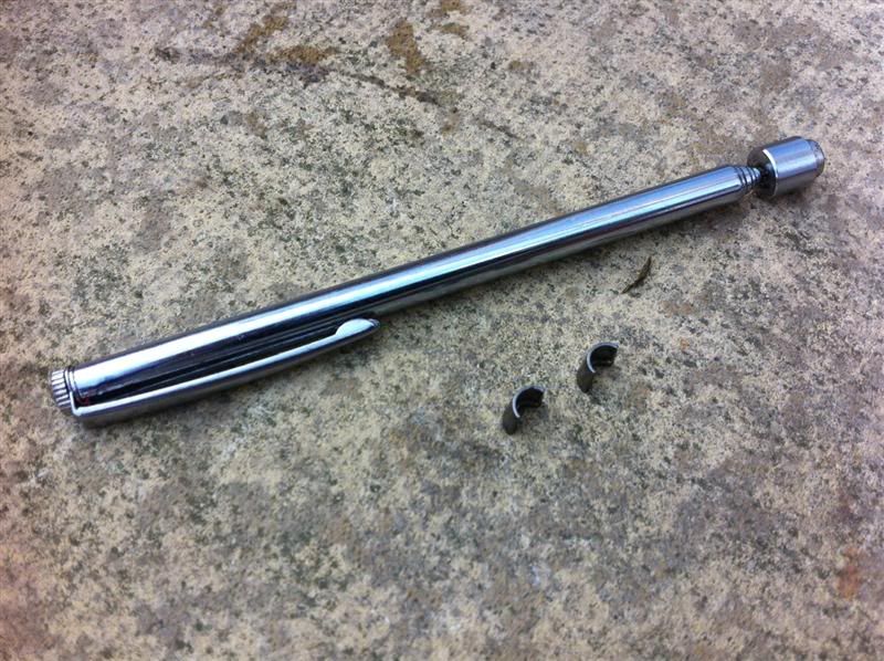
Using a telescopic magnet the collets were removed
With the valve spring compressor removed things look like this
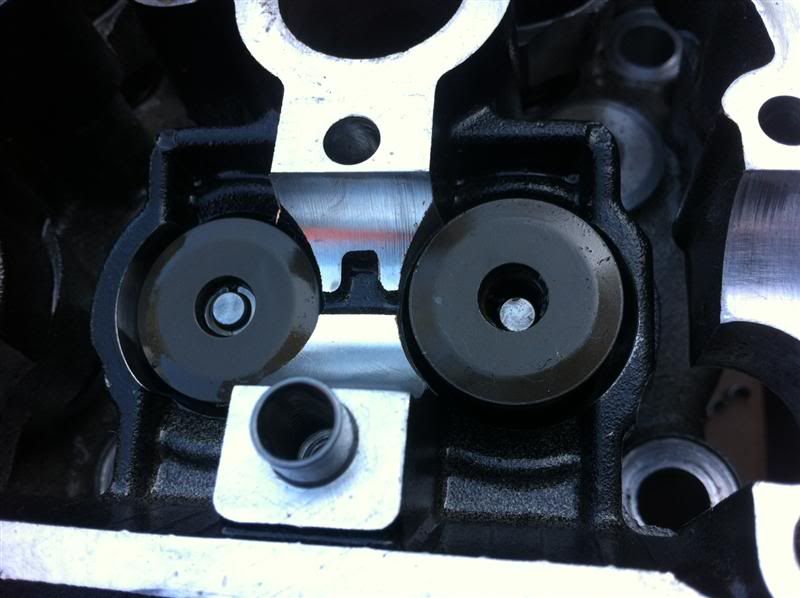
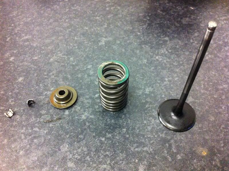
The valve spring retainer was then removed
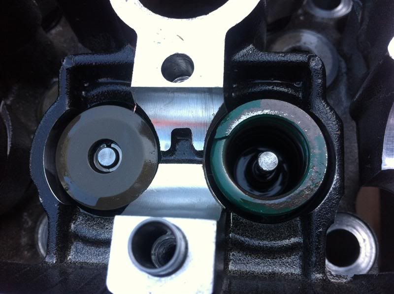
With the valve spring removed, you can see thevalve stem and valve stem oil seal
The valve them simply pushes out of the head.
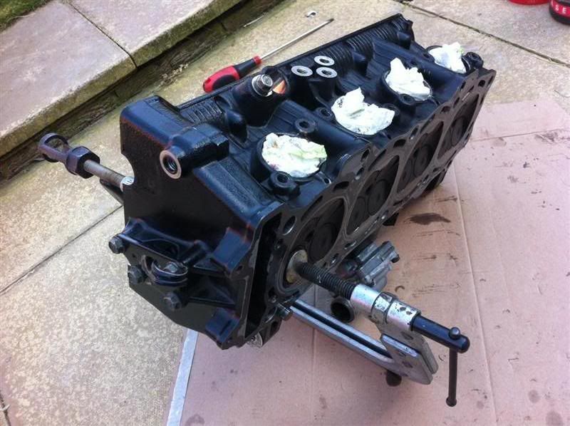
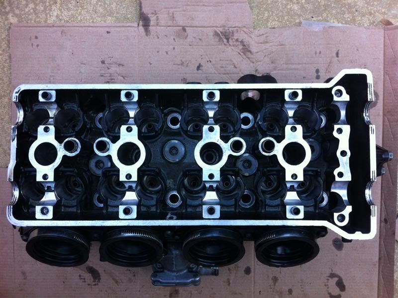
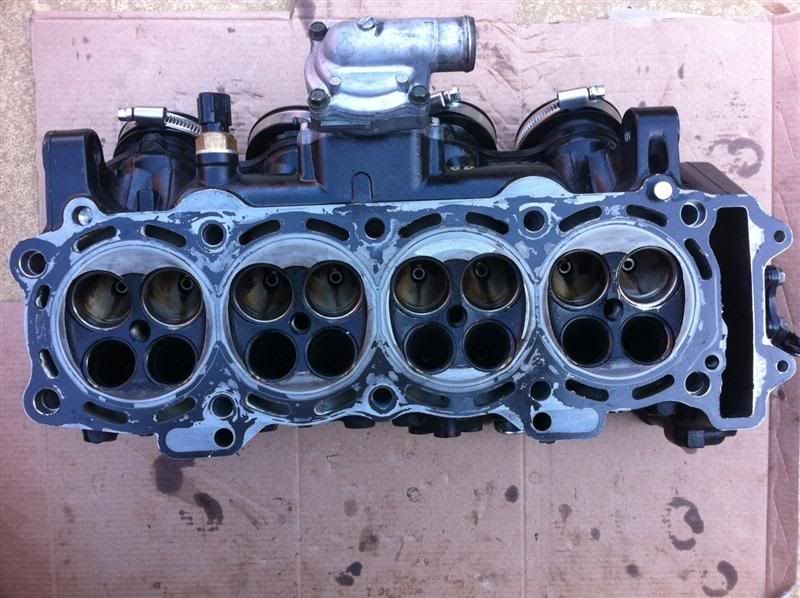
The bare cylinder head
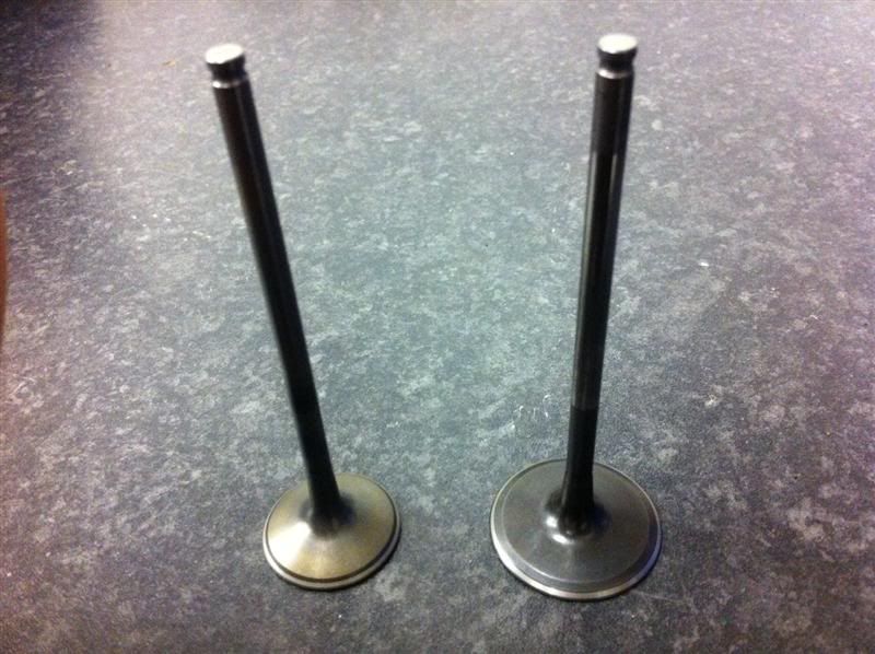
I cleaned all the deposits from the valves, here are a couple of before and after comparison photos
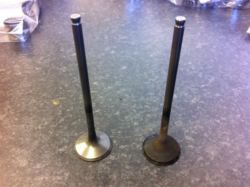
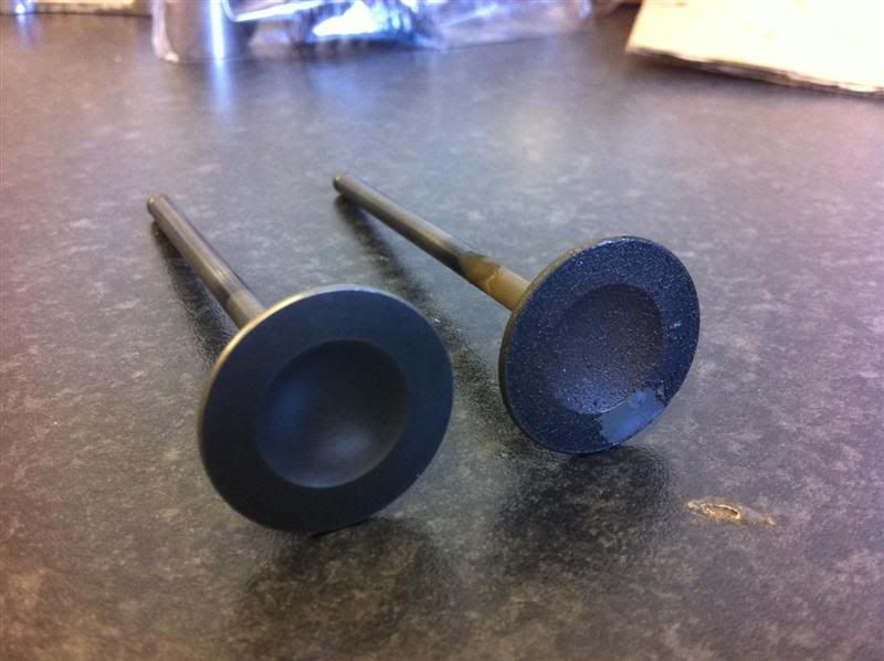
The valves stems were then measured, checked for damage/bending and llapped in with fine valve grinding paste
Before stripping the head I wanted to double check the cam journal to cap clearances, so strips of plastigauge were laid across the journals
All the cam caps were fitted, bolts torqued up and then removed, this crushed the plastigauge material, the clearances measured between 0.0015" and 0.002", whcih were within manufacturers recommendation of 0.0015" and 0.0032"
Next up was the task of removing the valves, a spring compressor was used to compress and hold the valve springs
Here you can see the valve spring has been compressed and the securing collets are accessable
Using a telescopic magnet the collets were removed
With the valve spring compressor removed things look like this
The valve spring retainer was then removed
With the valve spring removed, you can see thevalve stem and valve stem oil seal
The valve them simply pushes out of the head.
The bare cylinder head
I cleaned all the deposits from the valves, here are a couple of before and after comparison photos
The valves stems were then measured, checked for damage/bending and llapped in with fine valve grinding paste
I've had an update from APE Raceparts, my Carrillo rods and gaskets are in stock and have been sent out to me today.
AJ Suttons sent out my new oil pump, filter, and other parts, they arrived today.
I spoke to Chris Applebee the other day regarding my crankshaft being reground, unfortunately when he checked it over, the big end journal number 3 was worn but still within the limits of a regrind and new shells, however the crankshaft was bent around this area, so it is officially scrap!
I have a spot of good news though, I took delivery of this 2005 engine yesterday
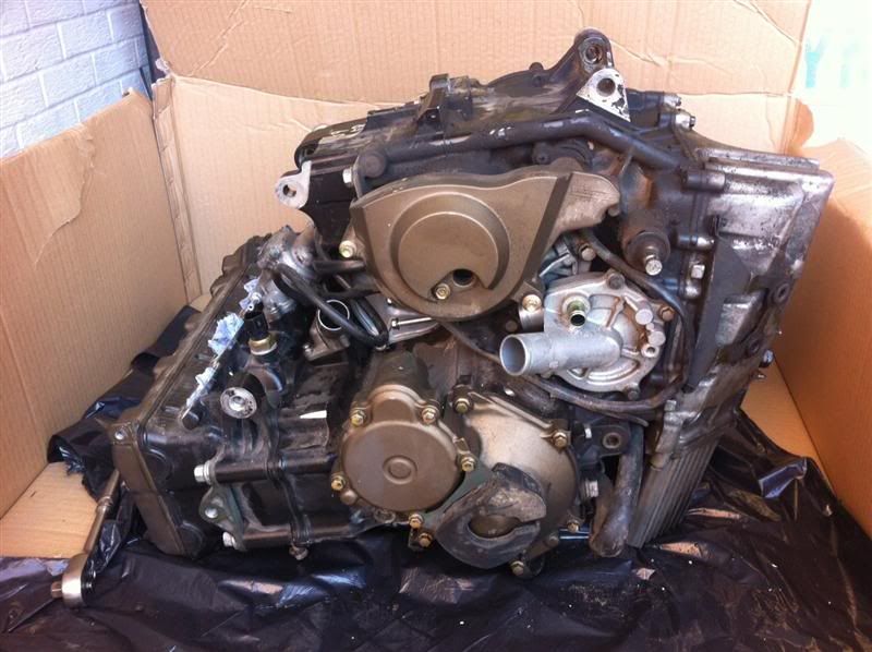
I spent this afternoon stripping it down to remove the crankshaft, the crankshaft has been measured up and bearing clearances checked with the old bearings fitted in my turbo engine, everything looks good.
That means tomorrows jobs list consists of assembling the cylinder head, checking valve clearances and ordering up some new main and big end shells and possibly some cam follower shims.
AJ Suttons sent out my new oil pump, filter, and other parts, they arrived today.
I spoke to Chris Applebee the other day regarding my crankshaft being reground, unfortunately when he checked it over, the big end journal number 3 was worn but still within the limits of a regrind and new shells, however the crankshaft was bent around this area, so it is officially scrap!
I have a spot of good news though, I took delivery of this 2005 engine yesterday
I spent this afternoon stripping it down to remove the crankshaft, the crankshaft has been measured up and bearing clearances checked with the old bearings fitted in my turbo engine, everything looks good.
That means tomorrows jobs list consists of assembling the cylinder head, checking valve clearances and ordering up some new main and big end shells and possibly some cam follower shims.
The engine took a back seat at first today while I cracked on with a spot of gardening  but once finished in the garden it was straight into the garage.
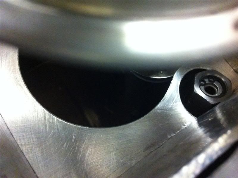
I bought some tubing on ebay earlier in the week, it arrived today so I was able to make some progress on the oil pickup.
The inside diameter of the standard oil pickup seal is larger than the required pipework for the oil pickup. A larger piece of tube was used as a sleeve and the tube for the oil pickup now slots inside this.
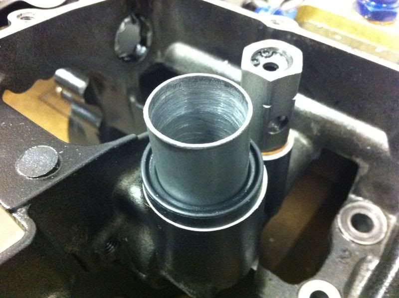
Here's the modified Fireblade oil pickup tacked together
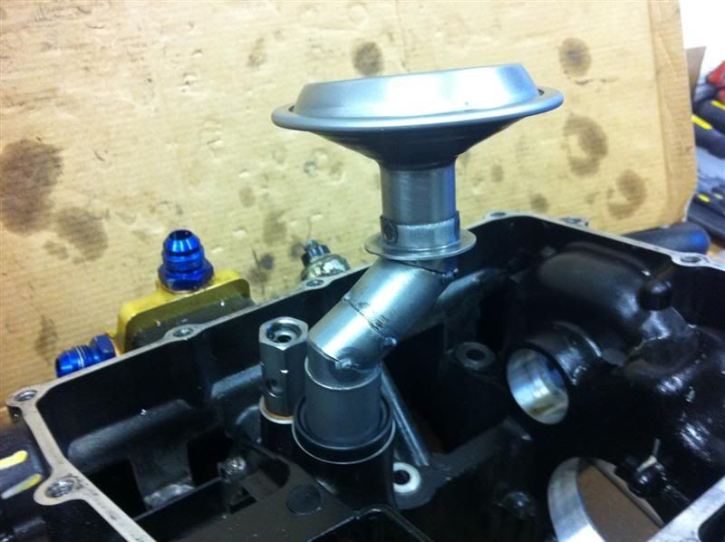
Here it is with the sump rested in position
Baffle rested roughly in position
The depth of the sump in the centre is still to be finalised, as is the oil pickup height, this is achievable because the sleeve is not welded to the pipework so the height is still able to be altered easily.
but once finished in the garden it was straight into the garage.I bought some tubing on ebay earlier in the week, it arrived today so I was able to make some progress on the oil pickup.
The inside diameter of the standard oil pickup seal is larger than the required pipework for the oil pickup. A larger piece of tube was used as a sleeve and the tube for the oil pickup now slots inside this.
Here's the modified Fireblade oil pickup tacked together
Here it is with the sump rested in position
Baffle rested roughly in position
The depth of the sump in the centre is still to be finalised, as is the oil pickup height, this is achievable because the sleeve is not welded to the pipework so the height is still able to be altered easily.
Ding dong... that's the sound of the postman! 
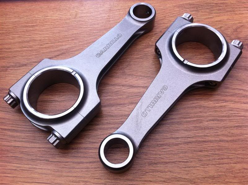
One set of H beam Carrillo con rods
In the con rod kit comes a bolt torque spec sheet, lubrication for the bolt threads and shoulders and some plastigauge for checking the bearing clearances.
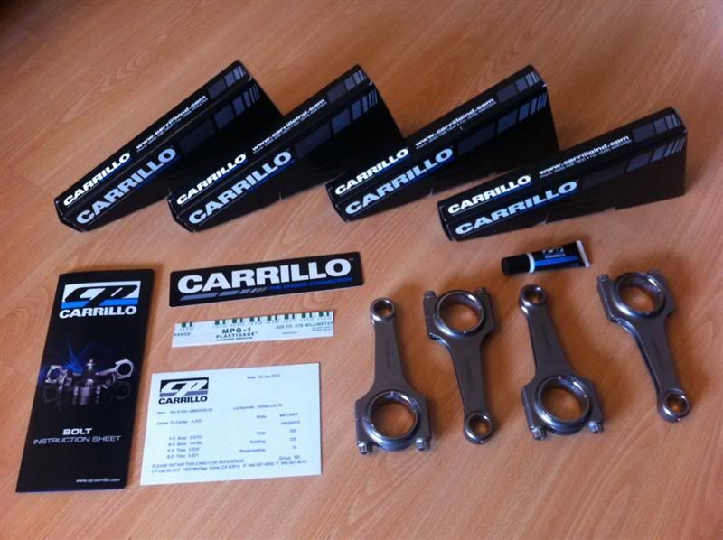
They were expensive but they look bloody fantastic and super strong!
And just for the hell of it, here's a close up photo of two of the rods
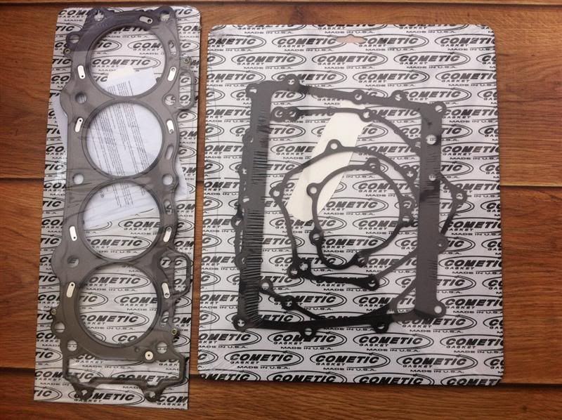
A Cometic multi layer steel head gasket and bottom end gasket set
One set of H beam Carrillo con rods
In the con rod kit comes a bolt torque spec sheet, lubrication for the bolt threads and shoulders and some plastigauge for checking the bearing clearances.
They were expensive but they look bloody fantastic and super strong!
And just for the hell of it, here's a close up photo of two of the rods
A Cometic multi layer steel head gasket and bottom end gasket set
You and me both Yazza 
Still waiting on the main and big end bearings coming into stock.
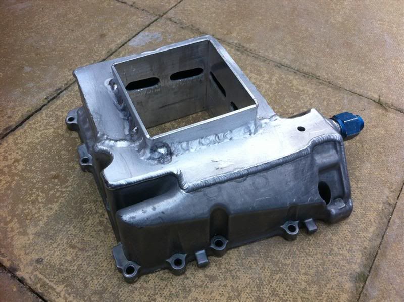
Here you can see the last of the sump baffle plates tack welded in position
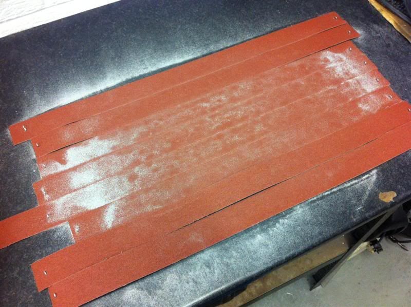
When i rested the sump on the engine casing for trial fitting it had warped slightly, so a few lengths of emery cloth were stapled to the work bench and the flange face was lapped back to flat.
Still waiting on the main and big end bearings coming into stock.
Here you can see the last of the sump baffle plates tack welded in position
When i rested the sump on the engine casing for trial fitting it had warped slightly, so a few lengths of emery cloth were stapled to the work bench and the flange face was lapped back to flat.
Quality work. I praise the way you have spent so much effort getting it completed, and then not being happy with a noise you have completly stripped it to resolve the problem. I am assume you have been a little anoyed with the situation but hats off for cracking on to get it fixed !!
Thanks for the encouraging comments, they definitely help to build the extra motivation needed to get it finished quickly!
This morning I checked the valve clearances.
The recommended Kawasaki clearances are,
Exhaust 0.17mm - 0.22mm (0.0067" - 0.0087")
Inlet 0.15mm - 0.24mm (0.0059" - 0.0094")
Here are some photos showing how I done it...
First off you'll need a set of feeler gauges, metric or imperial, it's entirely up to you
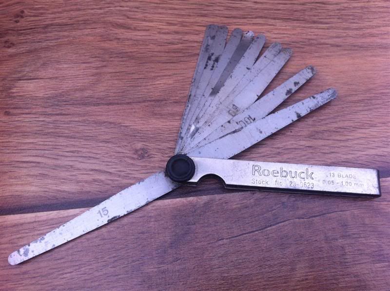
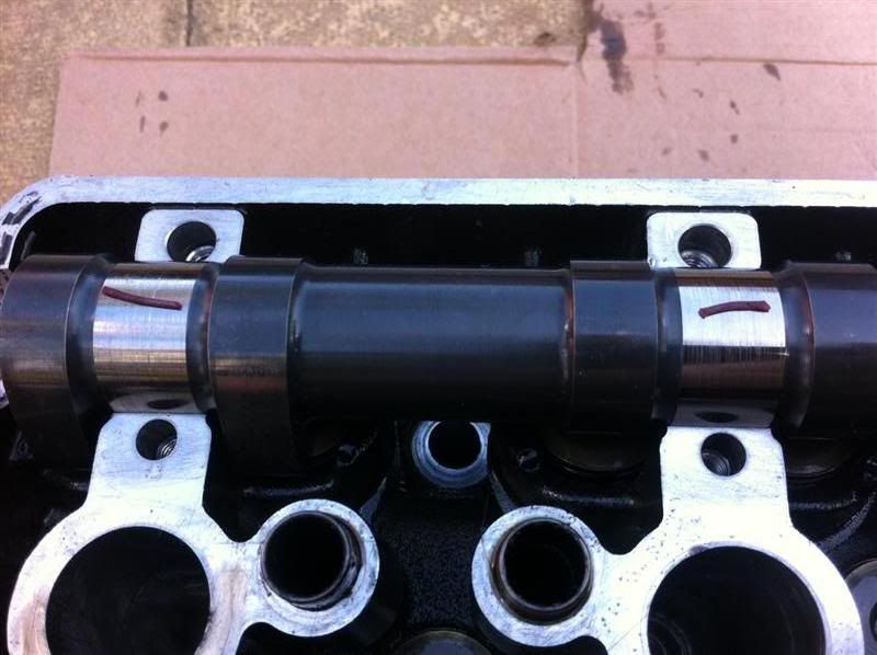
Set the cam lobe in this position for the clearance you wish to measure
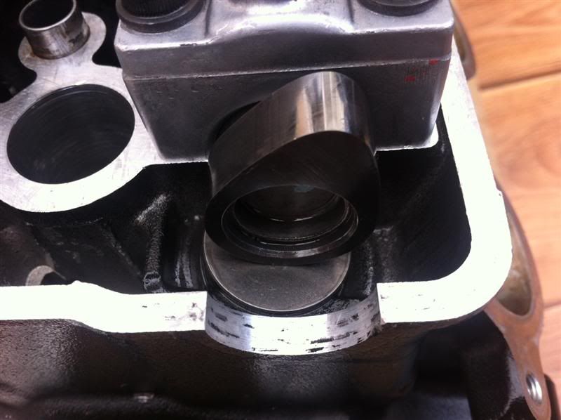
Slide the feeler gauge blade between the cam lobe and the cam follower, making a note of the largest feeler gauge blade you can fit in the gap, this is your valve clearance measurement.
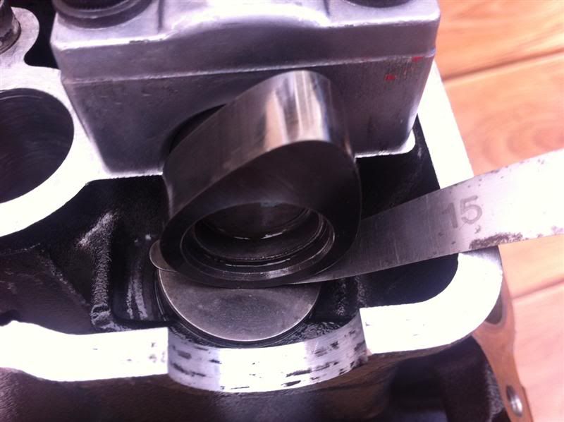
I measured the inlet clearances at 0.15-0.22mm and exhaust clearances at 0.18-22mm, they were all within tolerance, so no need to adjust them.
This morning I checked the valve clearances.
The recommended Kawasaki clearances are,
Exhaust 0.17mm - 0.22mm (0.0067" - 0.0087")
Inlet 0.15mm - 0.24mm (0.0059" - 0.0094")
Here are some photos showing how I done it...
First off you'll need a set of feeler gauges, metric or imperial, it's entirely up to you
Set the cam lobe in this position for the clearance you wish to measure
Slide the feeler gauge blade between the cam lobe and the cam follower, making a note of the largest feeler gauge blade you can fit in the gap, this is your valve clearance measurement.
I measured the inlet clearances at 0.15-0.22mm and exhaust clearances at 0.18-22mm, they were all within tolerance, so no need to adjust them.
Here's the oil pressure relief valve stripped down.
From left to right... circlip, spring retainer, spring, piston, housing
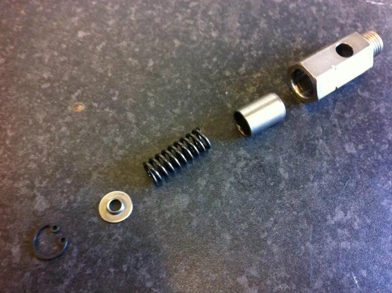
While it was stripped down i cleaned it up and rebuilt it, connected it to a compressor and tested it via an adjustable pressure regulator, it began leaking air immediately as the pressure was increased from 0psi and gradually leaked more and more until it held 70psi.
The relief valve was then stripped down again, fine valve grinding paste was applied to the piston which was then lapped in the housing, stripped and cleaned thoroughly. When retested it held pressure up to around 20psi then began to leak until it maintained 70psi of pressure. Much better than the first test.
The valve was stripped again and rebuilt with a standard M6 washer fitted between the circlip and the spring retainer, the thickness of the washer was measured at 1.55mm, this washer acts as a shim and increases the preload of the spring, thereby increasing the oil pressure setting of the relief valve. This time when tested it held pressure up to around 25-30psi then began to leak until it maintained 90psi of pressure.
This additional oil pressure should help to reduce the chance of bearing failure from low oil pressure at high RPM and make up for any pressure drops through my external oil lines and oil cooler. I'll be fitting an oil pressure guage too, so I can keep an eye on things.
From left to right... circlip, spring retainer, spring, piston, housing
While it was stripped down i cleaned it up and rebuilt it, connected it to a compressor and tested it via an adjustable pressure regulator, it began leaking air immediately as the pressure was increased from 0psi and gradually leaked more and more until it held 70psi.
The relief valve was then stripped down again, fine valve grinding paste was applied to the piston which was then lapped in the housing, stripped and cleaned thoroughly. When retested it held pressure up to around 20psi then began to leak until it maintained 70psi of pressure. Much better than the first test.
The valve was stripped again and rebuilt with a standard M6 washer fitted between the circlip and the spring retainer, the thickness of the washer was measured at 1.55mm, this washer acts as a shim and increases the preload of the spring, thereby increasing the oil pressure setting of the relief valve. This time when tested it held pressure up to around 25-30psi then began to leak until it maintained 90psi of pressure.
This additional oil pressure should help to reduce the chance of bearing failure from low oil pressure at high RPM and make up for any pressure drops through my external oil lines and oil cooler. I'll be fitting an oil pressure guage too, so I can keep an eye on things.
Red16 said:
It's an R-Tech 200A AC/DC set, I've had it about 5 months now, great service from R-Tech, I've used it a few times and I'm happy with it.
Here's a link to it on their website...
http://www.r-techwelding.co.uk/welding_equipment/T...
It's a good welder, I got mine from Kerf Developments ( http://www.kerfdevelopments.com/), I use it all the time, don't know how I got by without it!Here's a link to it on their website...
http://www.r-techwelding.co.uk/welding_equipment/T...
daniel22 said:
It's a good welder, I got mine from Kerf Developments ( http://www.kerfdevelopments.com/), I use it all the time, don't know how I got by without it!
Another happy customer Gassing Station | Kit Cars | Top of Page | What's New | My Stuff