3428TM Build Log
Discussion


Thanks Robert, thanks René.
Mads,
There will be a mesh inside, to stop stones from hitting following cars. This way, air flow from the trans tunnel will have a path, to escape, to minimize the drag added by the increase in cross-sectional area. A flat Aluminium air-dam, that roughly follows the curve of the top of the rear deck, and the rear fender extensions, will reduce lift, and I plan on CF venturi, and possibly a dismountable rear wing*, for track days.
Best regards,
Bernard.
* I have a folder of wing shapes, from the Lancia Group C effort, living somewhere, on my hard drive. Also, I have a couple of NACA/NASA wing shape generators, so should be able to come up with something effective.
Not really. I do have a plan, for underbody air flow management, that includes extracting radiator venting through the top of the hood, exhausting hot engine air at the rear of the hood, taking out the seat well recesses, and adding a flat sheet of Aluminium. To that end, I welded some DZUS tabs flush, with the bottom of the frame. There will be a front spoiler/diffuser, to redirect airflow, and reduce front lift. I think it's important, to clean the flow, underneath, in order to make use of it, and that the best way to utilize the air, is to guide it to the rear venturi.
What also makes it difficult, is the shape/size of off-the-shelf racing fuel cells, but I may end up doing without one of those, for a while.
Best regards,
Bernard.
What also makes it difficult, is the shape/size of off-the-shelf racing fuel cells, but I may end up doing without one of those, for a while.
Best regards,
Bernard.

Bernard,
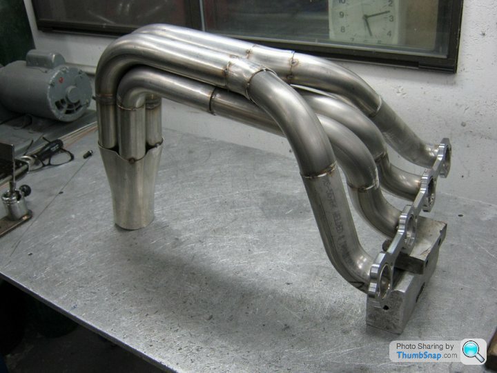
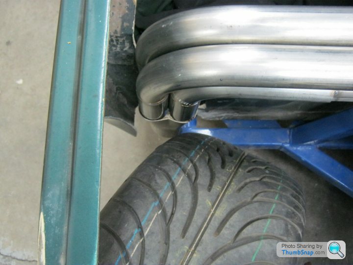
Where the the pipes come off the manifold turn up vertical then turn turn back horizontal there is a pipe diameter change.
It looks like the O/D of the initial pipe fits into the I/D of the pipes that run to the collector.
Is that a clever flow design feature or borne out of physical restraints?
Where the the pipes come off the manifold turn up vertical then turn turn back horizontal there is a pipe diameter change.
It looks like the O/D of the initial pipe fits into the I/D of the pipes that run to the collector.
Is that a clever flow design feature or borne out of physical restraints?

Hahaha! Thanks guys!
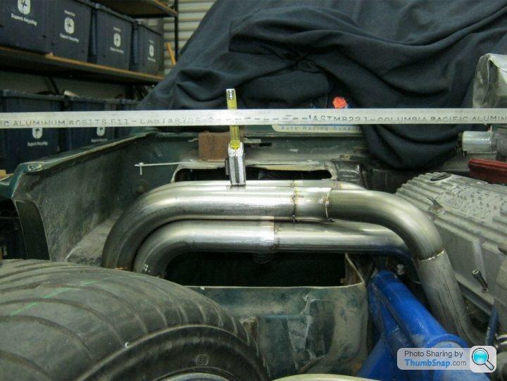
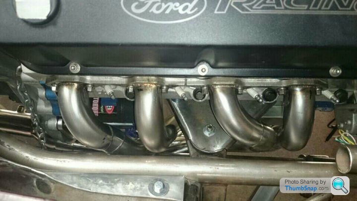
John, the exhaust ports don't leave a lot of space, for hardware*, and the exhaust fabricator insisted that there'd be no space left, for the bolt heads, if we started the primaries @ 1 3"/4" diameter. I asked my brother to revise the calculations, for a stepped header design, 1 5/8" into 1 3/4". Here is what he came up with, and by the way, there was zero loss, as compared with the earlier calculation:
--- for 331.646 CID from 4750 to 7250 RPM
--- 2-Step Primary Pipe Specs ---
1st Dia. inches= 1.609 Length= 13.9 to 15.2
2nd Dia. inches= 1.734 Length= 13.9 to 15.2
--- Header Collector Specs (Conventional Straight Tube) ---
Diameter= 2.969 to 3.219 Tuned Lengths= 16.2 best and also 8.1 or 32.3
--- Header Collector Specs (Megaphone or Diffuser Cone Shape) ---
Diameter= 2.469 taper to 3.469 Megaphone/Diffuser Length= 16.2 inches
Best HP/TQ Tuned Collector Lengths= 16.2 , 32.3 , 64.7 , 129.3 inches long
Worst HP/TQ Loss Collector Lengths= 24.2 , 48.5 , 97.0 , 194.0 inches long
Note-> all Pipe Diameters are OD and based-off .0625 inch Pipe thickness
Primary Pipe's Harmonics ----
1st Harmonic = 123.1 inches long ... typically never used
2nd Harmonic = 46.5 inches long ... longest recommended
3rd Harmonic = 27.8 inches long ... highly recommended , best Torque Curve
4th Harmonic = 19.3 inches long ... shortest recommended
5th Harmonic = 14.4 inches long ... typically never used
6th Harmonic = 11.3 inches long ... typically never used
7th Harmonic = 9.1 inches long ... typically never used
8th Harmonic = 7.5 inches long ... typically never used
Collector's Harmonics (includes Intermediate, Muffler , TailPipe) ----
1st Harmonic = 129.3 inches long ... longest with Mufflers and TailPipes
2nd Harmonic = 64.7 inches long ... longest recommended with Mufflers
3rd Harmonic = 32.3 inches long ... more bottom-end Torque
4th Harmonic = 16.2 inches long ... highly recommended , best Torque Curve
5th Harmonic = 8.1 inches long ... reduced Torque , more top-end HP sometimes
6th Harmonic = 4.0 inches long ... reduced Torque , not recommended
Best regards,
Bernard.
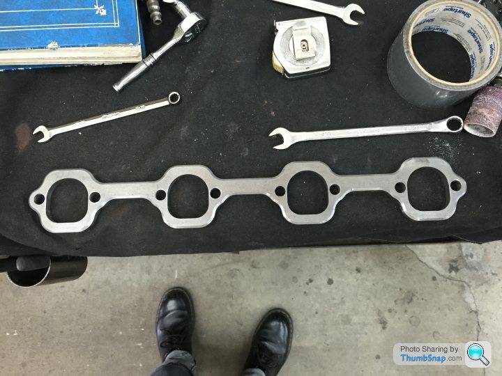
* the heads use standard SBF bolt spacing, and as you can see, from the above picture of the flange, the port is quite wide, compared to the stock Ford version.
John, the exhaust ports don't leave a lot of space, for hardware*, and the exhaust fabricator insisted that there'd be no space left, for the bolt heads, if we started the primaries @ 1 3"/4" diameter. I asked my brother to revise the calculations, for a stepped header design, 1 5/8" into 1 3/4". Here is what he came up with, and by the way, there was zero loss, as compared with the earlier calculation:
--- for 331.646 CID from 4750 to 7250 RPM
--- 2-Step Primary Pipe Specs ---
1st Dia. inches= 1.609 Length= 13.9 to 15.2
2nd Dia. inches= 1.734 Length= 13.9 to 15.2
--- Header Collector Specs (Conventional Straight Tube) ---
Diameter= 2.969 to 3.219 Tuned Lengths= 16.2 best and also 8.1 or 32.3
--- Header Collector Specs (Megaphone or Diffuser Cone Shape) ---
Diameter= 2.469 taper to 3.469 Megaphone/Diffuser Length= 16.2 inches
Best HP/TQ Tuned Collector Lengths= 16.2 , 32.3 , 64.7 , 129.3 inches long
Worst HP/TQ Loss Collector Lengths= 24.2 , 48.5 , 97.0 , 194.0 inches long
Note-> all Pipe Diameters are OD and based-off .0625 inch Pipe thickness
Primary Pipe's Harmonics ----
1st Harmonic = 123.1 inches long ... typically never used
2nd Harmonic = 46.5 inches long ... longest recommended
3rd Harmonic = 27.8 inches long ... highly recommended , best Torque Curve
4th Harmonic = 19.3 inches long ... shortest recommended
5th Harmonic = 14.4 inches long ... typically never used
6th Harmonic = 11.3 inches long ... typically never used
7th Harmonic = 9.1 inches long ... typically never used
8th Harmonic = 7.5 inches long ... typically never used
Collector's Harmonics (includes Intermediate, Muffler , TailPipe) ----
1st Harmonic = 129.3 inches long ... longest with Mufflers and TailPipes
2nd Harmonic = 64.7 inches long ... longest recommended with Mufflers
3rd Harmonic = 32.3 inches long ... more bottom-end Torque
4th Harmonic = 16.2 inches long ... highly recommended , best Torque Curve
5th Harmonic = 8.1 inches long ... reduced Torque , more top-end HP sometimes
6th Harmonic = 4.0 inches long ... reduced Torque , not recommended
Best regards,
Bernard.
* the heads use standard SBF bolt spacing, and as you can see, from the above picture of the flange, the port is quite wide, compared to the stock Ford version.

John, that's beautiful!
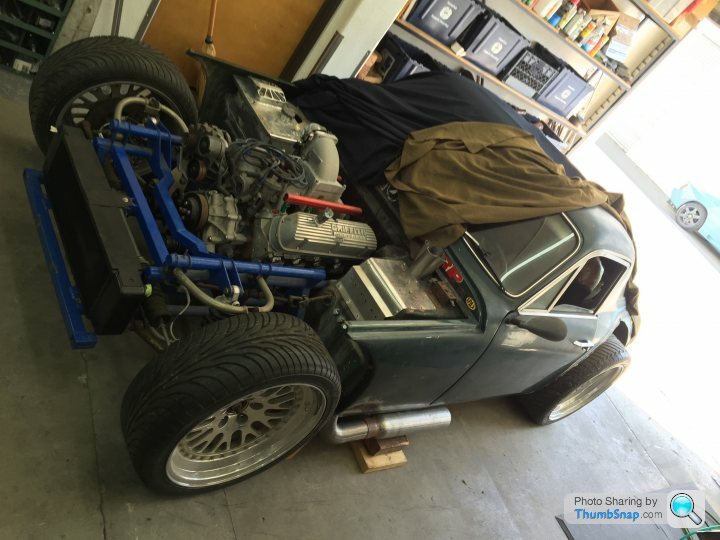
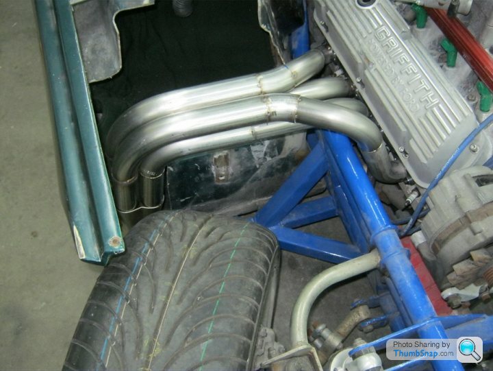
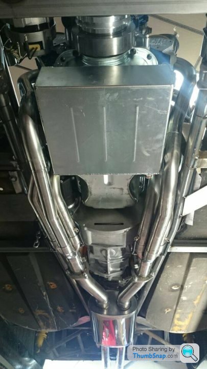
I have an additional spatial restriction, on the side of the starter; my behemoth Barnes dry sump pump is also there. When you add plumbing, there is not enough space left over, to route four individual pipes through.
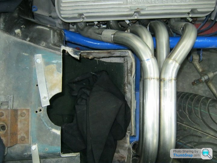
We also looked at doing something similar to the way the exhaust is routed on 90s Griffiths, but couldn't find the space, for the large vertical pipes, leading below.
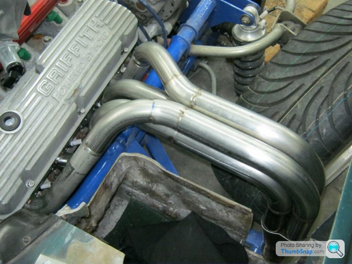
Side pipes were option three. What I like about this solution, is that there is no additional frontal area in the airstream. Bob, the exhaust builder, was able to get very close to equal length primary tubes. The aluminium belly pan I plan to install, should fit up easily, and have some degree of effectiveness. Additionally, the ground clearance is positively abundant. One down side, on an aesthetic level, is that whether I go for black or white high temperature exhaust coating, I will have to stencil on "CAUTION, HOT," in red.
Best regards,
Bernard.
I have an additional spatial restriction, on the side of the starter; my behemoth Barnes dry sump pump is also there. When you add plumbing, there is not enough space left over, to route four individual pipes through.
We also looked at doing something similar to the way the exhaust is routed on 90s Griffiths, but couldn't find the space, for the large vertical pipes, leading below.
Side pipes were option three. What I like about this solution, is that there is no additional frontal area in the airstream. Bob, the exhaust builder, was able to get very close to equal length primary tubes. The aluminium belly pan I plan to install, should fit up easily, and have some degree of effectiveness. Additionally, the ground clearance is positively abundant. One down side, on an aesthetic level, is that whether I go for black or white high temperature exhaust coating, I will have to stencil on "CAUTION, HOT," in red.
Best regards,
Bernard.
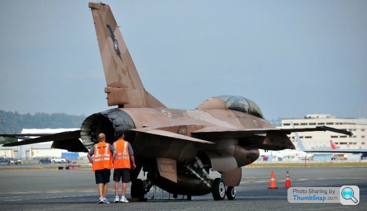
yup, in that american airforce stencil bernard..
Slow M said:
John, that's beautiful!
I have an additional spatial restriction, on the side of the starter; my behemoth Barnes dry sump pump is also there. When you add plumbing, there is not enough space left over, to route four individual pipes through.
We also looked at doing something similar to the way the exhaust is routed on 90s Griffiths, but couldn't find the space, for the large vertical pipes, leading below.
Side pipes were option three. What I like about this solution, is that there is no additional frontal area in the airstream. Bob, the exhaust builder, was able to get very close to equal length primary tubes. The aluminium belly pan I plan to install, should fit up easily, and have some degree of effectiveness. Additionally, the ground clearance is positively abundant. One down side, on an aesthetic level, is that whether I go for black or white high temperature exhaust coating, I will have to stencil on "CAUTION, HOT," in red.
Best regards,
Bernard.
chris52 said:
Must say your car is going to be a monster when it's finished. Great work Bernard it's one thing to restore a car it's a completely different job to re design it.
Chris
Chris, thanks! Chris
This is a proof of concept, to me, of what the upper limits are, of Mr. Bigland's design. I hope to not embarrass myself, or him. I sincerely feel the M series car's performance potential was left largely unexplored, and could have been developed to easily exceed its "exotic" contemporaries.
Best regards,
Bernard.

Gassing Station | TVR Classics | Top of Page | What's New | My Stuff