Tampolli SR2/LMP675 Full Ground Up Rebuild In Pictures
Discussion


That's a very nice NACA duct but I was wondering why you went down this route rather than the periscope type intake that was used with great success throughout the LMP900/675 era? Cars like the Audi R8 and R10, Peugeot 908 and Lola MG EX257 all used them for their turbo engines. Even Joest's final iteration of the 962 used periscopes. From my memory of Group C and LMP900 turbo cars the Saubers used NACA inlets - though to be fair they were pretty successful so you could well be onto something!
That's a good question.
I had been studying various cars to make the choice.
I needed to provide air flow to the following
Turbo inlet
Intercooler radiator
Rear brakes
I did consider the snorkel or periscope solution for the turbo inlet, as per this Jaguar below.
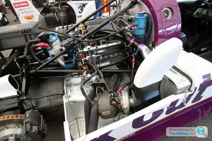
However it would break a very useful top surface.
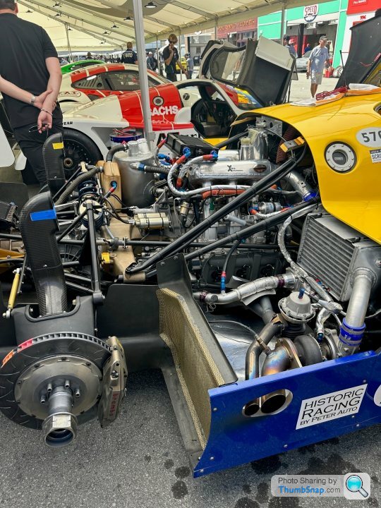
So decided to make use of the top surface of the rear clam for the NACA duct to feed the turbo and move the snorkel or periscope back to feed the brakes, as per the Porsche below.
In the following image you will see I have plenty of room in the top of half of the rear clam (not on car but you see the height to centre section) to incorporate the NACA duct filter/airbox.
I was lucky enough to be Rennsport 7 recently and spent a lot of time pouring over these cars and chatting to the technicians - it was very helpful.
Incidentally I am pulling air in off of the rear of the side pod surface to feed the intercooler radiator.
See the image below, showing funnel from the side mounted NACA duct under the exhaust.
Ultimately it just packages better in my installation.
I had been studying various cars to make the choice.
I needed to provide air flow to the following
Turbo inlet
Intercooler radiator
Rear brakes
I did consider the snorkel or periscope solution for the turbo inlet, as per this Jaguar below.
However it would break a very useful top surface.
So decided to make use of the top surface of the rear clam for the NACA duct to feed the turbo and move the snorkel or periscope back to feed the brakes, as per the Porsche below.
In the following image you will see I have plenty of room in the top of half of the rear clam (not on car but you see the height to centre section) to incorporate the NACA duct filter/airbox.
I was lucky enough to be Rennsport 7 recently and spent a lot of time pouring over these cars and chatting to the technicians - it was very helpful.
Incidentally I am pulling air in off of the rear of the side pod surface to feed the intercooler radiator.
See the image below, showing funnel from the side mounted NACA duct under the exhaust.
Ultimately it just packages better in my installation.
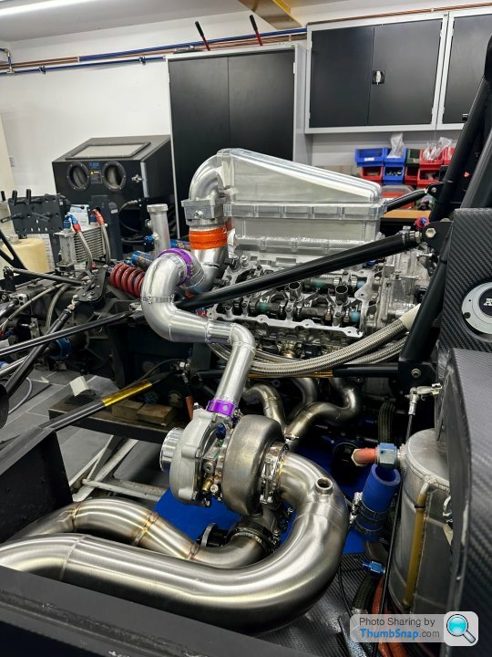
Some pictures from the building up of the induction end of the race motor.
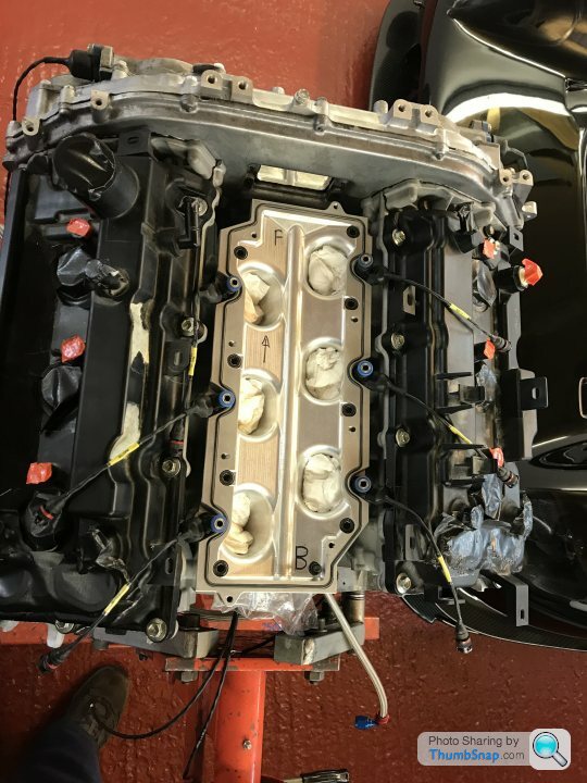
Lower intake installed, after each runner manually reworked to ensure perfect interface alignment with CNC port heads - there were minor discrepancies.
Note injectors are sandwiched between lower and upper intakes.
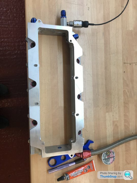
Adding some take off fittings to the upper intake (contains fuel rails) to allow for fuel regulator reference and manifold pressure sensor.
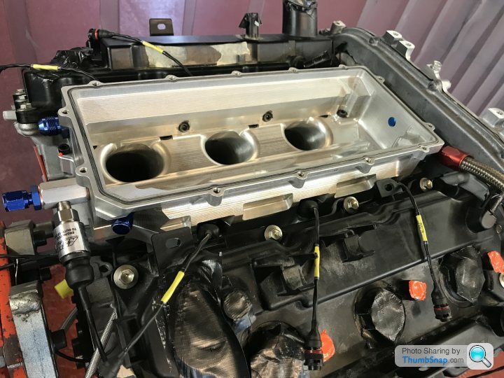
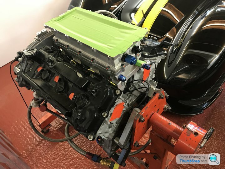
Upper intake installed.
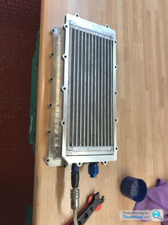
Pressure test the intercooler prior to fit.
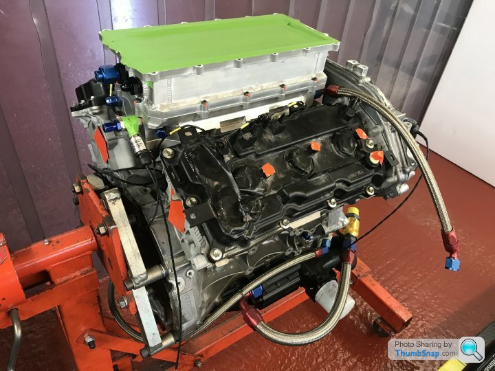
Intercooler fitted, protected and tell tails applied.
With engine nearing completion, time to complete the front brace and valve covers that form the top engine to bulkhead mount.
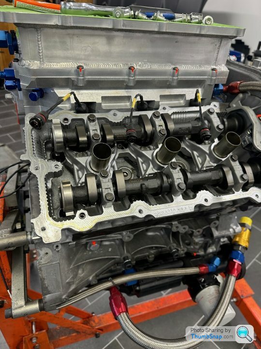
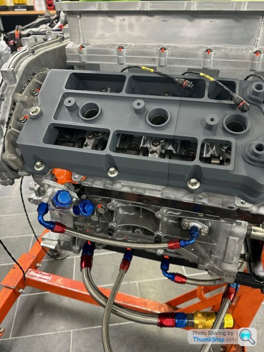
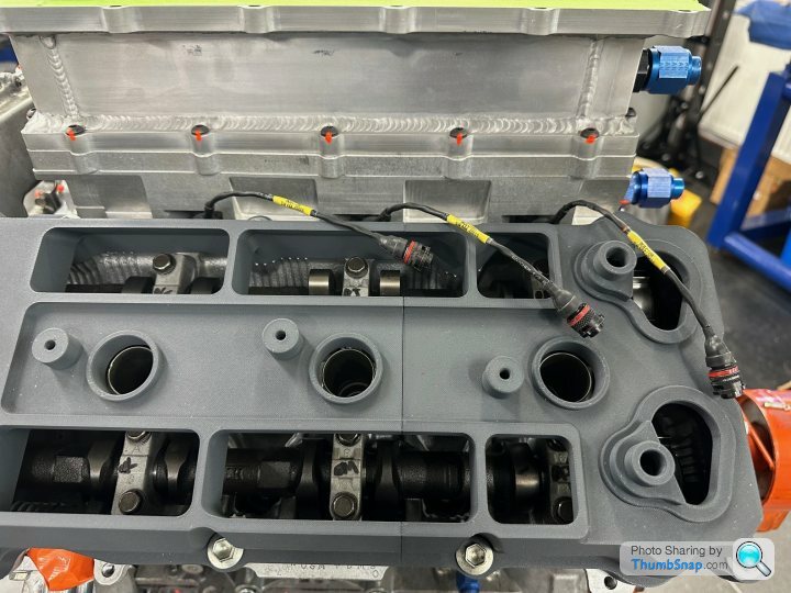
Temp valve covers removed, for test fit of 3D printed valve covers prior to sending to machine shop.
3D printed valve covers installed, note the slice through to review camshaft clearances (as high lift cams) - pretty happy, a couple of mods required internally to deal with some clearance issues on one of the ribs.
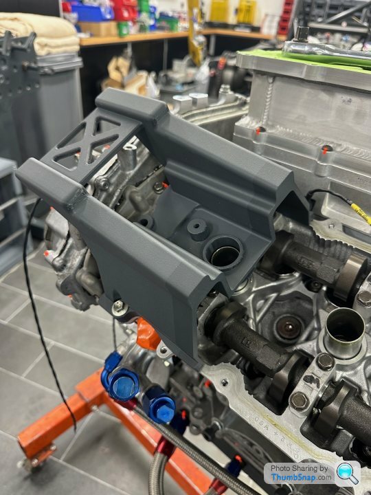
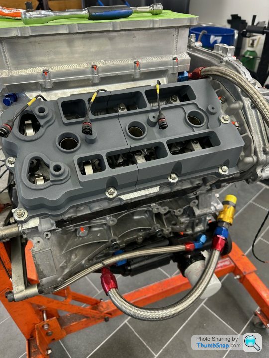
A different section of the 3D printed valve cover reviewing the front engine brace pick up points.
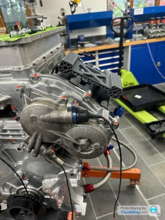
Again, pretty happy with the results the only adjustments needed are to the length of the lugs - which you can see I have manfully trimmed back to meet the front engine brace - will also need to adjust the lattice works between the lugs now they are shorter.
So next step is to modify the fusion models, reprint the 3d models for final test fit - then it is off to the machine shop.
Lower intake installed, after each runner manually reworked to ensure perfect interface alignment with CNC port heads - there were minor discrepancies.
Note injectors are sandwiched between lower and upper intakes.
Adding some take off fittings to the upper intake (contains fuel rails) to allow for fuel regulator reference and manifold pressure sensor.
Upper intake installed.
Pressure test the intercooler prior to fit.
Intercooler fitted, protected and tell tails applied.
With engine nearing completion, time to complete the front brace and valve covers that form the top engine to bulkhead mount.
Temp valve covers removed, for test fit of 3D printed valve covers prior to sending to machine shop.
3D printed valve covers installed, note the slice through to review camshaft clearances (as high lift cams) - pretty happy, a couple of mods required internally to deal with some clearance issues on one of the ribs.
A different section of the 3D printed valve cover reviewing the front engine brace pick up points.
Again, pretty happy with the results the only adjustments needed are to the length of the lugs - which you can see I have manfully trimmed back to meet the front engine brace - will also need to adjust the lattice works between the lugs now they are shorter.
So next step is to modify the fusion models, reprint the 3d models for final test fit - then it is off to the machine shop.
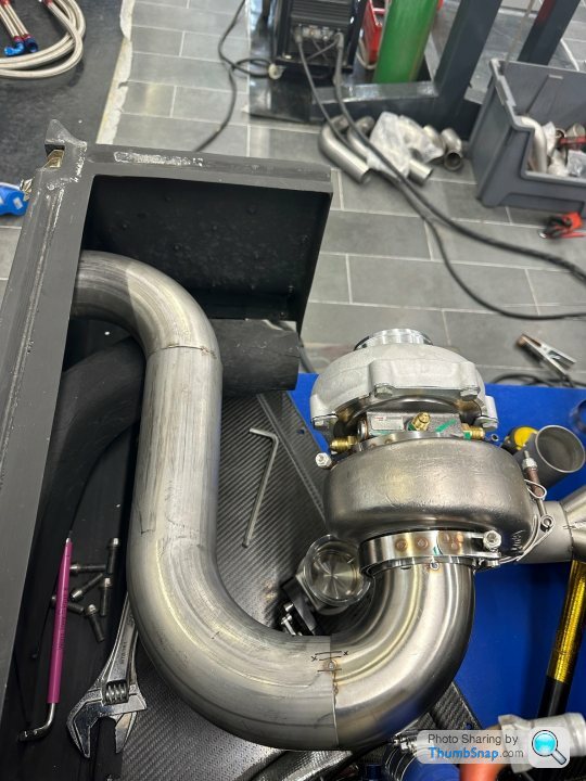
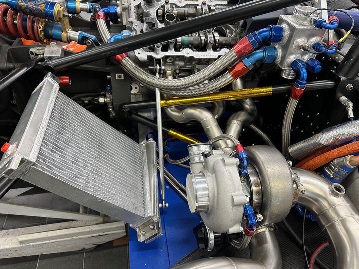
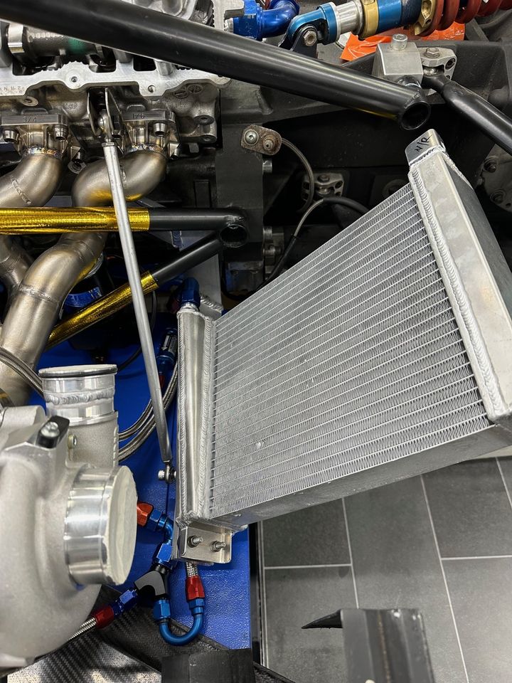
Plumbing ...
Fabricated the intercooler rad mounts, which are supported off each side of the block.
Modified the rads to add mounting points and JIC fittings.
Will use a seperate water circuit, with its own pump also mounted low down on the left side of the block.
Now to complete the hoses.
Fabricated the intercooler rad mounts, which are supported off each side of the block.
Modified the rads to add mounting points and JIC fittings.
Will use a seperate water circuit, with its own pump also mounted low down on the left side of the block.
Now to complete the hoses.
Gassing Station | General Motorsport | Top of Page | What's New | My Stuff