1st Real Project: E30 BMW 4.0 V8
Discussion


Hi all, I have been a lurker for a while and thought I would contribute with an on going build thread that I have over on E30 Zone. If its old news then I'm sorry, but if it's new to you then I hope you enjoy the read.
Basically back in late 2010 I picked up an L reg touring from a member on here (apologies if you read this, but I have forgotten your name) that had some rear axle issues.
The car was a bargain, considering the rear axle was slated to be replaced anyway, and the bodywork was in excellent condition, so a decent basis for the project. Will fire some pictures of the car at the weekend.
So, the vehicle was dragged from manchester back to birmingham and was sat there while a friend and I decided what to do to it.
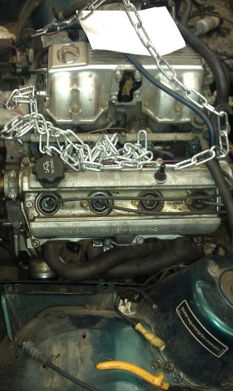
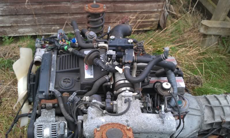
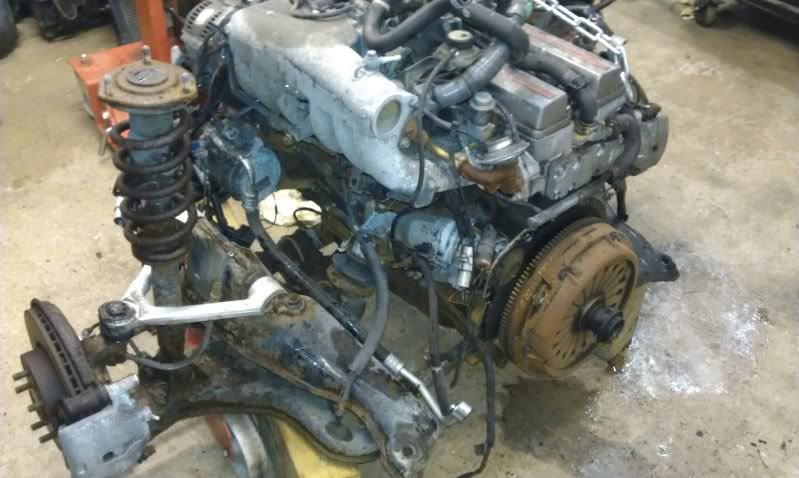
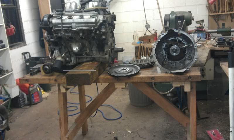
Around the same sort of time, another friend was deciding to sell his Lexus LS400 ( 4.0 V8 ) so it was purchased and the engine, gearbox, running gear, electrics, uprights, brakes etc etc were removed and thrown in to the work shop.
The engine in question: (generic image)
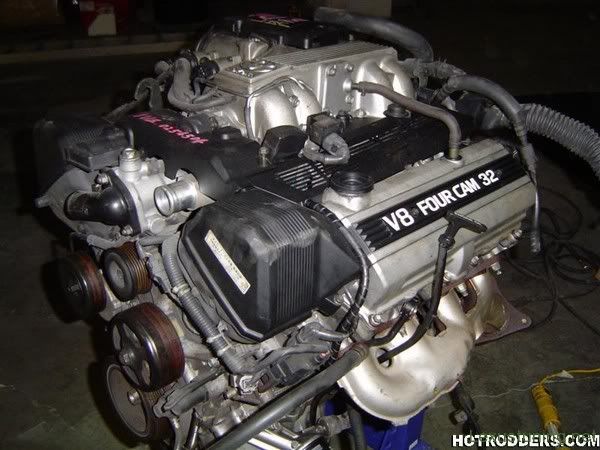
Now, the lexus V8 sounds good but only makes around 300bhp with breathing mods, which is good enough to start with but not enough for the finished article. But that can be addressed later.
The good thing is that this engine was removed from a 1991 H reg, so has the stronger bottom end. Result.
Now, this is where the 1st problem was encountered. Lexus only used this engine with an automatic transmission. No good for the track/drift car that we had in mind. But how hard can it be to bolt a manual box up?? Famous last words........
So, the transmission was removed along with the torque converter and flex plate, and sold on ebay for the princely sum of £12. Bargain.
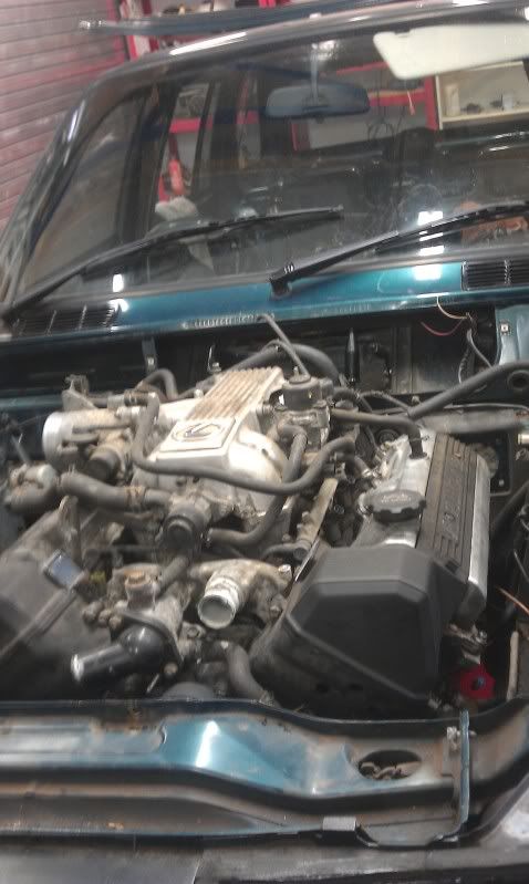
We then ripped the engine, gear box and prop out of the touring, along with the abs, brake servo and everything else that would be in the way of the V8, in preparation for dropping it in.
Would you believe, it simply slotted in with no bother at all??
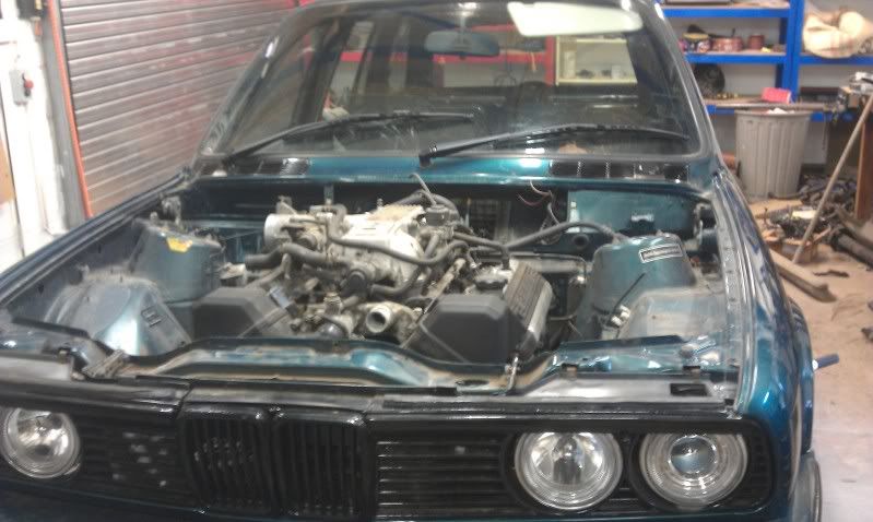
So we quickly fabbed up some mounts and ordered some "hockey puk" mounts from a land rover (£7 bargain) and the engine was in and sitting perfectly around 3 inches in front of the bulk head!
To be continued....
Basically back in late 2010 I picked up an L reg touring from a member on here (apologies if you read this, but I have forgotten your name) that had some rear axle issues.
The car was a bargain, considering the rear axle was slated to be replaced anyway, and the bodywork was in excellent condition, so a decent basis for the project. Will fire some pictures of the car at the weekend.
So, the vehicle was dragged from manchester back to birmingham and was sat there while a friend and I decided what to do to it.
Around the same sort of time, another friend was deciding to sell his Lexus LS400 ( 4.0 V8 ) so it was purchased and the engine, gearbox, running gear, electrics, uprights, brakes etc etc were removed and thrown in to the work shop.
The engine in question: (generic image)
Now, the lexus V8 sounds good but only makes around 300bhp with breathing mods, which is good enough to start with but not enough for the finished article. But that can be addressed later.
The good thing is that this engine was removed from a 1991 H reg, so has the stronger bottom end. Result.
Now, this is where the 1st problem was encountered. Lexus only used this engine with an automatic transmission. No good for the track/drift car that we had in mind. But how hard can it be to bolt a manual box up?? Famous last words........
So, the transmission was removed along with the torque converter and flex plate, and sold on ebay for the princely sum of £12. Bargain.
We then ripped the engine, gear box and prop out of the touring, along with the abs, brake servo and everything else that would be in the way of the V8, in preparation for dropping it in.
Would you believe, it simply slotted in with no bother at all??
So we quickly fabbed up some mounts and ordered some "hockey puk" mounts from a land rover (£7 bargain) and the engine was in and sitting perfectly around 3 inches in front of the bulk head!
To be continued....
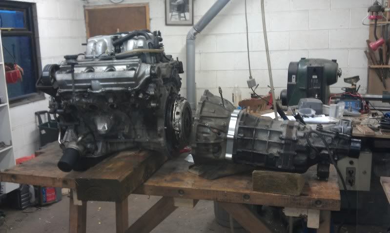
With the lump in and roughly where it needs to be, we decided to remove it and sort the gearbox issue.
After much digging we concluded that the w58 would be no where near strong enough, so we sourced an R154 from a manual supra turbo.
Big old gearbox, but mega strong and has a removable bell housing.
Prior to fitting the box, a flywheel and clutch assy was needed. A little bit of digging later and a toyota celica gt4 clutch and flywheel was mine for the basement price of £20, with a new friction plate. Mint.
Now, while the centre bore in the flywheel does sit perfectly on the V8 crank, the pcd of the bolt holes is different, 6mm IIRC. So same calls later and a billet steel flywheel with integral ring gear was on its way for £250. Yet another bargain IMO.
So, flywheel on, retained with longer ARP bolts, clutch bolted up and all was right with the world.
The bell housing was then removed from the R154 and it was offered up to the engine.
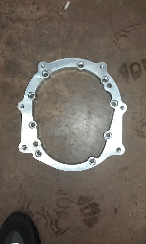
After a little more digging, I found out that a spacer plate was required to mate the R154 to the auto bell housing (thankfully retained when the auto was sold) and that a very kind chap had quickly knocked one up in CAD.
So the file was given to a friend of mine and the spacer turned up the next day, machined from a billet of 35mm ally. After some tapping, reaming and swearing, we found out that some of the CAD details were a touch wrong, but no biggie, and the plate was given a little love on the milling machine.
So bolt all of those bits together and you have this:
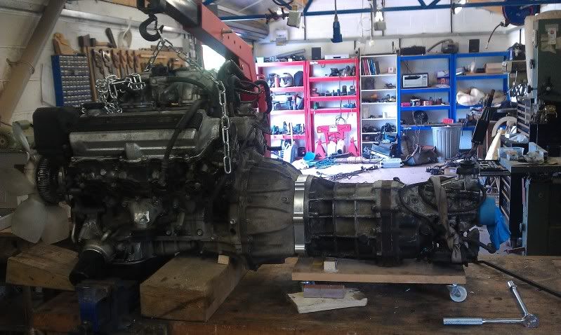
Big and heavy, but no real internal mods needed provided we ONLY want 500bhp lol.
TBC.....
After much digging we concluded that the w58 would be no where near strong enough, so we sourced an R154 from a manual supra turbo.
Big old gearbox, but mega strong and has a removable bell housing.
Prior to fitting the box, a flywheel and clutch assy was needed. A little bit of digging later and a toyota celica gt4 clutch and flywheel was mine for the basement price of £20, with a new friction plate. Mint.
Now, while the centre bore in the flywheel does sit perfectly on the V8 crank, the pcd of the bolt holes is different, 6mm IIRC. So same calls later and a billet steel flywheel with integral ring gear was on its way for £250. Yet another bargain IMO.
So, flywheel on, retained with longer ARP bolts, clutch bolted up and all was right with the world.
The bell housing was then removed from the R154 and it was offered up to the engine.
After a little more digging, I found out that a spacer plate was required to mate the R154 to the auto bell housing (thankfully retained when the auto was sold) and that a very kind chap had quickly knocked one up in CAD.
So the file was given to a friend of mine and the spacer turned up the next day, machined from a billet of 35mm ally. After some tapping, reaming and swearing, we found out that some of the CAD details were a touch wrong, but no biggie, and the plate was given a little love on the milling machine.
So bolt all of those bits together and you have this:
Big and heavy, but no real internal mods needed provided we ONLY want 500bhp lol.
TBC.....
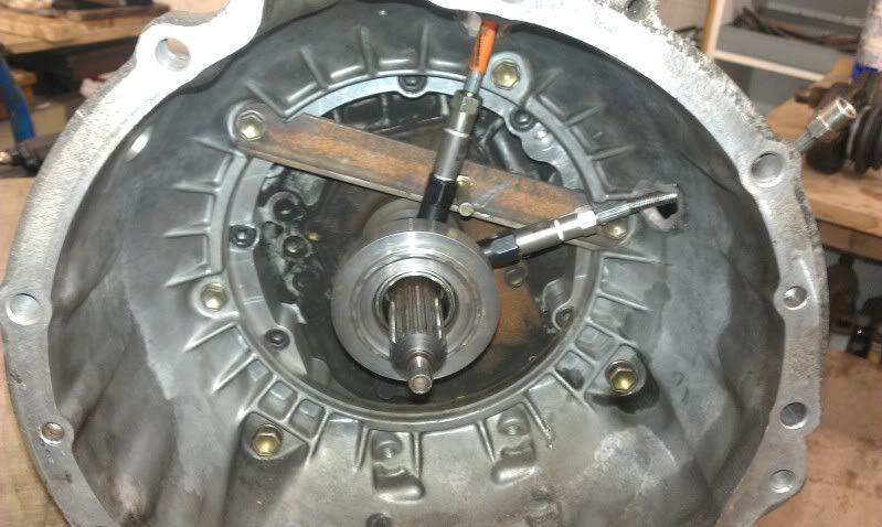
Now that the engine and box were all together, the final hurdle was how to actuate the clutch....
The standard R154 clutch system is a pull clutch with a pivot on the bell housing. Which we arent using. Plus the Celica GT4 clutch we are using is a push item.
So, a little research and one of these weee beasties was winging its way over to us from south africa:
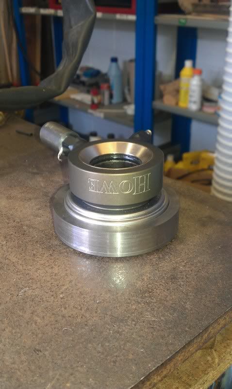
Having done the maths, and knowing that the master cylinder would give us the required throw from the slave, the only problem we needed to over come was the fact that the sleve in the gearbox wasnt really long enough once the CSC was shimmed out to where it needed to be.
Plus the bearing on the clutch cover plate side of the slave cylinder had a flat face....
So, to kill 2 birds with one stone, I quickly knocked up aspacer on the lathe that would fit over the flat faced bearing. This spacer would have a hardened bull nosed contact patch to the cover plate, so thats 1 problem fixed, plus the extra 20mm depth that this spacer added meant that the slave cylinder sat on to the gearbox input shaft sleve by a further 20mm.
Result.
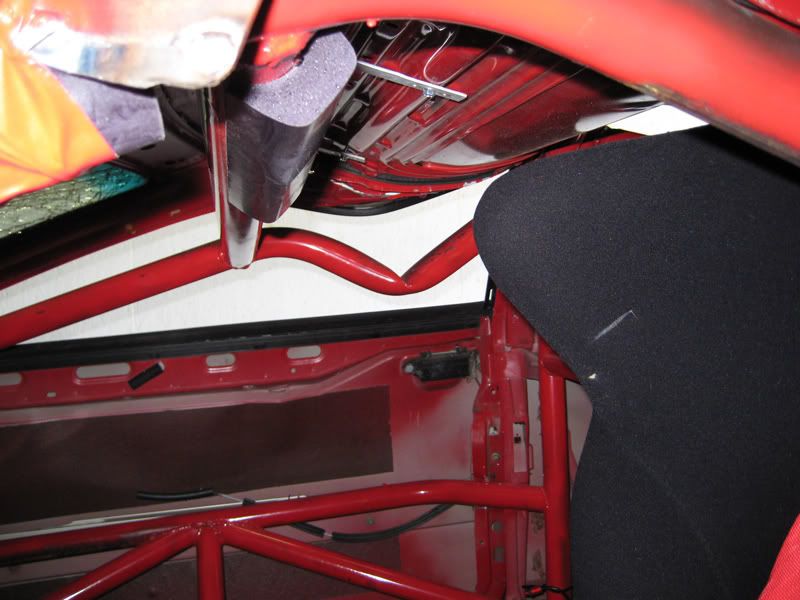
So, engine box and clutch done, time to throw it all in and see if we have a clutch pedal....
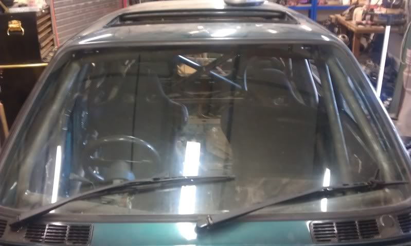
Clutch works lovely, maybe a touch heavier than I would like, but we cant have everything! PS if you look through the hole in the bulk head where the heater usually sits, you can see the gear stick :-)
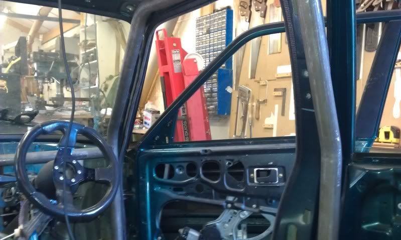
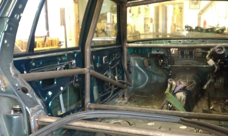
So with the engine in, attention could be turned to the small problem of manifolds, as the standard tubular units are, well crap basically. Plus they dont fit...
Here is the room we have to work with:

As you can see, the steering rack is also going to be an issue, but we will come back to that...
The standard R154 clutch system is a pull clutch with a pivot on the bell housing. Which we arent using. Plus the Celica GT4 clutch we are using is a push item.
So, a little research and one of these weee beasties was winging its way over to us from south africa:
Having done the maths, and knowing that the master cylinder would give us the required throw from the slave, the only problem we needed to over come was the fact that the sleve in the gearbox wasnt really long enough once the CSC was shimmed out to where it needed to be.
Plus the bearing on the clutch cover plate side of the slave cylinder had a flat face....
So, to kill 2 birds with one stone, I quickly knocked up aspacer on the lathe that would fit over the flat faced bearing. This spacer would have a hardened bull nosed contact patch to the cover plate, so thats 1 problem fixed, plus the extra 20mm depth that this spacer added meant that the slave cylinder sat on to the gearbox input shaft sleve by a further 20mm.
Result.
So, engine box and clutch done, time to throw it all in and see if we have a clutch pedal....
Clutch works lovely, maybe a touch heavier than I would like, but we cant have everything! PS if you look through the hole in the bulk head where the heater usually sits, you can see the gear stick :-)
So with the engine in, attention could be turned to the small problem of manifolds, as the standard tubular units are, well crap basically. Plus they dont fit...
Here is the room we have to work with:
As you can see, the steering rack is also going to be an issue, but we will come back to that...
Right, after taking a bit of a look at manifolds, and sorting the passenger side out, shown below, this was shelved, as the ECU and CDS tubing for the cage arrived.
The ECU in question is a Megasquirt 2.2, of which I have no experience, and its a solder it together yourself job! That is about where we are with the project so far.
To do:
Solder ecu together and make wiring loom/map the thing
Make decent pipe bender
Use decent pipe bender to make cage (ambitious)
Sort fuel system
Sort brake system (sourced remote servos)
Move steering rack
Sort cooling system
Change rear dif for massive lexus one (and shafts)
Finish prop
Do interior
Drive like a lunatic
I shall update when there is progress, but as I mentioned, ECU soldering is all I shall be doing for a while and I can only work on the thing on sundays.
After seeing the price of a decent cage, we decided to order some CDS and have a go at making our own. Brave I know, but if you dont try then you never know.
The tube spec is a little ott, but safety 1st. OD 41mm ( 1" & 5/8 ) with a wall thickness of 3.3mm
Purchased a clarke pipe bender (a mistake) which included various dies, one of which wasnt too dissimilar to the OD of the tube in question.
1st attempt, tube kinked badly. Which was half expected.
2nd attempt, tube filled with kiln dried sand and compacted, with both tube ends sealed up. This started off very promising, but when we got to roughly 20degrees, the tube burst! Spraying sand everywhere I might add. Unexpected.
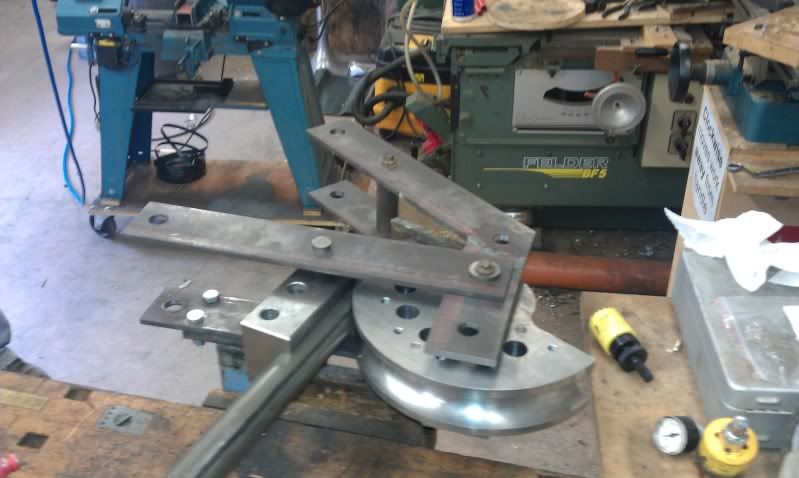
So, the clarke job was thrown away and some plans knocked up to make a decent tube former, which would have a static die and a rotating die that would "form" the bend and should prevent kinking etc.
With that in mind, I quickly knocked up a couple of dies in CAD and emailed them to a friend. The next day, this turned up:
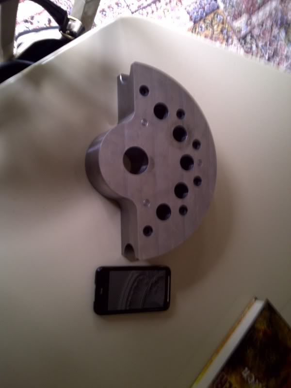
Shown next to my htc desire HD for size comparison. Basically its massive lol
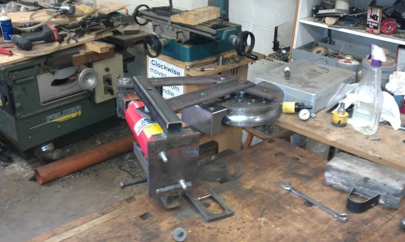
The next step was to quickly knock up a frame to mount it in, which would also act as the forming guide. A little cutting drilling and welding later and we have the almost finished article:
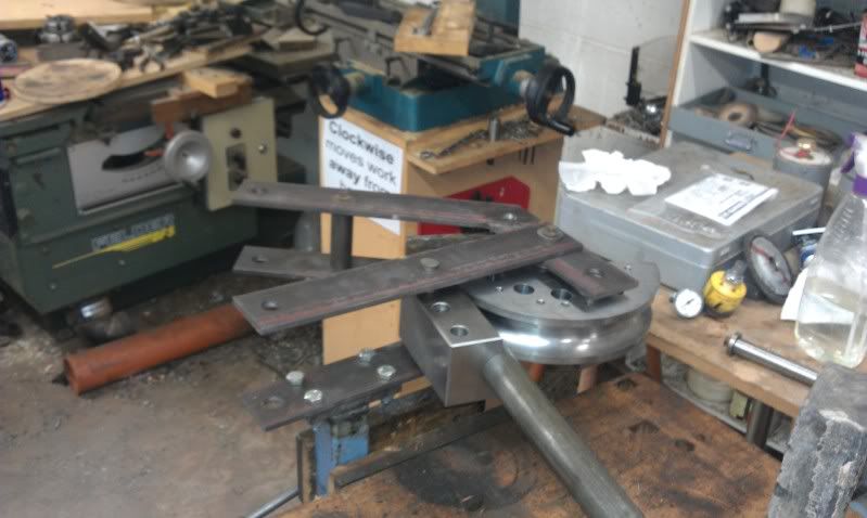
Originally we had thought to make a cam and a handle which we could hand crank, however the thickness of the tube and the effort involved led to a quick rethink....
The bottle jack from the original clarke (s te) pipe bender was fitted in to a cradle and to the former, and it was time to try another bend....
Lo and behold:
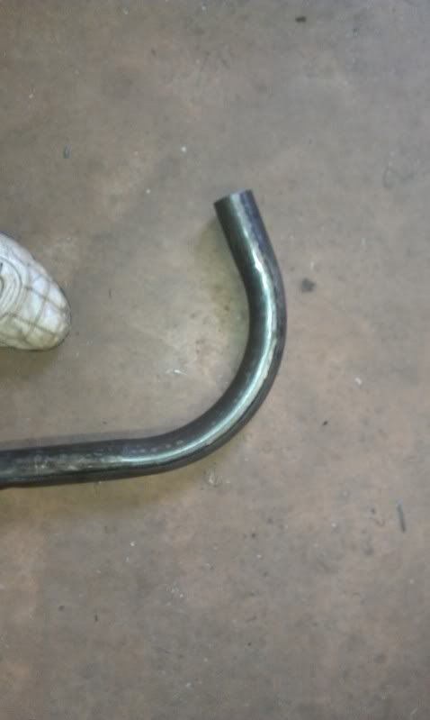
An awesome result in my opinion.
So, we crack on with the cage on sunday. Fingers crossed...
The ECU in question is a Megasquirt 2.2, of which I have no experience, and its a solder it together yourself job! That is about where we are with the project so far.
To do:
Solder ecu together and make wiring loom/map the thing
Make decent pipe bender
Use decent pipe bender to make cage (ambitious)
Sort fuel system
Sort brake system (sourced remote servos)
Move steering rack
Sort cooling system
Change rear dif for massive lexus one (and shafts)
Finish prop
Do interior
Drive like a lunatic
I shall update when there is progress, but as I mentioned, ECU soldering is all I shall be doing for a while and I can only work on the thing on sundays.
After seeing the price of a decent cage, we decided to order some CDS and have a go at making our own. Brave I know, but if you dont try then you never know.
The tube spec is a little ott, but safety 1st. OD 41mm ( 1" & 5/8 ) with a wall thickness of 3.3mm
Purchased a clarke pipe bender (a mistake) which included various dies, one of which wasnt too dissimilar to the OD of the tube in question.
1st attempt, tube kinked badly. Which was half expected.
2nd attempt, tube filled with kiln dried sand and compacted, with both tube ends sealed up. This started off very promising, but when we got to roughly 20degrees, the tube burst! Spraying sand everywhere I might add. Unexpected.
So, the clarke job was thrown away and some plans knocked up to make a decent tube former, which would have a static die and a rotating die that would "form" the bend and should prevent kinking etc.
With that in mind, I quickly knocked up a couple of dies in CAD and emailed them to a friend. The next day, this turned up:
Shown next to my htc desire HD for size comparison. Basically its massive lol
The next step was to quickly knock up a frame to mount it in, which would also act as the forming guide. A little cutting drilling and welding later and we have the almost finished article:
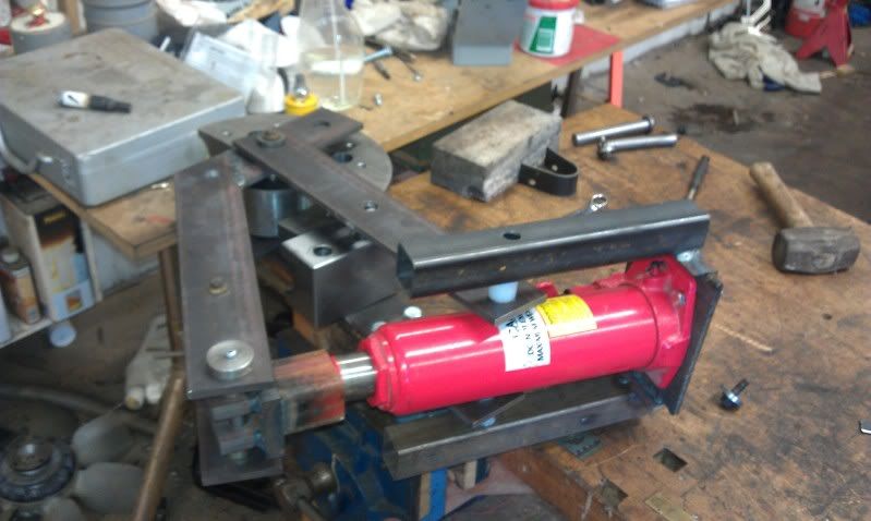
Originally we had thought to make a cam and a handle which we could hand crank, however the thickness of the tube and the effort involved led to a quick rethink....
The bottle jack from the original clarke (s
te) pipe bender was fitted in to a cradle and to the former, and it was time to try another bend....Lo and behold:
An awesome result in my opinion.
So, we crack on with the cage on sunday. Fingers crossed...
Right, well after an early start on Sunday, a decent days work was put in.
Firstly finalised the bottle jack instal on the pipe bender:
Then got to work making the cage....
Fairly self explanatory really:
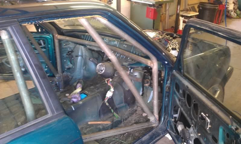
After the roll hoop, the tubes that run up the a pillar were bent up and tacked in place
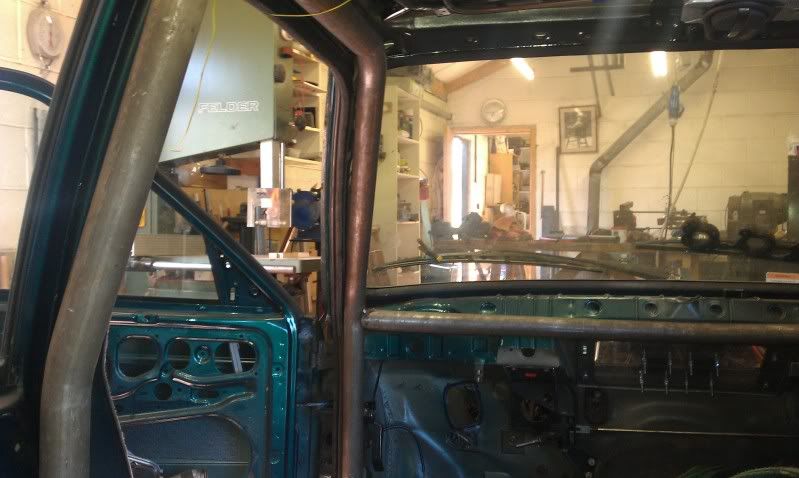
Then a cross piece was bent to triangulate the 2 a pillar tubes to the bulk head, cant really see in the above picture but the horizontal bar is bent towards the bay....
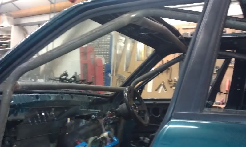
Then bent up a piece to run along the top of the screen which is to be welded to the inner roof skin.
The reason everything looks on the piss in the last pic is that I have cut 2 holes in the floor and dropped the roll hoop through, to allow me access to weld around the whole of the tube intersections.
More at the weekend I hope.
Firstly finalised the bottle jack instal on the pipe bender:
Then got to work making the cage....
Fairly self explanatory really:
After the roll hoop, the tubes that run up the a pillar were bent up and tacked in place
Then a cross piece was bent to triangulate the 2 a pillar tubes to the bulk head, cant really see in the above picture but the horizontal bar is bent towards the bay....
Then bent up a piece to run along the top of the screen which is to be welded to the inner roof skin.
The reason everything looks on the piss in the last pic is that I have cut 2 holes in the floor and dropped the roll hoop through, to allow me access to weld around the whole of the tube intersections.
More at the weekend I hope.
Some more action last week, I started off by having to do a repair to one of my dads golf clubs lol, the tool had snapped the carbon shaft!
So I turned a tapered insert, bonded it in with 3M 9323 adhesive, sanded it down, and wrapped the whole shabang in prepreg UD carbon.
Here it is prior to going in to tha clave at work:
So with that all sorted (ended up mint by the by, and mega strong!) it was back to the cage fabrication.
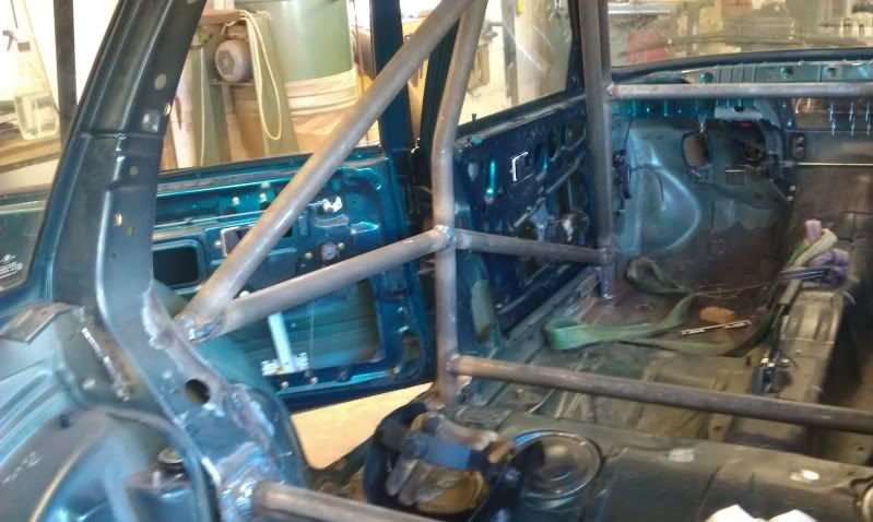
Rear door members tacked in car line to transfer forces from a head on (god forbid) along with front door bars which are somewhat of a compramise due to having to get my fat ass in and out of the car!
Additionally the bars going across the car at the bottom of the roll hoop and between the rear turrets have been tacked in place.
Next we moved on to the plating of the rear turrets to give a solid mount for some triangulation.

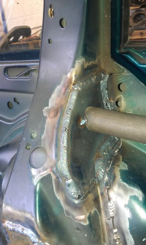
May have gone a bit OTT with the welding in the close up lol but you can never be too sure....
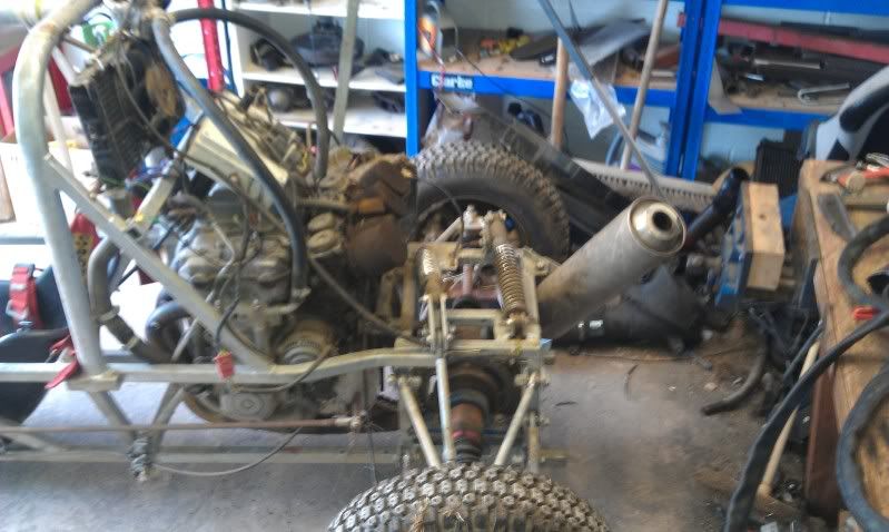
And then as luck would have it, the gas ran out for the MIG. Tried to continue using the TIG, but it was a huge pain in the arse, so decided to get the "kart" out and spend the rest of the day acting like a hooligan in the fields lol
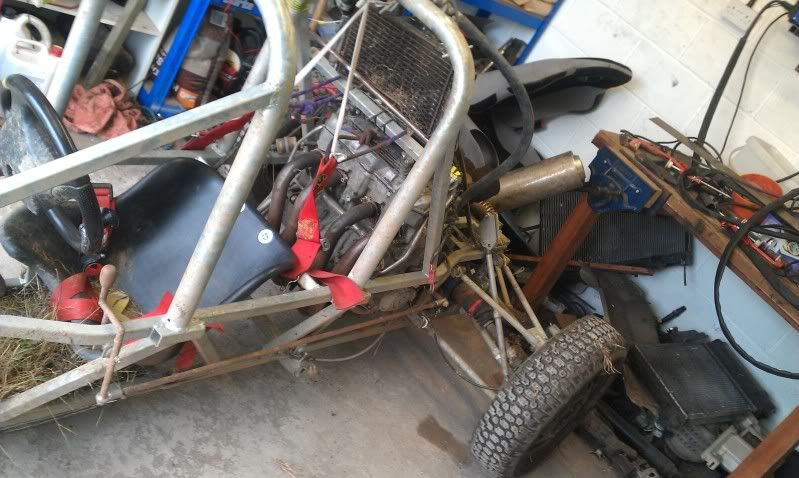
Its quite entertaining if the weather is ok, as the power to weight is quite high!
Well thats all for now, more after the weekend no doubt.
So I turned a tapered insert, bonded it in with 3M 9323 adhesive, sanded it down, and wrapped the whole shabang in prepreg UD carbon.
Here it is prior to going in to tha clave at work:
So with that all sorted (ended up mint by the by, and mega strong!) it was back to the cage fabrication.
Rear door members tacked in car line to transfer forces from a head on (god forbid) along with front door bars which are somewhat of a compramise due to having to get my fat ass in and out of the car!
Additionally the bars going across the car at the bottom of the roll hoop and between the rear turrets have been tacked in place.
Next we moved on to the plating of the rear turrets to give a solid mount for some triangulation.
May have gone a bit OTT with the welding in the close up lol but you can never be too sure....
And then as luck would have it, the gas ran out for the MIG. Tried to continue using the TIG, but it was a huge pain in the arse, so decided to get the "kart" out and spend the rest of the day acting like a hooligan in the fields lol
Its quite entertaining if the weather is ok, as the power to weight is quite high!
Well thats all for now, more after the weekend no doubt.
Right, spent 6 bloody hours on the motorway saturday doing a total of 120 miles! Traffic sucks balls.
The end result of this nightmare is a pair of lightweight bucket seats that we needed prior to finishing the cage, just to make sure we didnt encroach on the driving position too much.
So on sunday with a new cylinder of welding gas, we cracked on with the cage:
The nearly vertical members in the above picture are to prevent the cage collapsing in circumstances like this poor guy experienced:
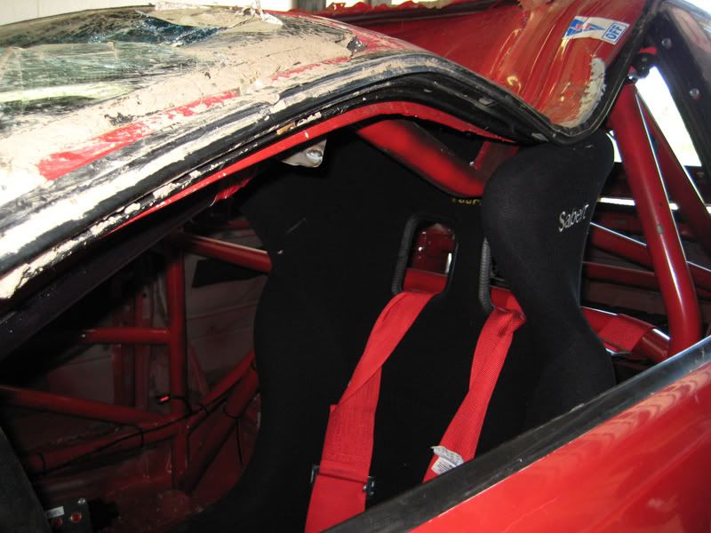
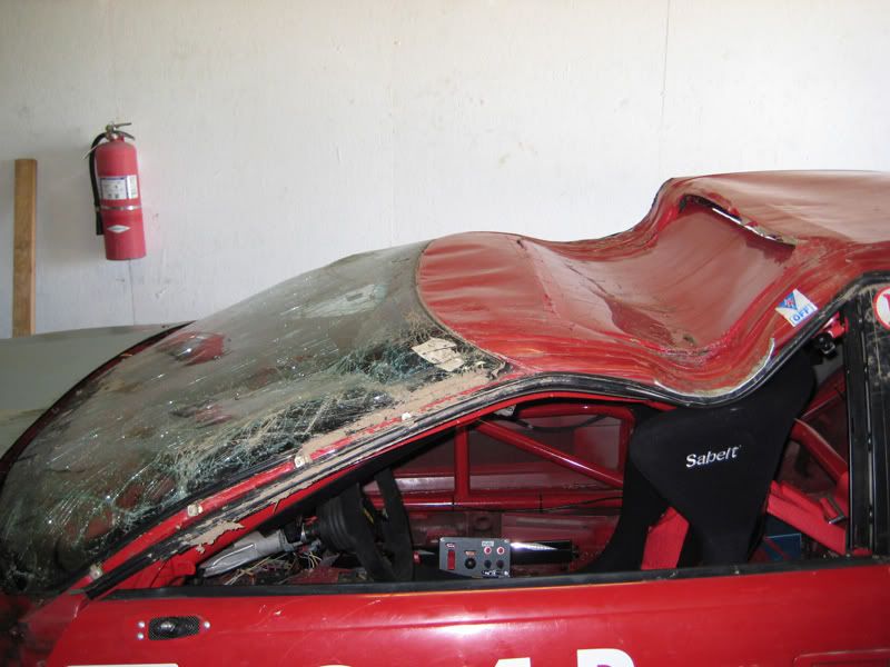
A freak accident with wierd circumstances, but I dont fancy the cage crushing my helmet, so the extra bracing went in! For those interested, the thread covering the destruction of the above audi is here: http://www.motorgeek.com/viewtopic.php?f=6&t=1...
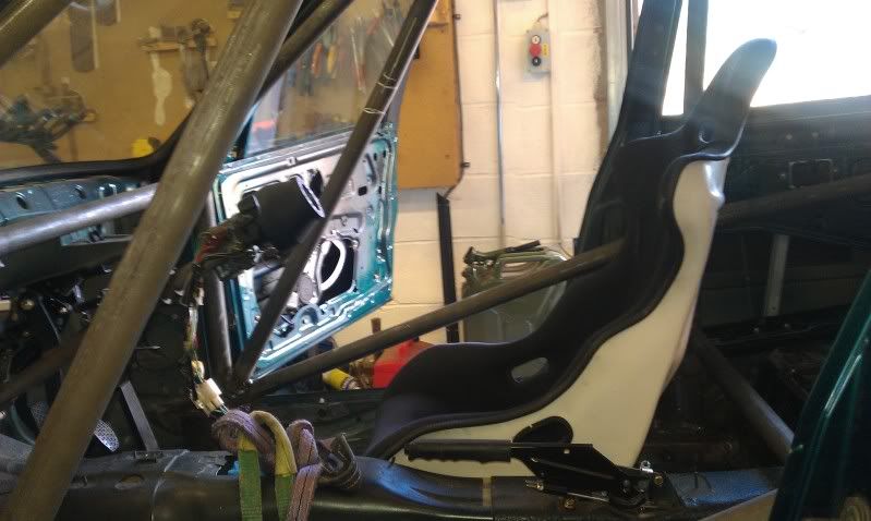
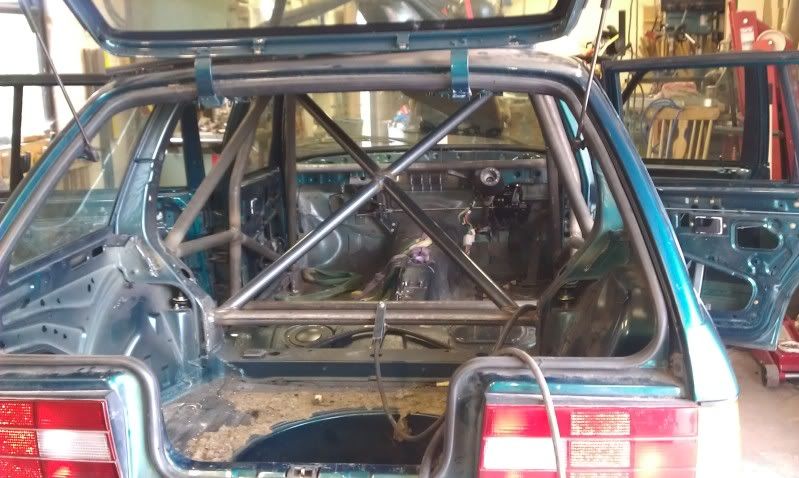
With the front all braced and a seat thrown in so we could make sure that we can get in/out (just) we moved on to the rear section of the cage, and the bracing for the roll hoop:

And then the cross bracing to add torsional stiffness:

With that all welded up, we decided to do a quick stiffness test. Prior to fitting the cage, we mounted a laser level on the front corner of the car, pointing at a target mounted on the opposite rear corner.
We marked the point at which the pointer was hitting the target, then we jacked the front corner of the car up so that both near side wheels were off the floor and the car was in torsion.
We then marked the changed position of the point, and measured the difference:

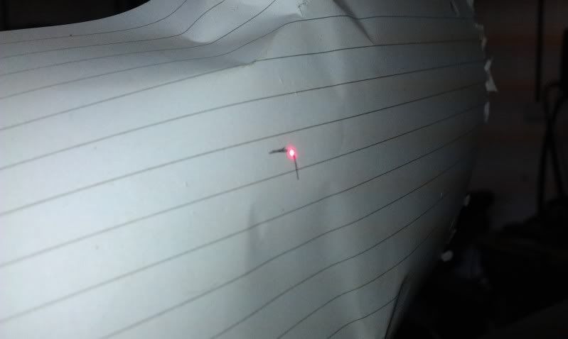
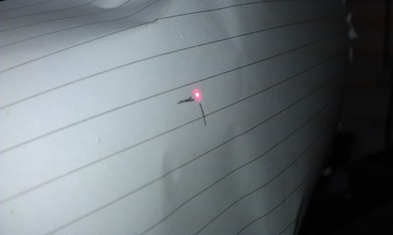
We did this again with the finished cage all welded up, and with the exact same test, the difference in position of the laser pointer was less than 1/3rd. Stiff is good!
After all this messing around and the subsequent back patting, it was getting pretty late on, so we decided to just do a quick job to finish off.
As you may be able to tell from the pictures of the engine bay, getting the master cylinder to fit is going to be a nightmare, so we decided to mount the master cylinder, without servo unit, in the passenger footwell, with the intention of running 2 remote servo's in the boot.
With this firmly in mind, we hacked up the mounting bracket, modified some bell cranks and ended up with this:
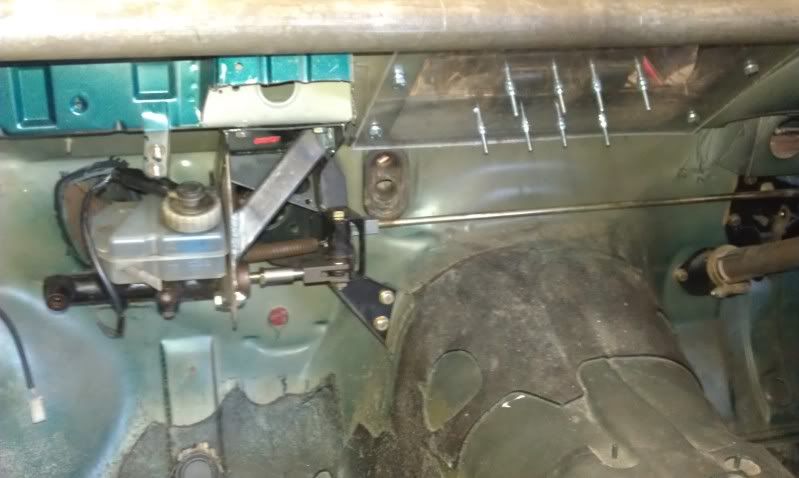
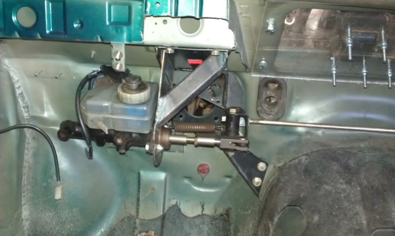
The horizontal bar running along the bulkhead is the standard BMW jobby, which takes the pedal movement and transfers it to a bell crank that changes it to movement in car line, through the bulk head. Whereas our modified version keeps the movement across the car and our bell crank simply reverses its direction. It was simply a matter of then bracing the master cylinder to resist forces in the appropriate direction.
Works a treat. More next weekend.
The end result of this nightmare is a pair of lightweight bucket seats that we needed prior to finishing the cage, just to make sure we didnt encroach on the driving position too much.
So on sunday with a new cylinder of welding gas, we cracked on with the cage:
The nearly vertical members in the above picture are to prevent the cage collapsing in circumstances like this poor guy experienced:
A freak accident with wierd circumstances, but I dont fancy the cage crushing my helmet, so the extra bracing went in! For those interested, the thread covering the destruction of the above audi is here: http://www.motorgeek.com/viewtopic.php?f=6&t=1...
With the front all braced and a seat thrown in so we could make sure that we can get in/out (just) we moved on to the rear section of the cage, and the bracing for the roll hoop:
And then the cross bracing to add torsional stiffness:
With that all welded up, we decided to do a quick stiffness test. Prior to fitting the cage, we mounted a laser level on the front corner of the car, pointing at a target mounted on the opposite rear corner.
We marked the point at which the pointer was hitting the target, then we jacked the front corner of the car up so that both near side wheels were off the floor and the car was in torsion.
We then marked the changed position of the point, and measured the difference:
We did this again with the finished cage all welded up, and with the exact same test, the difference in position of the laser pointer was less than 1/3rd. Stiff is good!
After all this messing around and the subsequent back patting, it was getting pretty late on, so we decided to just do a quick job to finish off.
As you may be able to tell from the pictures of the engine bay, getting the master cylinder to fit is going to be a nightmare, so we decided to mount the master cylinder, without servo unit, in the passenger footwell, with the intention of running 2 remote servo's in the boot.
With this firmly in mind, we hacked up the mounting bracket, modified some bell cranks and ended up with this:
The horizontal bar running along the bulkhead is the standard BMW jobby, which takes the pedal movement and transfers it to a bell crank that changes it to movement in car line, through the bulk head. Whereas our modified version keeps the movement across the car and our bell crank simply reverses its direction. It was simply a matter of then bracing the master cylinder to resist forces in the appropriate direction.
Works a treat. More next weekend.
Not a lot done this weekend as we are waiting for delivery of some bits.
Finished off the mounting of the drivers and passenger seats:
This was a time consuming job, with a lot of in and outing of both seats and tacking/cutting and retacking of brackets etc. Happy with the finished result though!
Next moved on to the harness mouning points, welding some strengthening plates to which the eyelets need to be mounted etc. No pics really, as its straight forward chod.
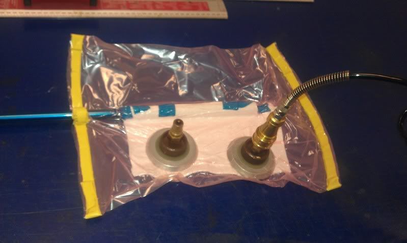
To finish off I had to turn some fittings for my vacuum pump set up, so I can crack on with some carbon work ive been asked to do, so my partner in crime decided to make us a gearnob lol.
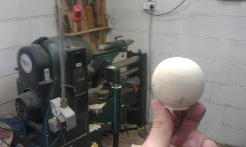
He located a decent block of holly from the wood shed (scheduled to be burnt to keep us warm in the winter!) and proceeded to make a large amount of wood shavings on the wood turning lathe lol.

Which resulted in this:
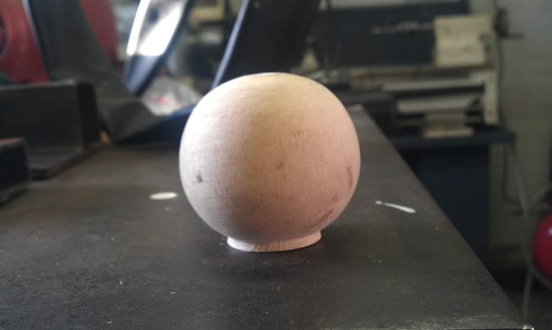
A bit of TLC and it will do nicely I think! Plus its very light
Anyway, on to more exciting things at the weekened (I hope)
Finished off the mounting of the drivers and passenger seats:
This was a time consuming job, with a lot of in and outing of both seats and tacking/cutting and retacking of brackets etc. Happy with the finished result though!
Next moved on to the harness mouning points, welding some strengthening plates to which the eyelets need to be mounted etc. No pics really, as its straight forward chod.
To finish off I had to turn some fittings for my vacuum pump set up, so I can crack on with some carbon work ive been asked to do, so my partner in crime decided to make us a gearnob lol.
He located a decent block of holly from the wood shed (scheduled to be burnt to keep us warm in the winter!) and proceeded to make a large amount of wood shavings on the wood turning lathe lol.
Which resulted in this:
A bit of TLC and it will do nicely I think! Plus its very light
Anyway, on to more exciting things at the weekened (I hope)
Not really had much chance to do anything this weekend, so not a great deal to say!
Knocked up some exhaust manifold flanges in CAD and had them laser cut from 316 stainless:
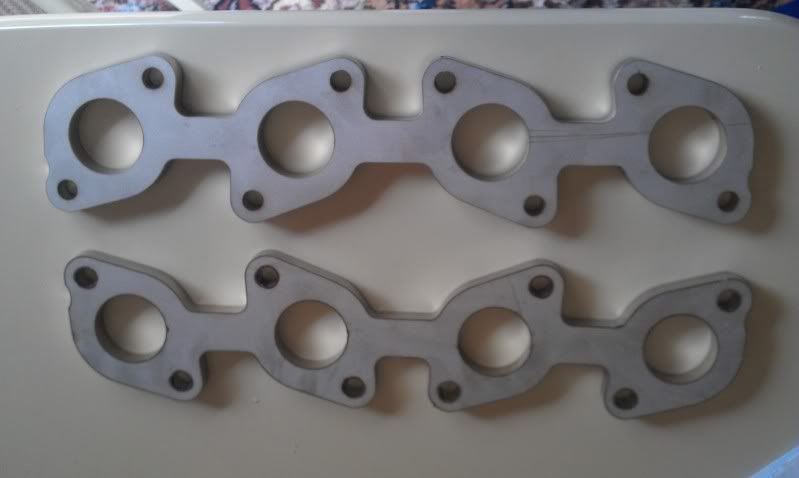
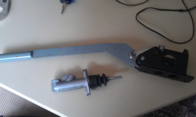
Bought a hydro hand brake for the bargain sum of £60, just needs a little TLC:
Hopefully will get a call to say that my schedule 40 316 stainless bends are ready in the next day or so, and will crack on with the exhaust at the weekend.
Knocked up some exhaust manifold flanges in CAD and had them laser cut from 316 stainless:
Bought a hydro hand brake for the bargain sum of £60, just needs a little TLC:
Hopefully will get a call to say that my schedule 40 316 stainless bends are ready in the next day or so, and will crack on with the exhaust at the weekend.
Right, no sign of the bends so the manifolds have been put on hold for now, although there is still more than enough work to be done...
We started off by soldering the ecu together. We started with this (image shamelessly stolen from the interweb as I didnt take a picture prior to starting the soldering):

and ended up with this (ECU):

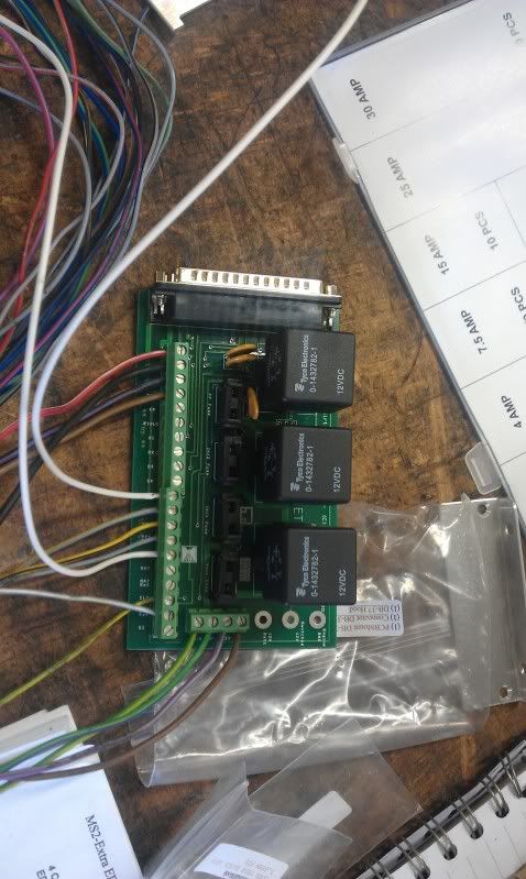
and this (Relay Board):
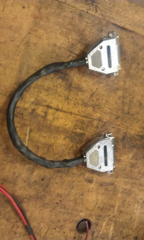
Then we had to make and solder up a cable which would link the ecu to the relay/power board, which ended up looking like this:
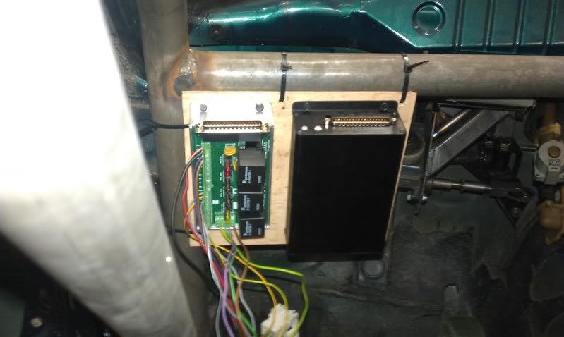
With that all done, we mounted the boards in the car just temporarily so that we can test everything when its all wired up:
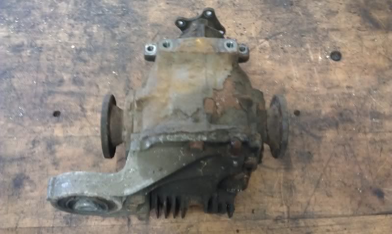
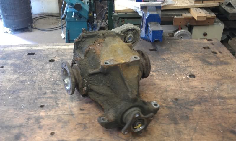
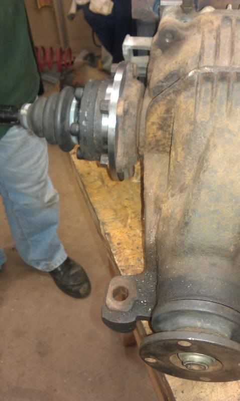
Then, once we had grown bored of soldering, we decided to remove the rear diff, as it was grumbling and probably wouldnt like V8 power anyway.
So after much swearing and hitting of things with hammers, we ended up with a diff on the bench:
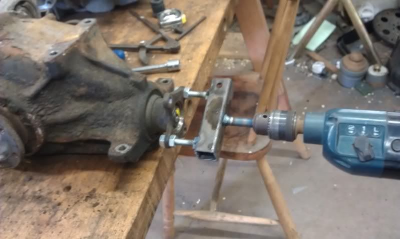
And just to confirm that it was the cause of the grumble, we quickly knocked up a test jig:
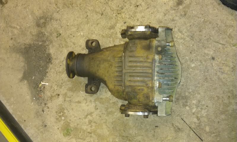
Thankfully it was the source of the problem and is in laymans terms FUBAR. But not to worry, as we have some potential replacements, shown here:

At the far end we have the standard 318 touring diff (boooo)
In the middle we have the diff from an LS400, massive (38kg) and no doubt capable of taking the horses, but appears to be a simple open diff (boooo)
The closest diff however seems to be the best choice. It is from a mk3 supra turbo, which coincidentally is the source of the gearbox we are using, and is an LSD. It is equally massive compared to the LS400 diff and just as heavy, but looks like it will fit quite easily and will no doubt take the power.
With a little bit of love, the diff now sits in the rear subframe nice and snug, so more pictures to come after the weekend.
We started off by soldering the ecu together. We started with this (image shamelessly stolen from the interweb as I didnt take a picture prior to starting the soldering):
and ended up with this (ECU):
and this (Relay Board):
Then we had to make and solder up a cable which would link the ecu to the relay/power board, which ended up looking like this:
With that all done, we mounted the boards in the car just temporarily so that we can test everything when its all wired up:
Then, once we had grown bored of soldering, we decided to remove the rear diff, as it was grumbling and probably wouldnt like V8 power anyway.
So after much swearing and hitting of things with hammers, we ended up with a diff on the bench:
And just to confirm that it was the cause of the grumble, we quickly knocked up a test jig:
Thankfully it was the source of the problem and is in laymans terms FUBAR. But not to worry, as we have some potential replacements, shown here:
At the far end we have the standard 318 touring diff (boooo)
In the middle we have the diff from an LS400, massive (38kg) and no doubt capable of taking the horses, but appears to be a simple open diff (boooo)
The closest diff however seems to be the best choice. It is from a mk3 supra turbo, which coincidentally is the source of the gearbox we are using, and is an LSD. It is equally massive compared to the LS400 diff and just as heavy, but looks like it will fit quite easily and will no doubt take the power.
With a little bit of love, the diff now sits in the rear subframe nice and snug, so more pictures to come after the weekend.
Right, after a little break due to work commitments, we decided to throw some fuel in the thing and see if starts!
Bear in mind that its just a thrown together loom, dodgy map, no lambda sensor or headers, so its a bit of a lash up.
1st attempt:
http://smg.photobucket.com/albums/v649/b3rk/?actio...
Hopefully prop and drive shafts sorted after next weekend, then its a load of tidying up!
Bear in mind that its just a thrown together loom, dodgy map, no lambda sensor or headers, so its a bit of a lash up.
1st attempt:
http://smg.photobucket.com/albums/v649/b3rk/?actio...
Hopefully prop and drive shafts sorted after next weekend, then its a load of tidying up!
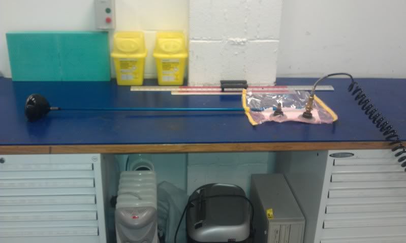
Picked up the prop today, quite a chunky affair, given that its 1440mm in overall length and will have to live with shaft speeds potentially over 9k RPM.....
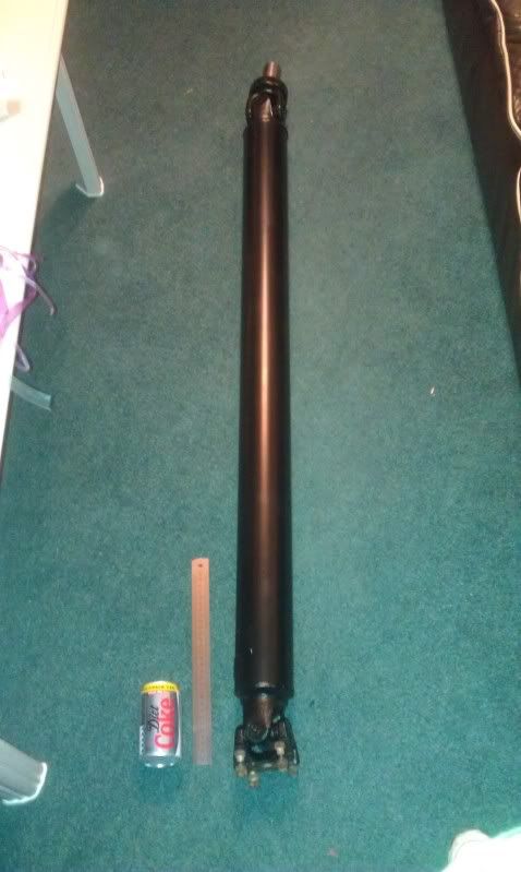
Pictured next to a coke can and 300mm steel rule for size comparison.
Not had chance to stick it on the scales yet, but I would say its roughly 6kg, which is a big saving over the standard supra prop, which weighed in at 16kg! Albeit with a bearing in the centre....
Pictured next to a coke can and 300mm steel rule for size comparison.
Not had chance to stick it on the scales yet, but I would say its roughly 6kg, which is a big saving over the standard supra prop, which weighed in at 16kg! Albeit with a bearing in the centre....
Right, another day on the car today.
The focus was on getting the wheels turning, so with that in mind some GCSE maths was in order lol
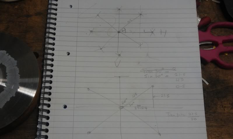
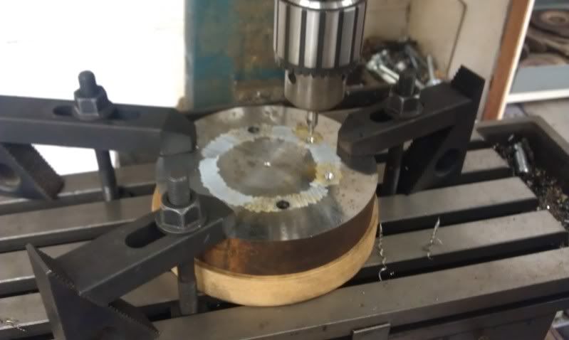
Which allowed us to mark this billet.........
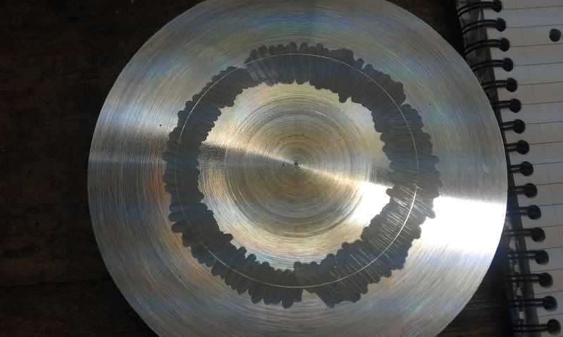
with the co-ordinates for all of the holes required to make a drive shaft adaptor. Obviously Toyota Supra to BMW E30.
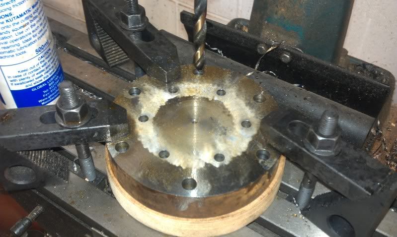
It would have been much easier with a rotary table, much faster too!
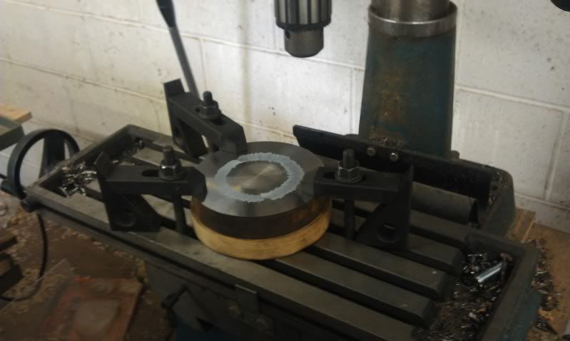
Then it was on to the lathe for some turning to make the profiles.
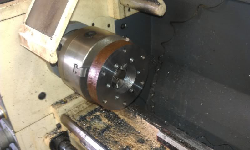
A before and after shot.......
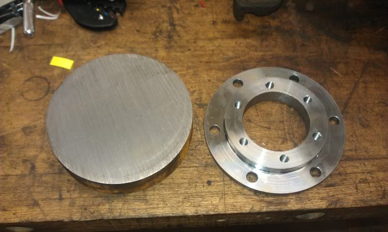
Then it was time to offer the spacer and shaft up to the diff, to see how much of a cock up we had made lol
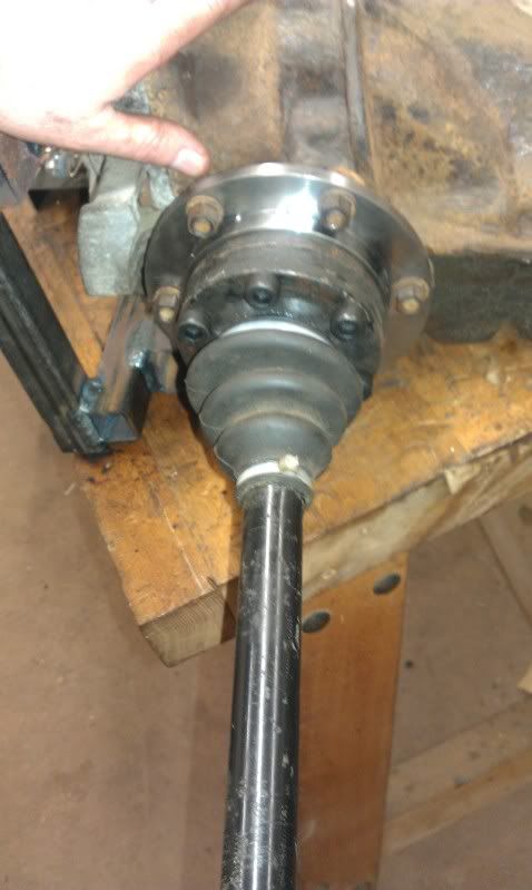
But lo and behold, it could have been made for the job!!
By this time it was getting on a bit, but we managed to fit the diff and prop, to find that clearance past the petrol tank for a 3.5" prop shaft, is a little sparse!
Next week it will all have to come back out for some mods so that it all clears. Oh well, not to worry!
The focus was on getting the wheels turning, so with that in mind some GCSE maths was in order lol
Which allowed us to mark this billet.........
with the co-ordinates for all of the holes required to make a drive shaft adaptor. Obviously Toyota Supra to BMW E30.
It would have been much easier with a rotary table, much faster too!
Then it was on to the lathe for some turning to make the profiles.
A before and after shot.......
Then it was time to offer the spacer and shaft up to the diff, to see how much of a cock up we had made lol
But lo and behold, it could have been made for the job!!
By this time it was getting on a bit, but we managed to fit the diff and prop, to find that clearance past the petrol tank for a 3.5" prop shaft, is a little sparse!
Next week it will all have to come back out for some mods so that it all clears. Oh well, not to worry!
Not a great deal of progress today, it was mainly modifying the petrol tank and trans tunnel to take the larger diameter prop shaft without fouling.
However, I found out that david had made a useful gadget for his other half, to help with making pasta of all things!
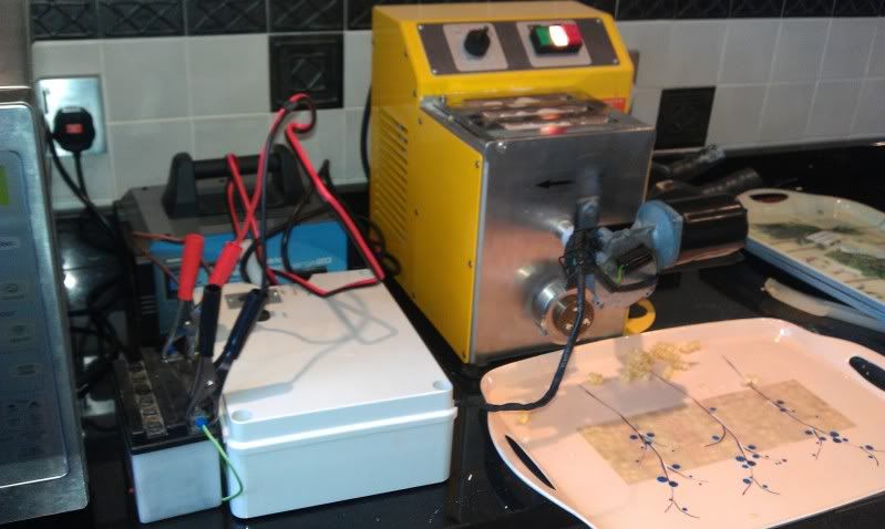
Yes, that is a window wiper motor, the intermitent control system, a motorcycle battery and a cut down steel rule....
http://smg.photobucket.com/albums/v649/b3rk/?actio...
Much better than having to stand there and cut the pasta by hand! Superb use of spares too.
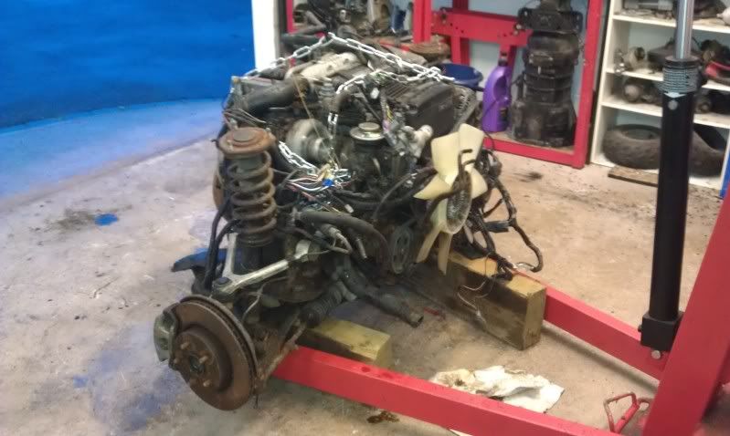
Anyway, after the tunnel mods, it was on to splitting our spare gearbox from the donor engine, which is on ebay as we speak lol, so that its all ready for collection.
Started off like this...........
Took some man handling to get it in to the workshop.....
Now looks like this......
Leaving us with this!.....
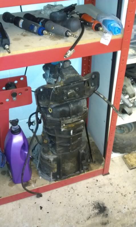
Anyway, next weekend will hopefully see the drive train all done, and on to something a little more exciting. I hope.
However, I found out that david had made a useful gadget for his other half, to help with making pasta of all things!
Yes, that is a window wiper motor, the intermitent control system, a motorcycle battery and a cut down steel rule....
http://smg.photobucket.com/albums/v649/b3rk/?actio...
Much better than having to stand there and cut the pasta by hand! Superb use of spares too.
Anyway, after the tunnel mods, it was on to splitting our spare gearbox from the donor engine, which is on ebay as we speak lol, so that its all ready for collection.
Started off like this...........
Took some man handling to get it in to the workshop.....
Now looks like this......
Leaving us with this!.....
Anyway, next weekend will hopefully see the drive train all done, and on to something a little more exciting. I hope.
Right, after last weeks' lack of real progress, this week has been much more fruitful.
Continued with the drive train first, and after making clearance for the massive prop, moved on to the 2nd driveshaft adaptor. Leaving the diff looking like this......
We then fitted the driveshafts and dropped the car, to find that the passenger side drive shaft was now too long.
After some re-measuring to ensure that a mistake had not been made, it turns out that our assumption that the standard shafts were different lengths (to account for the offset diff) was in error. So standard shafts being equal length means that one side fits lovely with the spacer, and the other is too long by roughly 20mm.
So on to some drive shaft mods..........

Which sorted the problem and means that the car now moves under its own power! Woohoo!
So, with all that sorted, we stripped the car (again) so that the final brackets etc could be sent for galvanizing. Additionally it gives me chance to take and post some pics that were missing from the early part of the build.....
Bay looking empty:

Engine and box just split:
Bit of a close up of the CSC and its modded bearing face:
and finally the spacer plate that joins the R154 to 1UZ auto bell housing:
Next week we should start working on either the cooling system, brake system or exhaust system, depending on which parts arrive 1st!
Continued with the drive train first, and after making clearance for the massive prop, moved on to the 2nd driveshaft adaptor. Leaving the diff looking like this......
We then fitted the driveshafts and dropped the car, to find that the passenger side drive shaft was now too long.
After some re-measuring to ensure that a mistake had not been made, it turns out that our assumption that the standard shafts were different lengths (to account for the offset diff) was in error. So standard shafts being equal length means that one side fits lovely with the spacer, and the other is too long by roughly 20mm.
So on to some drive shaft mods..........
Which sorted the problem and means that the car now moves under its own power! Woohoo!
So, with all that sorted, we stripped the car (again) so that the final brackets etc could be sent for galvanizing. Additionally it gives me chance to take and post some pics that were missing from the early part of the build.....
Bay looking empty:
Engine and box just split:
Bit of a close up of the CSC and its modded bearing face:
and finally the spacer plate that joins the R154 to 1UZ auto bell housing:
Next week we should start working on either the cooling system, brake system or exhaust system, depending on which parts arrive 1st!
Right, firstly happy new year folks!
We managed to fit in some time on the car between doing the respective family things, so here is the progress david and I made over the festive period.....
The brake and exhaust parts we were waiting for didnt turn up as early as expected, so we decided to get the rad mounted as a fill in job to begin with. So front end off!
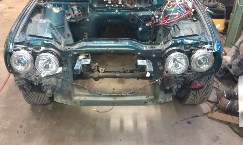
Then rad mounted much further forward than is standard:
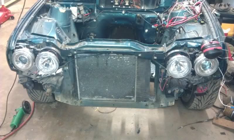
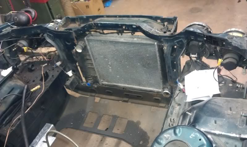
Its just held in with lock wire in these pictures, but some brackets are on the "to do" list.
Then some bumper mods to let in as much air as poss....
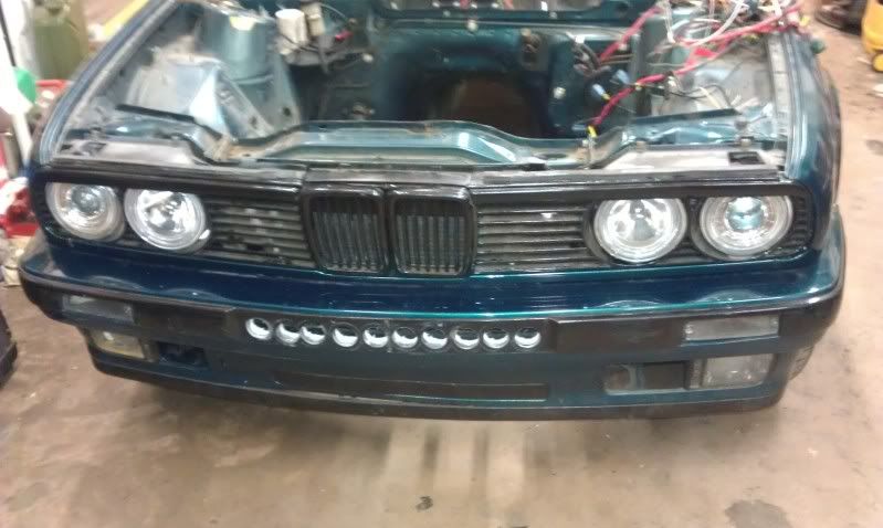
What this pic doesnt show is the huge hole that has been chopped out behind the bumper, so hopefully the flow should be adequate to cool the V8. (This is a bit of an optimistic opinion, but if push comes to shove, a 2nd rad in the rear can be installed)
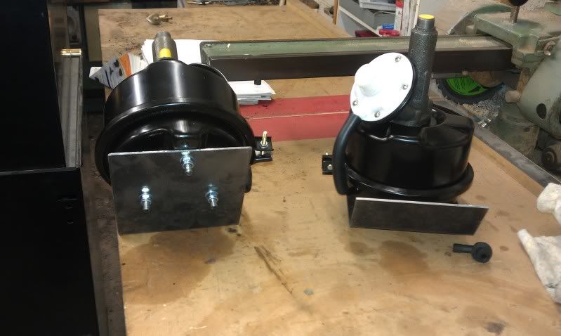
Then the brake parts arrived, so we started work on getting the car to stop!
This:
Plus this:
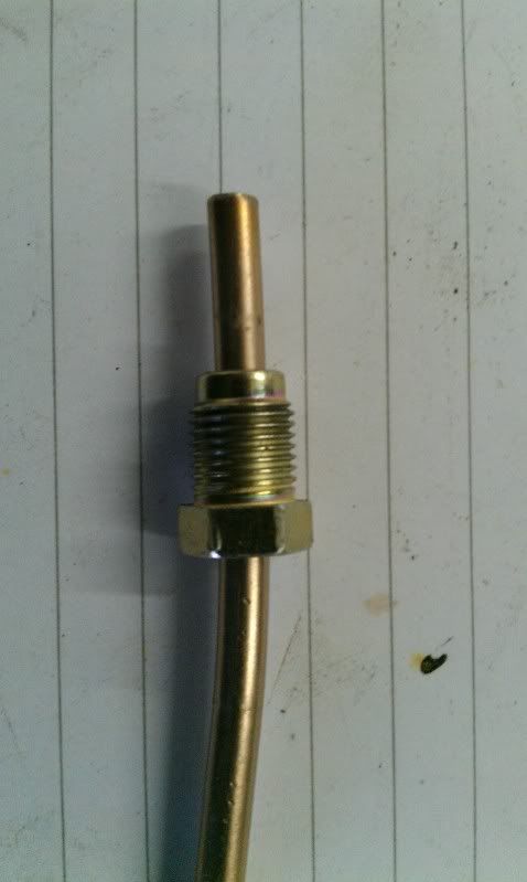
Equals this:
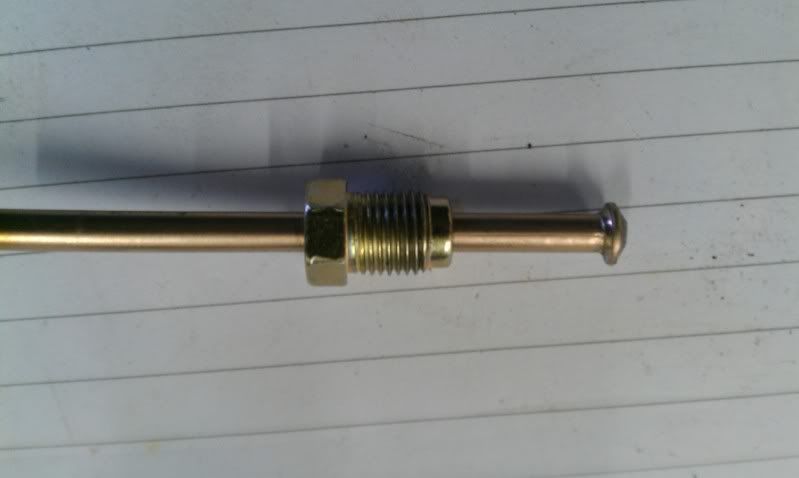
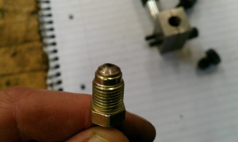
Making hard lines is much easier and cheaper than messing with -3 braided hose, so the whole system will be done using hard pipes.
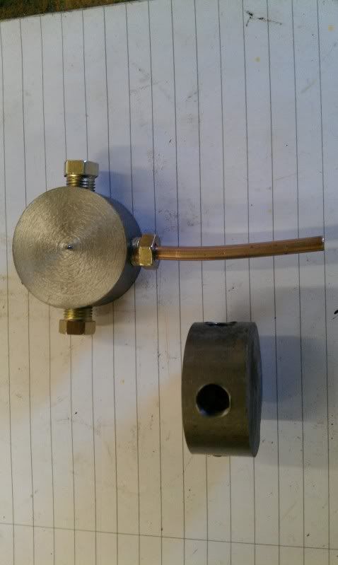
The system will be as shown here. Ignore the mistake on the schematic, the rear left is obviously not the front right lol.
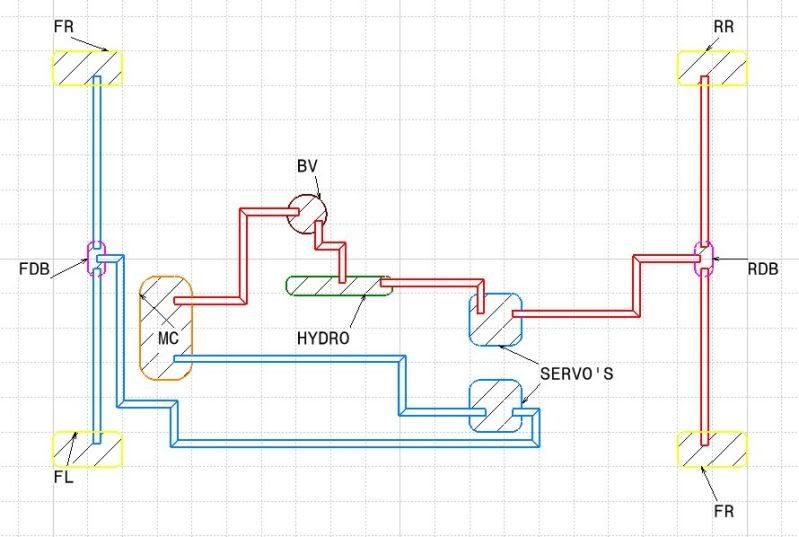
As you can see, both circuits of the master cylinder will be used, with one circuit heading to a remote servo, then to a distribution block and finally to each front caliper.
The rear circuit is a touch more complex, with the fluid exiting the 2nd master cylinder union, heading to the bias valve, then to the hydro, out of the hydro to the 2nd remote servo and to the rear wheels via a 2nd distribution block.
The system was designed this way so that we could have adjustable rear brake bias, whilst at the same time having a hydro for the rears that is servo assisted and therefore very effective at locking the rears. We hope.
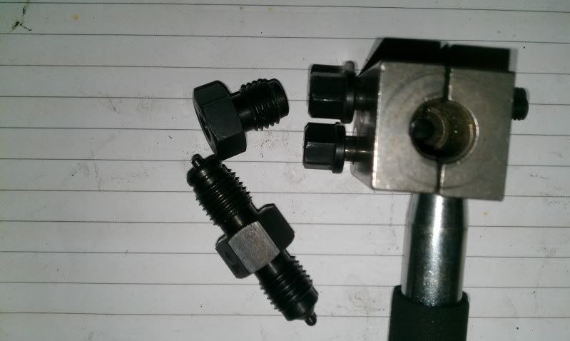
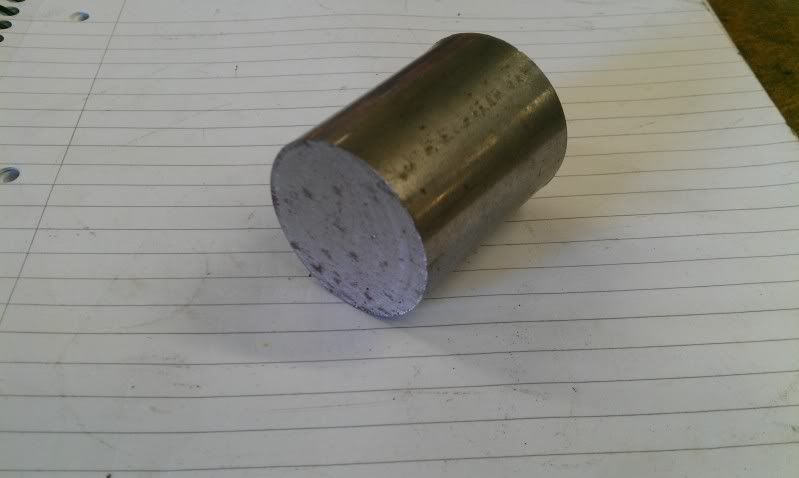
So, distribution blocks. Start with this:
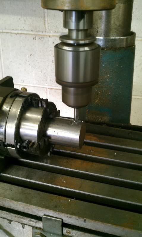
A little milling machine action:
Followed by some tidying, and we ended up with these:
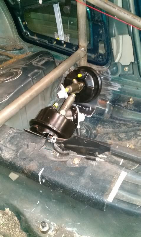
Then we needed to knock up some brackets to mount the remote servos:
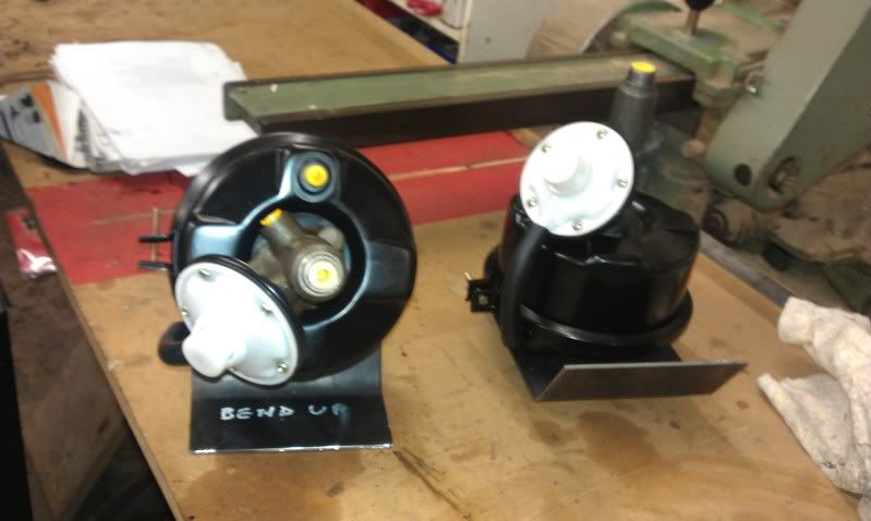
Which then needed to be mounted in the car:
Then we moved on to the pipe work. Excuse the dodgy bends, they will be much nicer!
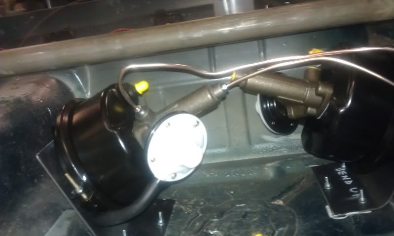
We also needed to mount the bias valve and hydo wand:
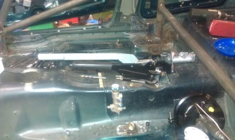
With that all done, we managed to get everything piped up quite late on in the day and were able to test everything out.
Even without vacuum to the remote servo units, the brakes feel nice, and the hydro wand works at least as well as the standard hand brake, so everything should be sweet!
Next time, some exhaust work. I hope.
We managed to fit in some time on the car between doing the respective family things, so here is the progress david and I made over the festive period.....
The brake and exhaust parts we were waiting for didnt turn up as early as expected, so we decided to get the rad mounted as a fill in job to begin with. So front end off!
Then rad mounted much further forward than is standard:
Its just held in with lock wire in these pictures, but some brackets are on the "to do" list.
Then some bumper mods to let in as much air as poss....
What this pic doesnt show is the huge hole that has been chopped out behind the bumper, so hopefully the flow should be adequate to cool the V8. (This is a bit of an optimistic opinion, but if push comes to shove, a 2nd rad in the rear can be installed)
Then the brake parts arrived, so we started work on getting the car to stop!
This:
Plus this:
Equals this:
Making hard lines is much easier and cheaper than messing with -3 braided hose, so the whole system will be done using hard pipes.
The system will be as shown here. Ignore the mistake on the schematic, the rear left is obviously not the front right lol.
As you can see, both circuits of the master cylinder will be used, with one circuit heading to a remote servo, then to a distribution block and finally to each front caliper.
The rear circuit is a touch more complex, with the fluid exiting the 2nd master cylinder union, heading to the bias valve, then to the hydro, out of the hydro to the 2nd remote servo and to the rear wheels via a 2nd distribution block.
The system was designed this way so that we could have adjustable rear brake bias, whilst at the same time having a hydro for the rears that is servo assisted and therefore very effective at locking the rears. We hope.
So, distribution blocks. Start with this:
A little milling machine action:
Followed by some tidying, and we ended up with these:
Then we needed to knock up some brackets to mount the remote servos:
Which then needed to be mounted in the car:
Then we moved on to the pipe work. Excuse the dodgy bends, they will be much nicer!
We also needed to mount the bias valve and hydo wand:
With that all done, we managed to get everything piped up quite late on in the day and were able to test everything out.
Even without vacuum to the remote servo units, the brakes feel nice, and the hydro wand works at least as well as the standard hand brake, so everything should be sweet!
Next time, some exhaust work. I hope.
Gassing Station | Readers' Cars | Top of Page | What's New | My Stuff