AWD Civic Coupe Turbo Build
Discussion


 t who will ruin your day.
I know what you mean, its not that im relaxed about crime around us, i just didnt expect it. Glad to know it wasnt though. On another note, im still waiting on the lexan window companied to get back to me, im not sure if the bank holiday is slowing things down but if they dont want my business lol
Good day all!
Ive managed to make a bit of progress, Plastics4Performance have agreed to do a group buy deal with me, im trying to drum up 5 or more people on a forum im registered as a trader. 20% discount isnt bad at all..
Whilst im sorting out that, i decided to remove the rear glass and do a few jobs. I needed to finish welding up the rear wing sub structure and the radiator supports, made easier without a rear window i must say..
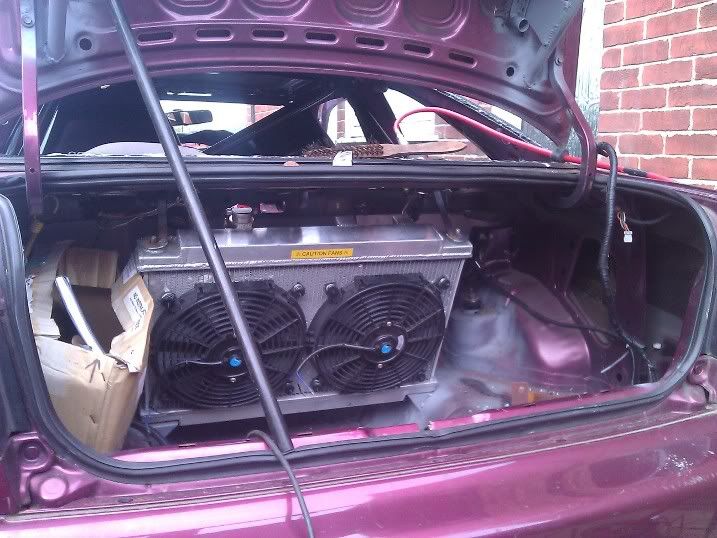
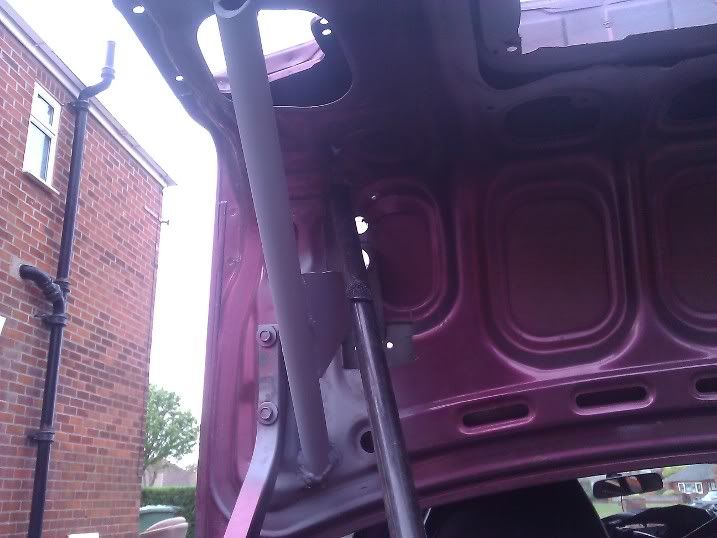

ive also cut out the outer skin so the wider wheels can pass under through to the new extended arches. The left hand side really was rubbish but the drivers side is perfect, rather happy with it. Neither are perfect but they are strong and do the trick..
On another note, whilst there are Ford owners on here.. Somebody asked me to produce a device which would allow a standard ford radio stalk to control anything, but in this case a Race-Technology dash.. Here it is, concept to handed over in 3 days.. not bad i feel lol

(LEDs in the video simulate the inputs to the dash)
Ive managed to make a bit of progress, Plastics4Performance have agreed to do a group buy deal with me, im trying to drum up 5 or more people on a forum im registered as a trader. 20% discount isnt bad at all..
Whilst im sorting out that, i decided to remove the rear glass and do a few jobs. I needed to finish welding up the rear wing sub structure and the radiator supports, made easier without a rear window i must say..
ive also cut out the outer skin so the wider wheels can pass under through to the new extended arches. The left hand side really was rubbish but the drivers side is perfect, rather happy with it. Neither are perfect but they are strong and do the trick..
On another note, whilst there are Ford owners on here.. Somebody asked me to produce a device which would allow a standard ford radio stalk to control anything, but in this case a Race-Technology dash.. Here it is, concept to handed over in 3 days.. not bad i feel lol
(LEDs in the video simulate the inputs to the dash)


Thanks for that mate, I do have a blue lab coat if that helps lol.. don’t wear it though..
Ive been so busy recently I havnt really been able to look at the civic, but I set a few hours aside the other day to finish the drive by wire..
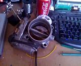
Im not sure whether I mentioned it but I have moved away from my own throttle body design and decided to look for an OEM alternative.
I found an Audi RS4 throttle body in the same diameter as my own (76mm), cheap too.. I bought it. With some small modification of the hole sizes, I managed to get it to fit my intake manifold. Albeit needing allen head bolts for clearance..
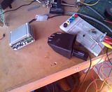
I then modified my drive by wire controller to drive it directly. This is the result of the efforts;
As you can see, the throttle plate is unacceptably jittery.. This is because the motor is trying to seek the position at full speed (100% duty).
I decided to take the “chip enable” pin of the h-bridge IC, and connect it to the spare PWM pin of the PIC. This would work as a “chopper” circuit. I then designed an algorithm which would run the motor at full duty cycle but reduce the duty cycle the closer it got to the intended target position. By doing it like this there is no overshoot.
There is a scaling factor in the software which I can adjust to get the best balance between speed and jitter. In the video below it was set to 5, but afterwards I adjusted it to 10, and that was too far and the jitter came back.
Im going to have another fettle and try to bring it back tonight..
I can pretty much declare it finished now. And im rather happy, plus im using the dual pots in the Audi throttle to continuously perform self tests as to whether the system is working and whether both the sensors agree..

Ive been so busy recently I havnt really been able to look at the civic, but I set a few hours aside the other day to finish the drive by wire..
Im not sure whether I mentioned it but I have moved away from my own throttle body design and decided to look for an OEM alternative.
I found an Audi RS4 throttle body in the same diameter as my own (76mm), cheap too.. I bought it. With some small modification of the hole sizes, I managed to get it to fit my intake manifold. Albeit needing allen head bolts for clearance..
I then modified my drive by wire controller to drive it directly. This is the result of the efforts;
As you can see, the throttle plate is unacceptably jittery.. This is because the motor is trying to seek the position at full speed (100% duty).
I decided to take the “chip enable” pin of the h-bridge IC, and connect it to the spare PWM pin of the PIC. This would work as a “chopper” circuit. I then designed an algorithm which would run the motor at full duty cycle but reduce the duty cycle the closer it got to the intended target position. By doing it like this there is no overshoot.
There is a scaling factor in the software which I can adjust to get the best balance between speed and jitter. In the video below it was set to 5, but afterwards I adjusted it to 10, and that was too far and the jitter came back.
Im going to have another fettle and try to bring it back tonight..
I can pretty much declare it finished now. And im rather happy, plus im using the dual pots in the Audi throttle to continuously perform self tests as to whether the system is working and whether both the sensors agree..
Sounds like a much better job to me! Stick to OEM h/w were possible.
here's one i did earlier

It's amazing just how much time you can spend coding and testing once you start, i'm currently developing my crank angle windowed knock controller (using a TPIC8101 chipset) and it's taking up FAR too much of my time........ ;-)
here's one i did earlier
It's amazing just how much time you can spend coding and testing once you start, i'm currently developing my crank angle windowed knock controller (using a TPIC8101 chipset) and it's taking up FAR too much of my time........ ;-)
Lol SNAP.. thats a great project mate..
i like the idea of the RS232 interface.. i was considering a laptop interface for mine but i wanted to be able to make adjustments quickly if necessary...
lol that sounds like an interesting idea, im currently working on an injector duty cycle / boost controlled water/meth injection for my own car..
A couple of points you might find useful with BOSCH throttles:
1) the D bit in PID is really usefull, because the motor inertia dominates (because it is referenced to the throttle velocity by about a 19x gear ratio!)
2) "fuzy" gains bring big benefits in providing both precision (small increment accuracy/stability) and large high speed "step" response capabilities
3) use dynamic braking at the top and bottom of the travel to prevent the throttle hitting it's hard mech stops (which will knacker the gear train in short order)
4) if your throttle has a "limp home" angle (i.e. it is sprung a little bit open passively, usually about 3 to 5 deg open) then having a very non linear control term that only operates in that zone makes small angle control much much easier
5) make sure you include an adaptive "sweep" logic to learn the max/min position to prevent angle drift (mine does this on key-off rather than key-on as the throttle is more likely to be warm at that point. It also ratchets these values down every 10th key on to ensure they stay valid no matter which way the pots age.
Hopefully my knock box is going to be pretty smart, it reads the crank/cam sensor, so can do proper crank angle windowed and cylinder specific knock signal integration (with filtered/band pass signal processing). it then DACs out a "retard" signal to my EMS as necessary to request spark retard on a cylinder by cylinder basis ;-)
there are some good points, ive been thinking about the adaptive braking.. its a good idea, i think i should be able to deal with it in software as opposed to changing the hardware any more..
I also like the idea of learning the backstops, very clever there..
and i really like your idea about the windowed knock, id love to do something similar in future actually.. I dont know whether i would want it to be directly in the ecu feedback loop but the windowed approach to a single knock sensor is very clever.. how are you dealing with the fact that the sensor(s) will be physically closer to certain cylinders than others.. or is that in the signal processing?
Ive looked up the chip, its a nice little package, analogue output and SPI control.. very neat..
For dynamic braking on the throttle plate, i set a velocity threshold, above which as the plate approaches the end stops the H bridge is set to brake (2 x lower FETS = ON) and the PWM duty is ramped up as it approaches the physical stop. If the plate isn't moving fast, no dynamic brake is selected and the PWM is just controlled as normal by the PID controller on position error. As the D term is velocity anyway (previous position - current position) it's easy to use and is a completely software only strategy
When we first went fly-by-wire on the WRC cars the scrutineers weren't terribly happy by the lack of a powerful return spring (actually, WRC has NO spring at all, for max response reasons). However we demonstrated the systems potential control power by using the throttle plate to chop carrots in half when closing (we tried to get the scrut's to stick their fingers in the throttle but they refused ;-)
The S-N-R is different for each knock signal for various reasons, not just acoustic transmission distance between cylinders and sensor (that is actually a fairly small effect due to the lack of characteristic damping in the critical block frequency response range), however i just use a cylinder specfic "gain" offset. (you have to move the amplification gain anyway with rpm and load to keep the integrator output at the correct magnitude to allow a decent determination of the knocking threshold)
The TPIC8101 is a nice little ASIC, makes KCS pretty easy tbh. I just use the SPi, don't bother with the analogue output (other than to scope during developement). However the SPi interface is pretty clumbsy and the datasheet includes more errors in it that i think i have ever seen before!!
Edited by anonymous-user on Thursday 31st May 23:01
good point..
Unfortunately i didnt build my own mosfet bridge.. i used the L298, dual full bridge driver.. It can manage 2 - 2.5A per channel at a push, i measured the maximum current consumption of the throttle under manual load at just over 4A.. Ive run the h bridge in parallel to double the capacity. Ive just looked over the datasheet again. Cant believe i actually missed the braking mode, im assuming its the same as shorting the coil to GND the same way as turning on the lower mosfets..
it shouldnt be too difficult to write it into the software.. I see your logic though, only use the braking mode when a high rate of acceleration is being used..
There seem quite a few variables to accommodate during the development of your system.. rpm, gain .etc id be really interested in how you tackle the signal processing element i really would.. I didnt realise the IC actually transmitted the data via SPi too, i assumed you would need to use a separate ADC.. It must be a pretty decent data rate on the SPi.. Im running a Phormula KS4 on mine at the moment, i wouldnt actually mind (using the KS4 to prove it at least) to make my own. It would be nice to have a steaming RS232 output with the 4 channels on which i could datalog. I would also be keep to add the ability to retard the ignition at a later date.. I might request a sample of the IC and have a play.. Unfortunately im stupidly busy with other peoples' projects at the moment lol
Edited by purplecivicturbo on Friday 1st June 07:46
purplecivicturbo said:
good point..
Unfortunately i didnt build my own mosfet bridge.. i used the L298, dual full bridge driver.. It can manage 2 - 2.5A per channel at a push, i measured the maximum current consumption of the throttle under manual load at just over 4A.. Ive run the h bridge in parallel to double the capacity. Ive just looked over the datasheet again. Cant believe i actually missed the braking mode, im assuming its the same as shorting the coil to GND the same way as turning on the lower mosfets..
it shouldnt be too difficult to write it into the software.. I see your logic though, only use the braking mode when a high rate of acceleration is being used..
There seem quite a few variables to accommodate during the development of your system.. rpm, gain .etc id be really interested in how you tackle the signal processing element i really would.. I didnt realise the IC actually transmitted the data via SPi too, i assumed you would need to use a separate ADC.. It must be a pretty decent data rate on the SPi.. Im running a Phormula KS4 on mine at the moment, i wouldnt actually mind (using the KS4 to prove it at least) to make my own. It would be nice to have a steaming RS232 output with the 4 channels on which i could datalog. I would also be keep to add the ability to retard the ignition at a later date.. I might request a sample of the IC and have a play.. Unfortunately im stupidly busy with other peoples' projects at the moment lol
I didn't build my own bridge either, I used one of the Infineon Automotive ranges smart output drivers designed specifically for driving automotive loads, can't actually remember which one now without going to look ;-)Unfortunately i didnt build my own mosfet bridge.. i used the L298, dual full bridge driver.. It can manage 2 - 2.5A per channel at a push, i measured the maximum current consumption of the throttle under manual load at just over 4A.. Ive run the h bridge in parallel to double the capacity. Ive just looked over the datasheet again. Cant believe i actually missed the braking mode, im assuming its the same as shorting the coil to GND the same way as turning on the lower mosfets..
it shouldnt be too difficult to write it into the software.. I see your logic though, only use the braking mode when a high rate of acceleration is being used..
There seem quite a few variables to accommodate during the development of your system.. rpm, gain .etc id be really interested in how you tackle the signal processing element i really would.. I didnt realise the IC actually transmitted the data via SPi too, i assumed you would need to use a separate ADC.. It must be a pretty decent data rate on the SPi.. Im running a Phormula KS4 on mine at the moment, i wouldnt actually mind (using the KS4 to prove it at least) to make my own. It would be nice to have a steaming RS232 output with the 4 channels on which i could datalog. I would also be keep to add the ability to retard the ignition at a later date.. I might request a sample of the IC and have a play.. Unfortunately im stupidly busy with other peoples' projects at the moment lol
Edited by purplecivicturbo on Friday 1st June 07:46
The TPIC8101 makes the knock signal processing really easy, because it does most of it internally! You just have a hardware gain input setup, generally just set to a gain of 1 for most knock sensors, then the ASIC does the anti aliasing filtering, the band pass (via selectable centre frequency on SPI), the second stage gain (again via SPI), and the integration time constant (SPI again). The hardest part is decoding the crank sensor into a windowed "integrate now" signal, which really takes a software "crank angle clock" to do with proper resolution (1degCA in my case). As the duration of this window is fixed in the crank angle domain, it is variable in the time domain (gets shorter with higher rpm) hence you need to increase the integrator time constant with engine rpm. I use an adaptive gain strategy that used a median filter followed by a rolling average smoothing filter to establish the mean signal amplitude. The code then increases or decreases the gain to keep this value at about 25% of the output range (which is 10b via SPI). On top of all that you need to use look up tables with speed(rpm) and load(MAP) to set the "knock" threshold, make sure you don't update the background average on true knock events (to avoid saturation of the mean signal), Then one a knock event is found, this is allocated to the current firing cylinder, and a retard step is called for that cylinder (and the DACout set appropriately). Then this retard is gradually decreased on a firing event basis until either no retard is being called, or another knock event occurs for that cylinder and the "step and rampin" process starts again.
The SPI has a max clock frequency of 10Mhz, and even at 7000rpm on a 4cyl, there is 2.8ms between firing events, so not really that difficult to keep up with.
Simples ;-)
Edited by anonymous-user on Friday 1st June 19:50
It sounds a vary capable IC.. I have ordered 3 samples from TI, apparently they have already been sent..
I suppose having the uC determining the engine position isnt too difficult. I know in my case (being a honda) the ECU has 1/4/24 pulse triggers for every rotation of the CAMs not the crank, so it isnt too hard to use it.. Plus its only a VR sensor.
This sounds like a project which would benefit from a PC interface for calibration..
Fair enough with the H bridge, sometimes its easier to make your own, as i did with my rear wing actuator lol

Gassing Station | Readers' Cars | Top of Page | What's New | My Stuff