Drayton Manor Metro Race Car
Discussion


Hi all,
I race in the Drayton Manor Metro Cup - http://www.mgmetrocup.co.uk/. Not the most glamorous series, but brilliant fun and value for money. Over the winter I’ve been changing my car from a class B car, to class C spec, and I thought I’d try and put together a write up, which I've split up into a few pieces.
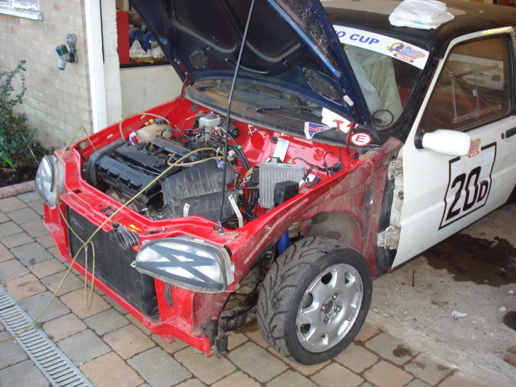
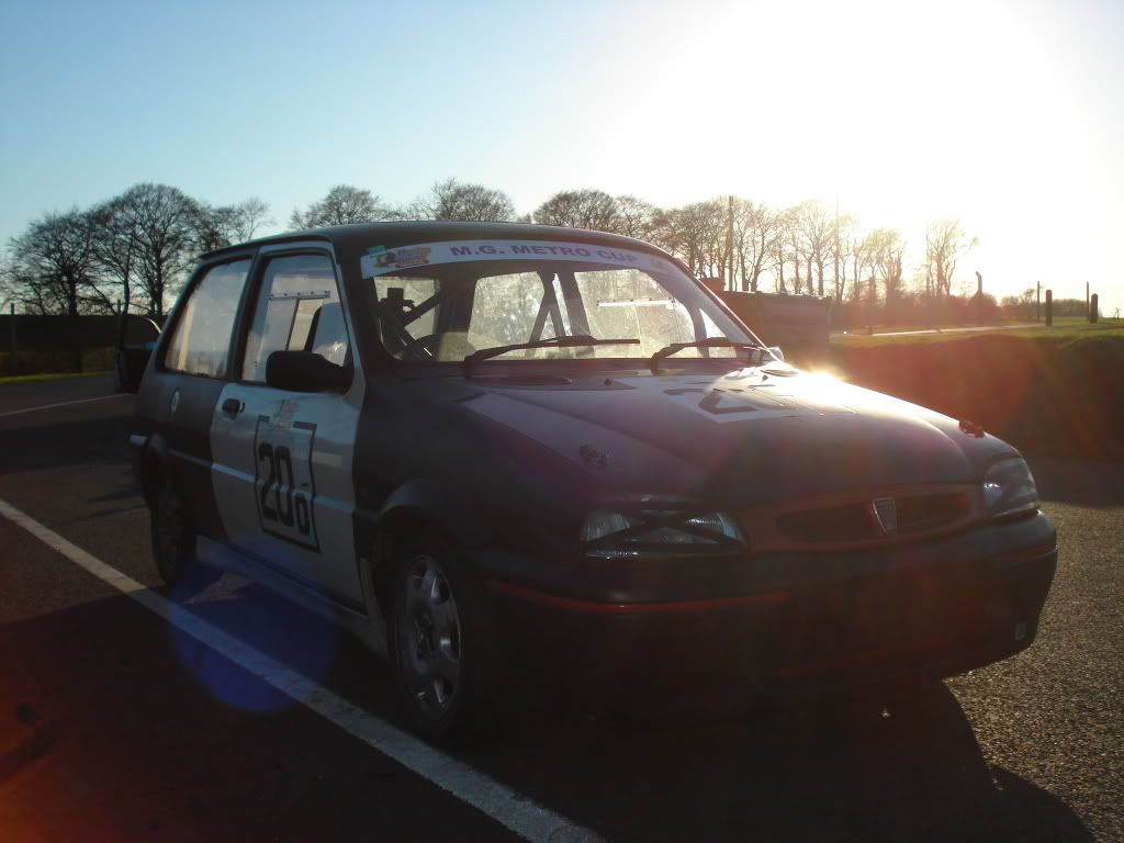
Class B covers fairly standard spec GTi’s, and was where I raced last year. Class C allows a few upgrades, such as stickier tyres, lower final drives, LSD, rear dampers etc. This is the top class, and I’ll be racing against 1380 A series cars, and metro turbo’s. The pic below shows the car at the end of last season.
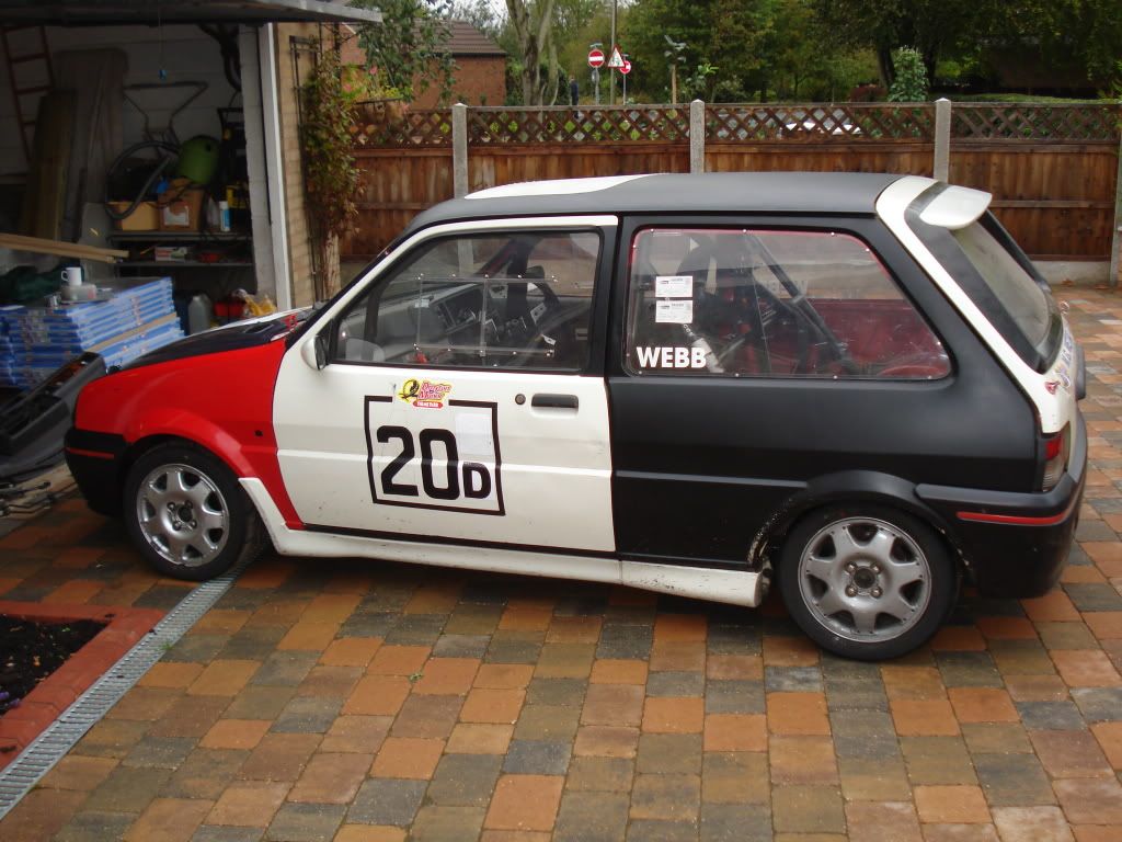
My old GTi's shown in this pic. The damage doesn't look too bad in this one, but the shell was a mess inside.
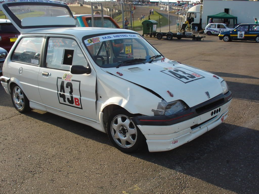
I managed to write my GTi off last year in the first race of the season at Brands, and spent the rest of the season recovering from a very rapid reshell. I didn’t miss any races, but it took most of the season to get the car back to it’s previous spec. The new shells not too bad, but it has an interesting paint scheme. This was made even worse by me speeding up the build by using the doors and boot off my old GTi.
Unfortunately I tend to think about things and tinker. Most of the things on my car tend to customised, and done slightly differently to everybody else. This means most jobs take longer than they really should…I like to learn how to do things as well….
The first job I wanted to tackle was the rear dampers. The plan was to get all the structural jobs out the way first, so the car could be stripped to a rolling shell, and painted. As time went on it became clear that to do this would take more time than I really wanted it to. Tom, who was going to paint it is building two metro race cars at the moment, so wouldn’t have the time to do it either. It was a shame, as the rough paint job belies the level of attention the car has enjoyed (or so I’d like to think).
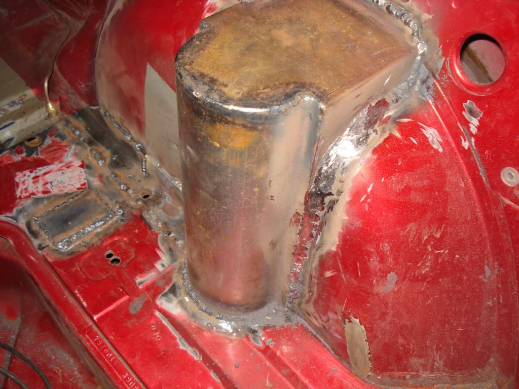
Originally As standard metro’s didn’t have separate rear dampers, the rear of the car needs ‘turreting’ to allow rear dampers to be fitted. I already had a kit for doing this, which sort of made things easier. Being fairly independent, I wanted to weld the turrets in myself. I’d not got a MIG set, or used one before, but you can’t let things like that put you off!
There was some other welding that needed doing at the same time, so I needed to drop the rear sub frame and fuel tank. Taking the rear subframe off gave me something to practice welding on as, I could seam weld it fairly easily.
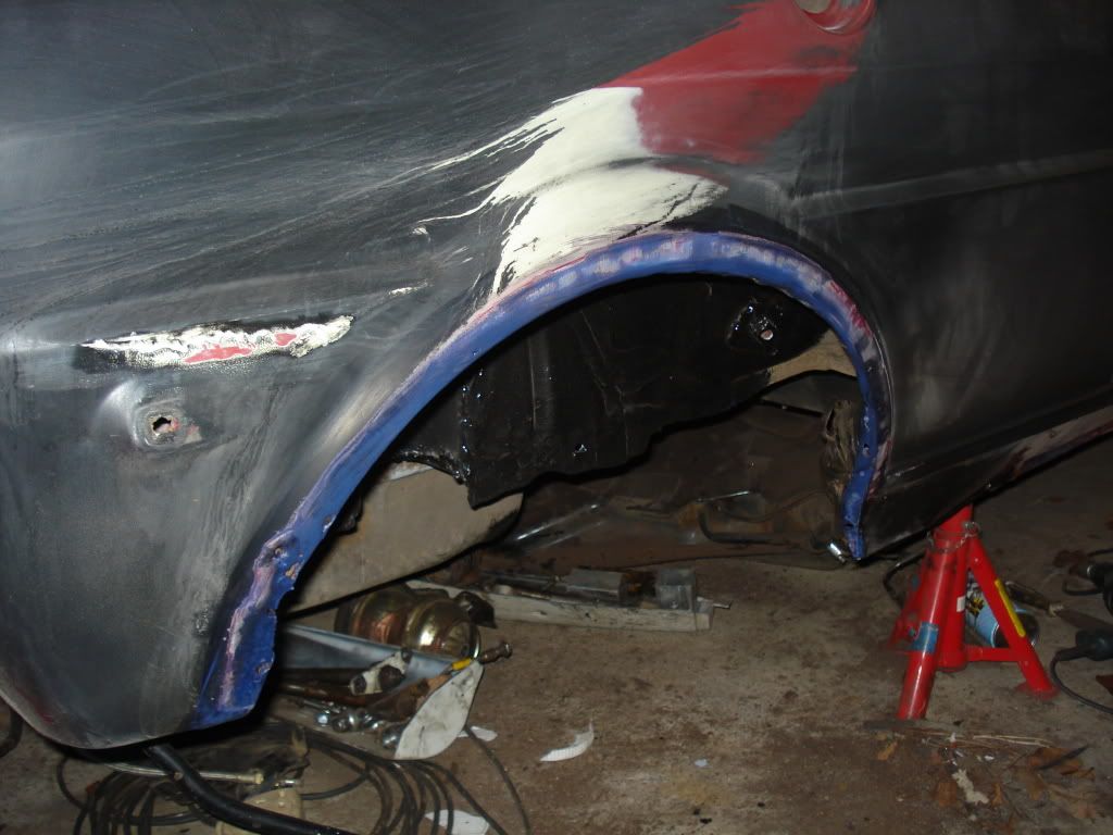
After lots of marking out, and prevaricating, I attacked the wheel arches with an angle grinder. I was fairly conservative, as my view was the less car I cut out, the better.
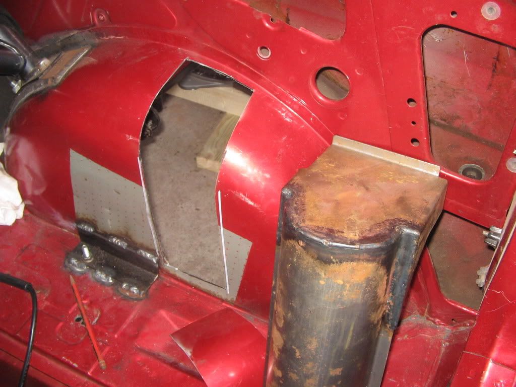
One I had the arches cut, I could offer up the turrets. I quickly discovered they weren’t exactly a perfect fit. The rear side was set back about 8mm from the arch. I decided to fill this with some 8mm steel. Despite a small weight penalty, there would be an increase in strength. As I was feeling slightly paranoid about the strength of the passenger side wheelarch, this wasn’t such a bad thing.
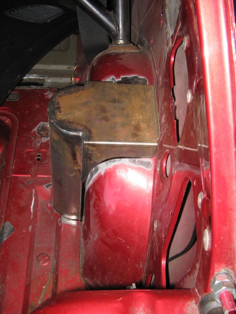
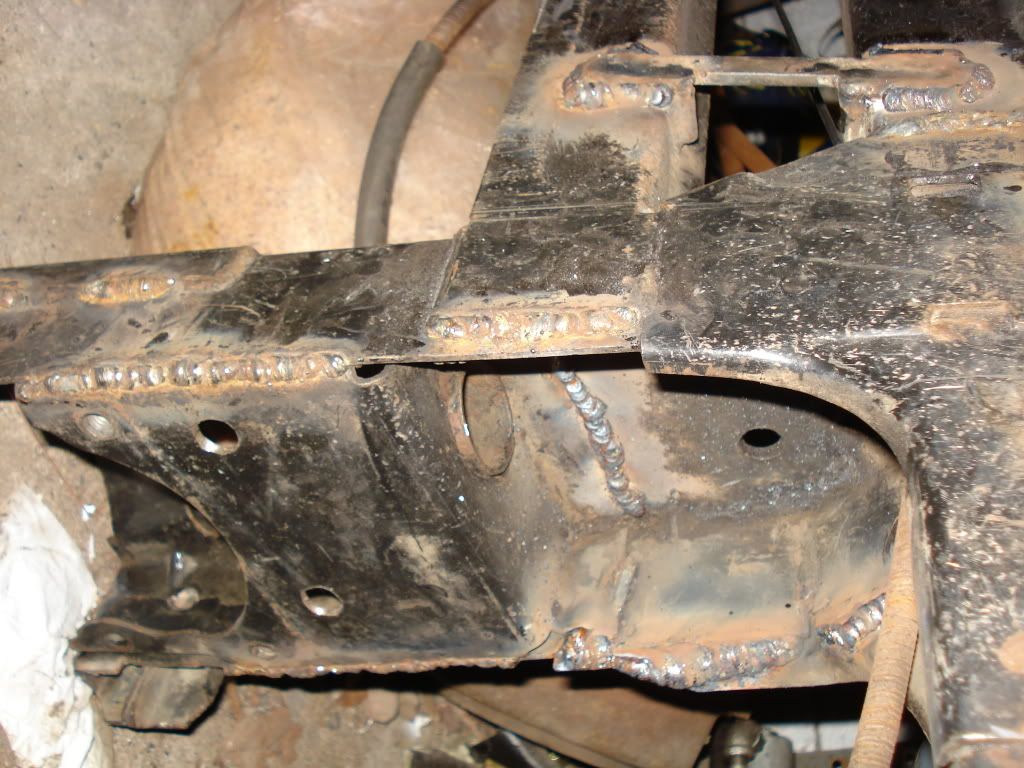
After stripping back the paint I started welding the turrets in, drivers side first. I struggled a bit here. There’s a big difference between welding some nice clean metal on the bench, and assuming some sort of advanced yoga position in the back of a car, then trying to weld some rusty old metal at a really awkward angle. Where the welds looked rough, I ground them back, and reworked them. I think I was having trouble getting the welder setup perfectly as well. If the wire feeds not smooth life’s so much harder. In the end I was happy there was good strength in the welding, but beautiful it definitely wasn’t. The later welds were much better than the first ones though. Luckily at this point I discovered the abrasive flapper paddles for grinders (they’re like loads of strips of sand paper on the wheel), these made the grinding loads easier and neater. Once I got the welds looking tidier, I stated on some of the other rust patches.
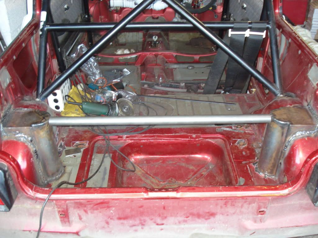
There had been some corrosion on the inner wheel arch, which had weaken the boot floor – not good when the rear bump stop mounts here. The floor had started to push up under the constant pounding it was taking. Luckily a mate had welded some angle in as reinforcement. I took the opportunity to extend this angle along the wheel arch, and repeated it on the other side. This reinforces the bump stop mounting, so no more worries there! The next problem was two bubbling areas in the boot floor. Stripping the paint off revealed two 50p size holes. This was in addition to the hole that had formed above the rear brake pipe mounting bracket. I fabbed up some plates to cover the holes, and welded them in. Not the prettiest jobs in the world, but much better than rusty bits. Whilst I was at it I welded the washers in that I’d made for where the rear subframe is bolted on. Originally there was a big rubber pad underneath the boot floor. These rubber pads were junked, replaced with alloy, and bolted through into the boot floor. The other mounts to the rear subframe have a rubber pad in them. I made these mounts solid by welding some steel ‘across’ the rubber. I’d done this before, but made a neater job on this set of mounts.
Now I’d pretty much done all the welding in the back, I could weld the bracing bar in. Originally I planned to extend my roll cage to bolt onto the turret, but the Blue Book prohibits modifying homologated cages. I’d rather leave the stickers on my Safety Devices Cage, so I used the steel I’d bought to do it as a bracing bar to run between the turret tops. I left this till last in case it got in the way. For dampers, it’s probably overkill, but since the cars underweight, and I already had the steel, it made sense. I wanted the back end to be strong enough for coilovers, even though I don’t plan to fit them at the moment. After finishing the welding, it was simply a job of tidying up the welds with the grinderette.
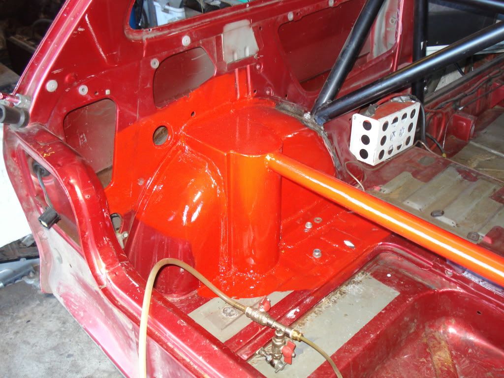
I put some POR15 on as a first coat, then used Hammerite as a top coat. Black for the wheel arches, as I just wanted a good thick covering, and red for the interior, as it was the closest paint I had! As the car will get painted at some point, I’m not too worried about it. I can always get some paint of the right colour and tidy it up. I tend to carry a lot of gear in the back, so it will probably look tatty after a while anyway.
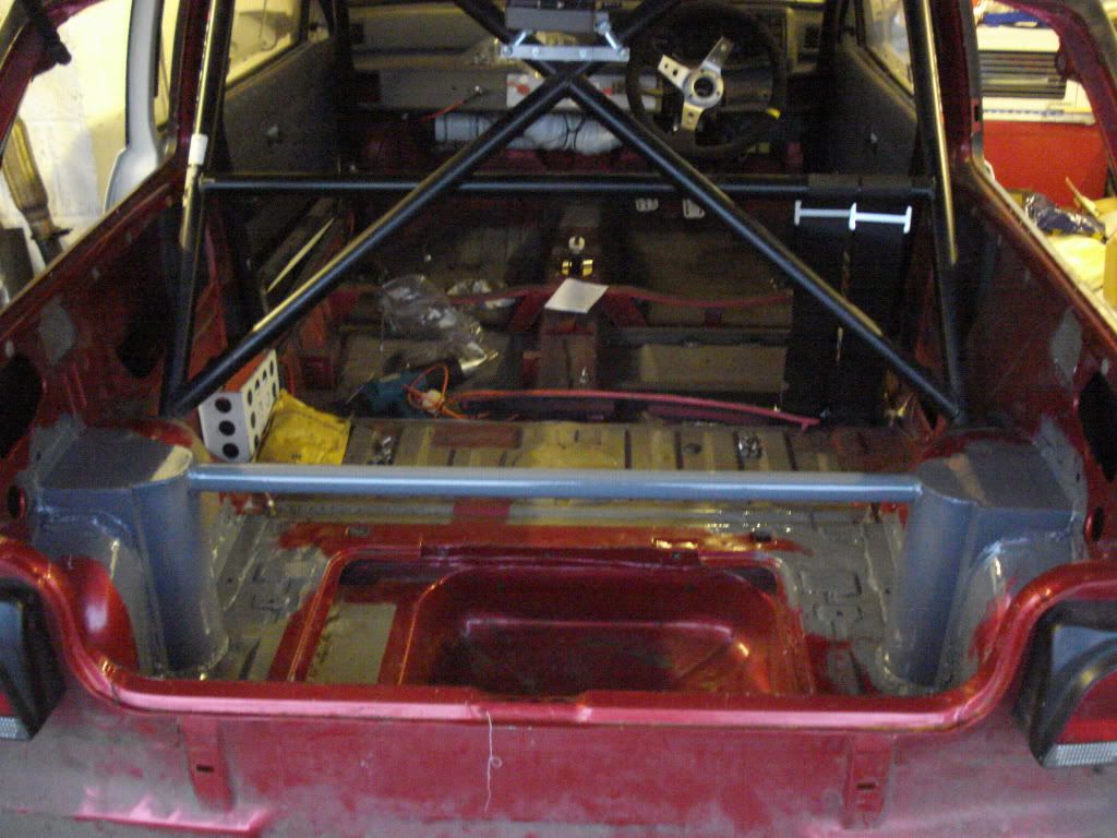
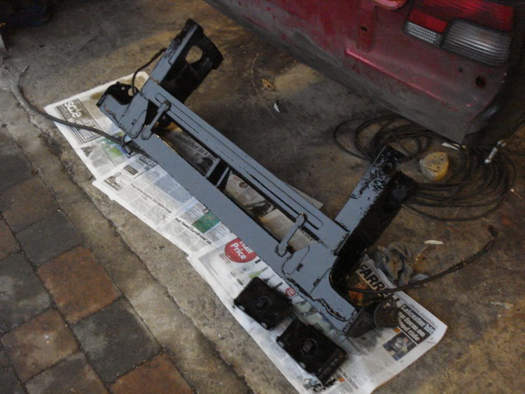
As the POR15 didn’t go very far, the rear subframe and mounts got lashings of black Hammerite. Again I just wanted a nice thick layer, as it’s going to take a hammering underneath the car. Not a perfect job, but it should stop it rusting.
I race in the Drayton Manor Metro Cup - http://www.mgmetrocup.co.uk/. Not the most glamorous series, but brilliant fun and value for money. Over the winter I’ve been changing my car from a class B car, to class C spec, and I thought I’d try and put together a write up, which I've split up into a few pieces.
Class B covers fairly standard spec GTi’s, and was where I raced last year. Class C allows a few upgrades, such as stickier tyres, lower final drives, LSD, rear dampers etc. This is the top class, and I’ll be racing against 1380 A series cars, and metro turbo’s. The pic below shows the car at the end of last season.
My old GTi's shown in this pic. The damage doesn't look too bad in this one, but the shell was a mess inside.
I managed to write my GTi off last year in the first race of the season at Brands, and spent the rest of the season recovering from a very rapid reshell. I didn’t miss any races, but it took most of the season to get the car back to it’s previous spec. The new shells not too bad, but it has an interesting paint scheme. This was made even worse by me speeding up the build by using the doors and boot off my old GTi.
Unfortunately I tend to think about things and tinker. Most of the things on my car tend to customised, and done slightly differently to everybody else. This means most jobs take longer than they really should…I like to learn how to do things as well….
The first job I wanted to tackle was the rear dampers. The plan was to get all the structural jobs out the way first, so the car could be stripped to a rolling shell, and painted. As time went on it became clear that to do this would take more time than I really wanted it to. Tom, who was going to paint it is building two metro race cars at the moment, so wouldn’t have the time to do it either. It was a shame, as the rough paint job belies the level of attention the car has enjoyed (or so I’d like to think).
Originally As standard metro’s didn’t have separate rear dampers, the rear of the car needs ‘turreting’ to allow rear dampers to be fitted. I already had a kit for doing this, which sort of made things easier. Being fairly independent, I wanted to weld the turrets in myself. I’d not got a MIG set, or used one before, but you can’t let things like that put you off!
There was some other welding that needed doing at the same time, so I needed to drop the rear sub frame and fuel tank. Taking the rear subframe off gave me something to practice welding on as, I could seam weld it fairly easily.
After lots of marking out, and prevaricating, I attacked the wheel arches with an angle grinder. I was fairly conservative, as my view was the less car I cut out, the better.
One I had the arches cut, I could offer up the turrets. I quickly discovered they weren’t exactly a perfect fit. The rear side was set back about 8mm from the arch. I decided to fill this with some 8mm steel. Despite a small weight penalty, there would be an increase in strength. As I was feeling slightly paranoid about the strength of the passenger side wheelarch, this wasn’t such a bad thing.
After stripping back the paint I started welding the turrets in, drivers side first. I struggled a bit here. There’s a big difference between welding some nice clean metal on the bench, and assuming some sort of advanced yoga position in the back of a car, then trying to weld some rusty old metal at a really awkward angle. Where the welds looked rough, I ground them back, and reworked them. I think I was having trouble getting the welder setup perfectly as well. If the wire feeds not smooth life’s so much harder. In the end I was happy there was good strength in the welding, but beautiful it definitely wasn’t. The later welds were much better than the first ones though. Luckily at this point I discovered the abrasive flapper paddles for grinders (they’re like loads of strips of sand paper on the wheel), these made the grinding loads easier and neater. Once I got the welds looking tidier, I stated on some of the other rust patches.
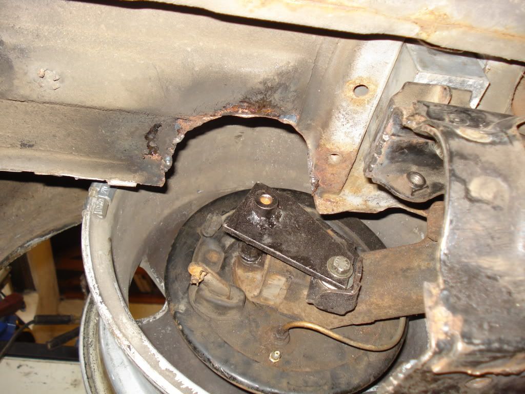
There had been some corrosion on the inner wheel arch, which had weaken the boot floor – not good when the rear bump stop mounts here. The floor had started to push up under the constant pounding it was taking. Luckily a mate had welded some angle in as reinforcement. I took the opportunity to extend this angle along the wheel arch, and repeated it on the other side. This reinforces the bump stop mounting, so no more worries there! The next problem was two bubbling areas in the boot floor. Stripping the paint off revealed two 50p size holes. This was in addition to the hole that had formed above the rear brake pipe mounting bracket. I fabbed up some plates to cover the holes, and welded them in. Not the prettiest jobs in the world, but much better than rusty bits. Whilst I was at it I welded the washers in that I’d made for where the rear subframe is bolted on. Originally there was a big rubber pad underneath the boot floor. These rubber pads were junked, replaced with alloy, and bolted through into the boot floor. The other mounts to the rear subframe have a rubber pad in them. I made these mounts solid by welding some steel ‘across’ the rubber. I’d done this before, but made a neater job on this set of mounts.
Now I’d pretty much done all the welding in the back, I could weld the bracing bar in. Originally I planned to extend my roll cage to bolt onto the turret, but the Blue Book prohibits modifying homologated cages. I’d rather leave the stickers on my Safety Devices Cage, so I used the steel I’d bought to do it as a bracing bar to run between the turret tops. I left this till last in case it got in the way. For dampers, it’s probably overkill, but since the cars underweight, and I already had the steel, it made sense. I wanted the back end to be strong enough for coilovers, even though I don’t plan to fit them at the moment. After finishing the welding, it was simply a job of tidying up the welds with the grinderette.
I put some POR15 on as a first coat, then used Hammerite as a top coat. Black for the wheel arches, as I just wanted a good thick covering, and red for the interior, as it was the closest paint I had! As the car will get painted at some point, I’m not too worried about it. I can always get some paint of the right colour and tidy it up. I tend to carry a lot of gear in the back, so it will probably look tatty after a while anyway.
As the POR15 didn’t go very far, the rear subframe and mounts got lashings of black Hammerite. Again I just wanted a nice thick layer, as it’s going to take a hammering underneath the car. Not a perfect job, but it should stop it rusting.
Thanks for the positive comments. I've put together another update.
I tried to tidy up the matt black paint where it had been stained by leaking fuel. I thought I’d try with some solvents…..Oops! The paint must have been compromised, as it wiped straight off. Of course the upside of matt black paint is it’s fairly easy to fix, so off to Halfrauds. At the same time I had a quick clean up of the bubbling on the arches. They’re well known to rust from the inside, so anything less than replacement is only temporary. The arches were in a worse state then they looked. When I get a chance I’ll have a go at replacing them properly, but it’s a bodge for now. Luckily the paint went on OK, and whilst not perfect it's good enough at a distance.
The dampers need a lower mounting point. The kit I had came with some fairly industrial looking brackets. These bolted on using the existing back plate bolts on the rear trailing arm. Unfortunately one of these bolts passes through a couple of inches of iron trailing arm. The bolt was rusted in and refused to shift. As I could feel a slight wobble in the hub bearing I decided to put a spare arm on. Despite trying with a drill at first, I finally removed the bolt with some sturdy punches, and a violent attack with a mallet. The other side was exactly the same, but this time I went straight for brute force and ignorance.
The brackets took a little bit of fitting to space them properly before I was happy with the way they were sat. Swapping the trailing arms meant I needed to swap the bleed nipple from the brake cylinder, as I’d fitted speed bleeders to make bleeding the brakes easier. The brake cylinders had identical part numbers, but different sized bleed nipples, so I had to swap the whole cylinder. Thanks Delphi!
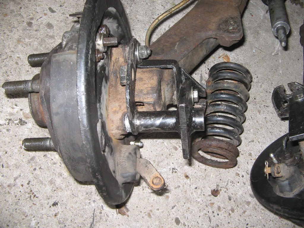
With a rim put on I could get an idea of where the damper would sit. I’d liked to have been able to fit coileovers, but there isn’t much spare room for the springs. I think a damper will end up quite close to the tyre as it is. The turrets are slightly too far back for such a lowered car, though I think they’ll be ok, even hard into the bump stops. The adjuster will need to go at the back though.
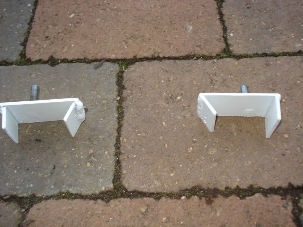
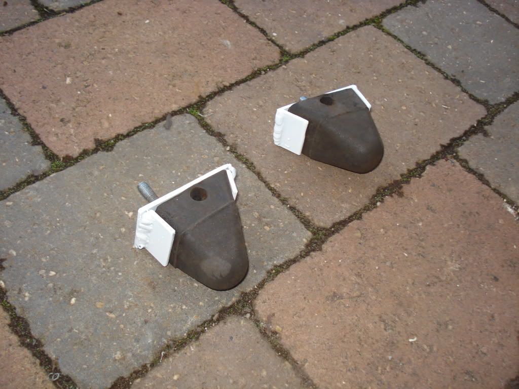
The bump stops at the back were from an MGB. These had been setup to sit just off the suspension arm at normal ride height to help with roll stiffness. Whilst this works quite well, the bump stops had taken a hammering were no longer in good enough shape for this. I had a couple of standard bumpstops that I could fit, but they wouldn’t bolt straight on to my car any more. I therefore had to make a cradle to hold them. I knocked some sheet metal together, I dragged the MIG out again. The welds were much better this time! I then fettled the original mounting holes to allow the units to be bolted on. Hopefully with the redesign, I can get the roll stiffness without having to use the bumpstops as much. The extra rear damping should help, and allow me to get the setup better.
Jim.
I tried to tidy up the matt black paint where it had been stained by leaking fuel. I thought I’d try with some solvents…..Oops! The paint must have been compromised, as it wiped straight off. Of course the upside of matt black paint is it’s fairly easy to fix, so off to Halfrauds. At the same time I had a quick clean up of the bubbling on the arches. They’re well known to rust from the inside, so anything less than replacement is only temporary. The arches were in a worse state then they looked. When I get a chance I’ll have a go at replacing them properly, but it’s a bodge for now. Luckily the paint went on OK, and whilst not perfect it's good enough at a distance.
The dampers need a lower mounting point. The kit I had came with some fairly industrial looking brackets. These bolted on using the existing back plate bolts on the rear trailing arm. Unfortunately one of these bolts passes through a couple of inches of iron trailing arm. The bolt was rusted in and refused to shift. As I could feel a slight wobble in the hub bearing I decided to put a spare arm on. Despite trying with a drill at first, I finally removed the bolt with some sturdy punches, and a violent attack with a mallet. The other side was exactly the same, but this time I went straight for brute force and ignorance.
The brackets took a little bit of fitting to space them properly before I was happy with the way they were sat. Swapping the trailing arms meant I needed to swap the bleed nipple from the brake cylinder, as I’d fitted speed bleeders to make bleeding the brakes easier. The brake cylinders had identical part numbers, but different sized bleed nipples, so I had to swap the whole cylinder. Thanks Delphi!
With a rim put on I could get an idea of where the damper would sit. I’d liked to have been able to fit coileovers, but there isn’t much spare room for the springs. I think a damper will end up quite close to the tyre as it is. The turrets are slightly too far back for such a lowered car, though I think they’ll be ok, even hard into the bump stops. The adjuster will need to go at the back though.
The bump stops at the back were from an MGB. These had been setup to sit just off the suspension arm at normal ride height to help with roll stiffness. Whilst this works quite well, the bump stops had taken a hammering were no longer in good enough shape for this. I had a couple of standard bumpstops that I could fit, but they wouldn’t bolt straight on to my car any more. I therefore had to make a cradle to hold them. I knocked some sheet metal together, I dragged the MIG out again. The welds were much better this time! I then fettled the original mounting holes to allow the units to be bolted on. Hopefully with the redesign, I can get the roll stiffness without having to use the bumpstops as much. The extra rear damping should help, and allow me to get the setup better.
Jim.
Nice project, what dimensions did you use to make the rear solid mounts (the ones that go through the floor)?
Are you using the TF solid mounts on the front subframe? I've just sold a gti that had this done along with solid rear subframe and droop stop spacers on the rear and it handled so well
Are you using the TF solid mounts on the front subframe? I've just sold a gti that had this done along with solid rear subframe and droop stop spacers on the rear and it handled so well
The rear was solidly mounted when I got the original car. They're basically just alloy blocks, drilled through into the subframe. Thinking about it they do look thicker than the rubber pads, but not by a massive amount. I'd have to have a really good think to work out if tilting it back like this has much of an effect. I will solid mount the front subframe, just haven't got round to it yet. I did have some TF solid subframe mounts, but I can only find the front set. If I can't find the rears I'll knock some up using the original rubber ones.
I'm hoping I can get the car handling well. Despite having got some of the setup wrong before, I'm confident I can get it better. There's a few trick bits I've designed for the suspension which will help.
Jim.
I'm hoping I can get the car handling well. Despite having got some of the setup wrong before, I'm confident I can get it better. There's a few trick bits I've designed for the suspension which will help.
Jim.
Cheers. I like to know how things work, and it's good when you learn you can actually do something.
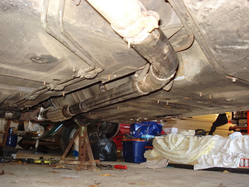
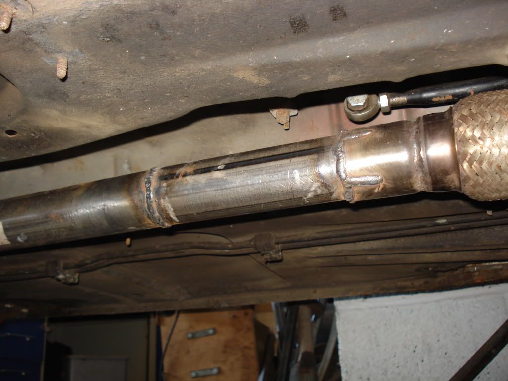
After refitting the tank and rear subframe, I turned my attention to my exhaust. I believe the exhaust is a Janspeed fast road system. It’s pretty quiet compared to the Janspeed race systems, which lack the road variants centre silencer. Pondering this, I got a few bits from Jetex, and made a new straight through centre section to see how much of an effect it would have. It was quite nasty at first, as there was no flexible on the manifold. With less weight to damp the vibrations it was incredibly aggressive. Not wanting to pilot a car that was constantly shaking itself to bits, I ordered a flexible, which ended up being fitted at the far end of the centre section. The engine felt slightly more free revving, though I can’t quantify this. Saved some weight as well. The soundtrack was more spectacular though, with pops and bags. In order to improve this, as well as tidy it up I brought out the welder and welded all the sections together. I put the flexible as close to the manifold as possible, as this meant I could raise the height of the exhaust, and prevent it grounding out as much. I also took the chance to weld some bolts on to act as mounts for the hangers. The welding was much neater than previously, especially as the welder seemed to be feeding smoothly as well.
Jim.
Another update.
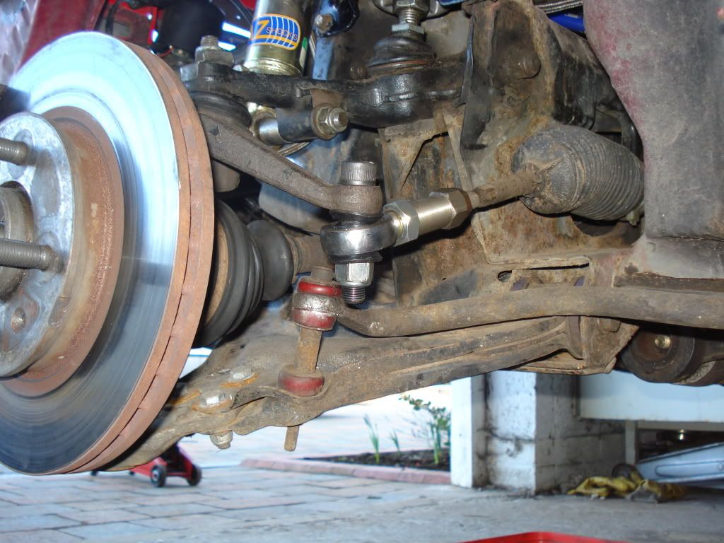
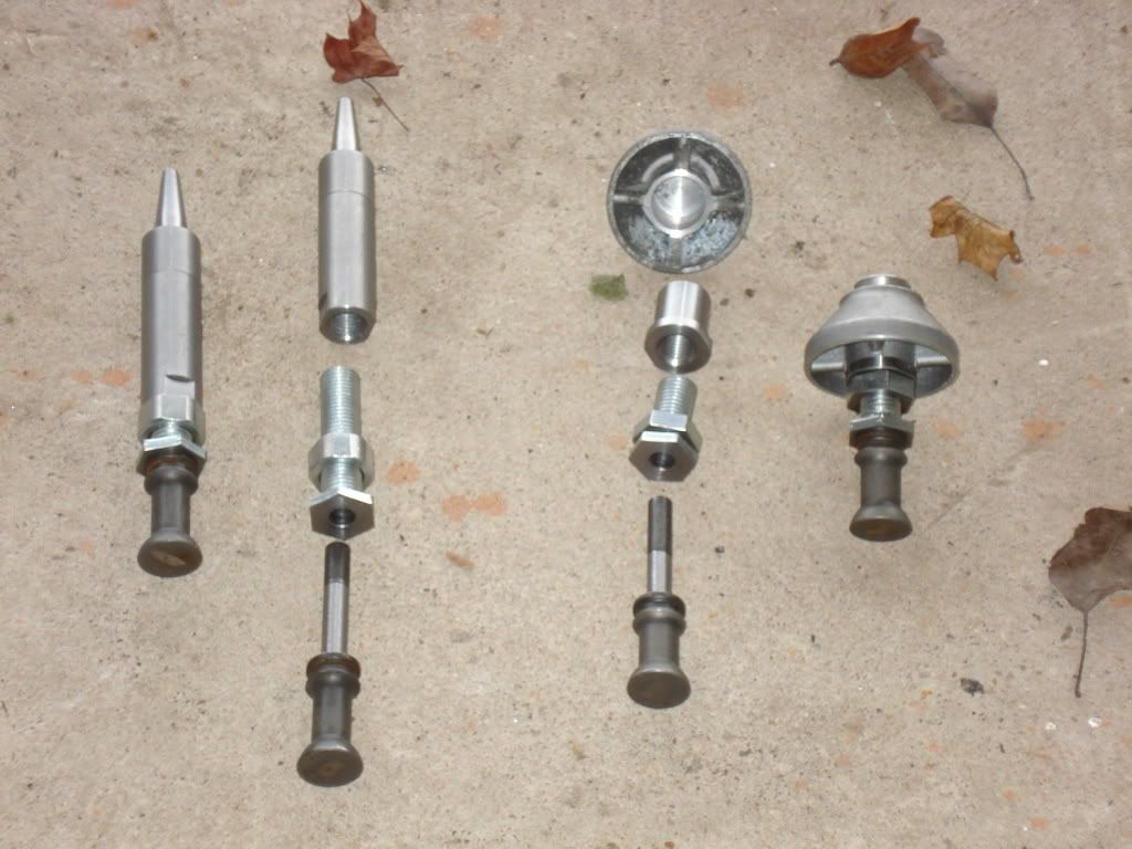
The front end of the car needs some attention. I had previously set up the bump steer, which was quite far off as standard, and even worse after my geometry was altered. To try and improve the setup, I got some converted spherical bearings that could be mounted much closer to the steering arm, hopefully allowing me to improve the bump steer around the new lower ride height. To get these to fit, I needed the steering arms drilling to fit the bolts, rather than the standard tapered part. As the holes needed to be a nice tight fit, I decided to get some help to do this, rather than attack them with a handheld drill, and some blunt drill bits. The bearings would naturally raise the steering arms up about 10mm higher than the standard rod end, which would help greatly with the bump steer. The steering rods had effectively been lowered when I increased the caster. When I tried it out with my home made bump steer gauge, the arms themselves only needed raising slightly with a couple of washers, rather than the 15mm worth of spacers I’d had fitted before. The upshot of this is that the bump steer is minimised at the normal suspension ride height. I’m not sure If there’s enough space to get a wheel weight past the steering arms, but hopefully I’ll always get these fitted on the outside of the rims anyway. They’re always a bit of a problem due to the tight clearance between wheel and caliper. This is especially true if your wheels are buckled!
The suspension setup for this year will be quite different from last year. I think I got the front / rear balance of roll stiffness wrong. Due to the different regs in class C, I can drop the nose, and run rear dampers. In addition, I have also acquired a corner weight gauge, which should help the setup. I need to add nearly 40kg of ballast, which should help the balance. I quickly got sick of taking the hydragas apart to swap the rods, or washers to set the ride height. This is the standard method of changing ride heights, and it’s pretty time consuming as the suspensions got to be depressurised and taken apart before being put back together and pumped up. This was the cue for some more tinkering. I designed a set of rods that would fit into the existing suspension, but had M16 bolts incorporated into them. This gave me the ability to jack the suspension up, and alter the ride heights in a fraction of the time. The front’s easier than the back, as there’s more space. I really need to cut a spanner down to make it quicker and easier at the back end. This mod’s really helpful to help me to corner weight the car. I’d already modified my pump so I could pump two hydragas spheres up at once, which gave me the ability to balance pressures, and therefore loads on an axle. After setting the ride heights I, had a test go with the gauge. The fronts both showed equal at 745 PSI, as did the rears at 525PSI. I was slightly surprised, but this made sense, as the ride heights all showed slightly different. It was something I’d considered when I’d modified my pump with the dual connection, but I’d never proved it till now.
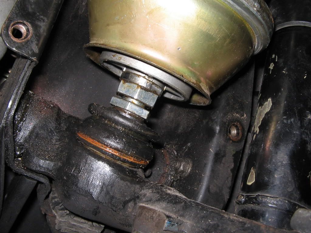
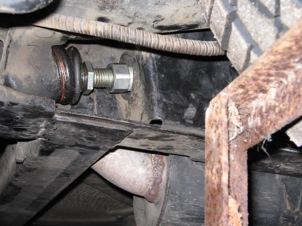
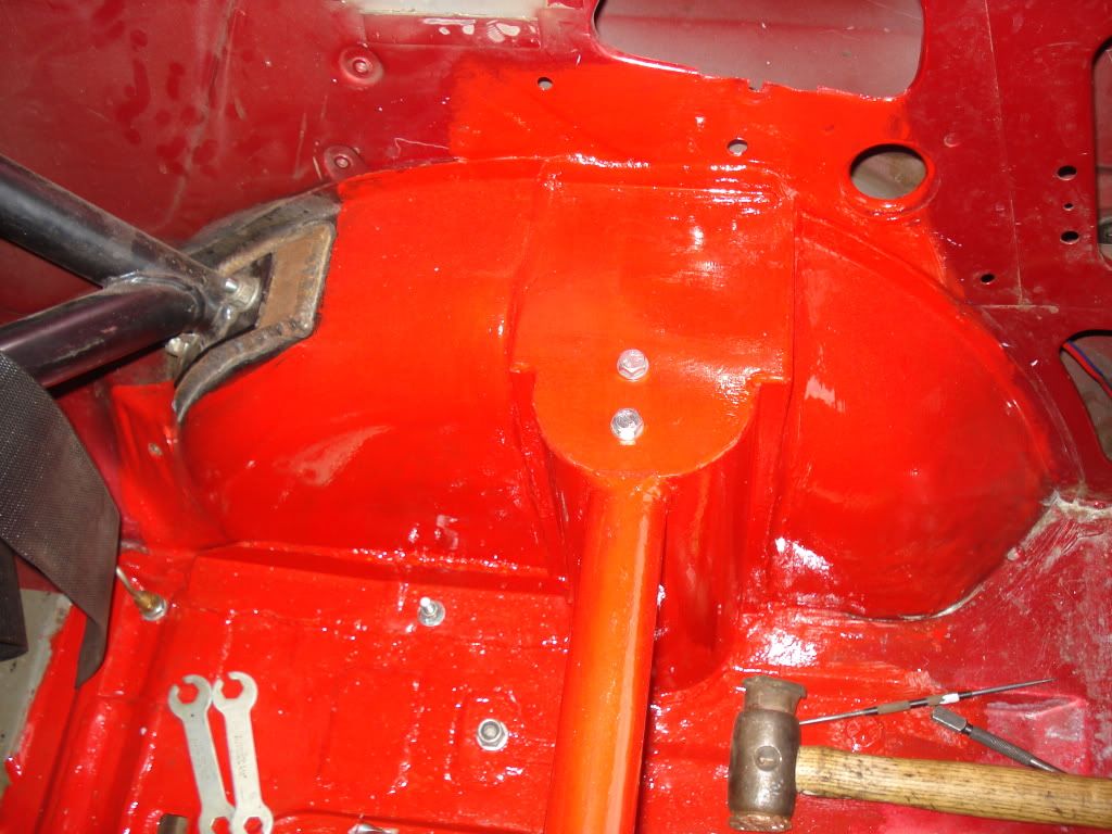
After setting up the camber and tracking, I could fit the rear dampers. To do this I needed to fabricate a bracket. I’m not a fan of stem mounts on dampers, so I’d had spherical bearings fitted. Unfortunately this meant a mounting bracket was required. I made the bracket out of angle, plate and nuts. It looks a little ugly, but it does the job.
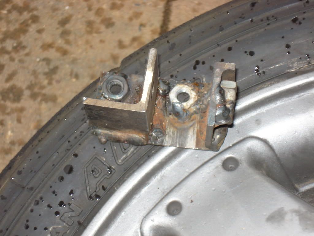
The bracket then just bolted into the turret.
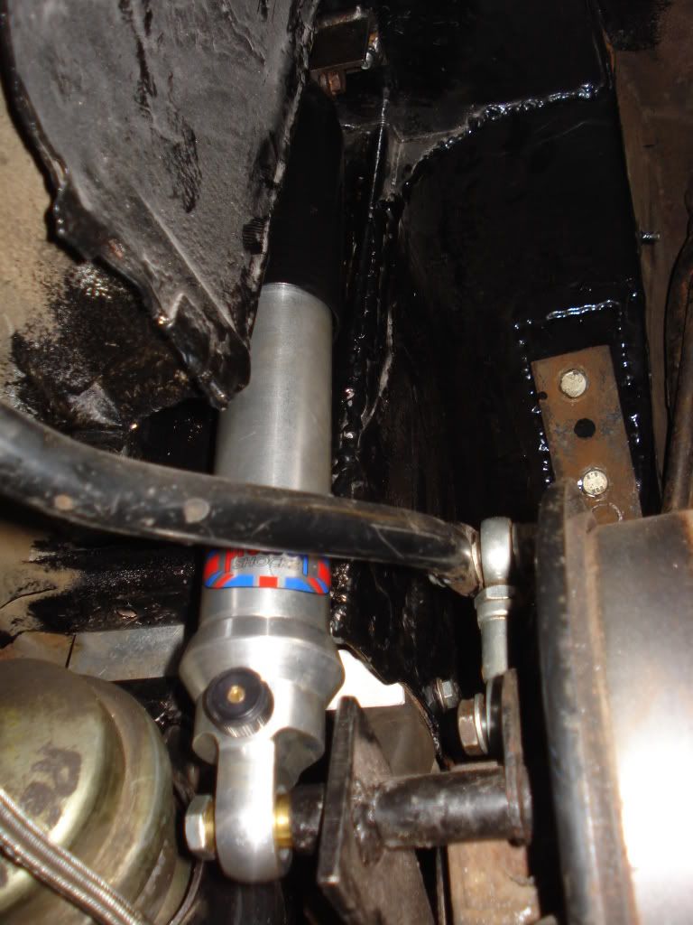
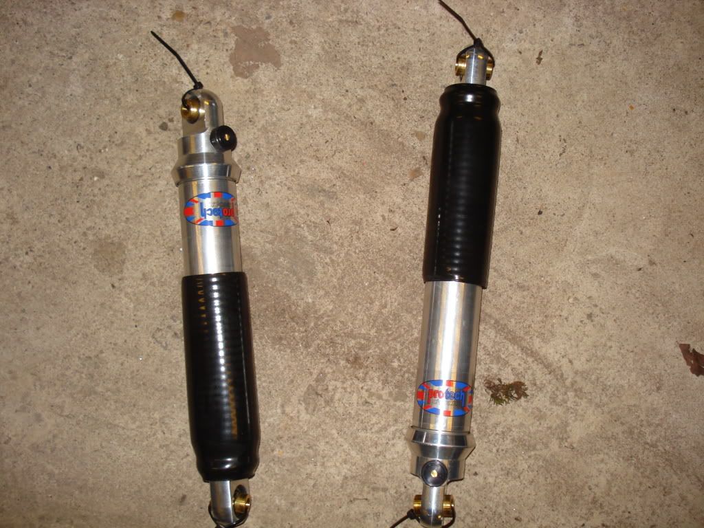
The Protech dampers are different to the Gaz or Spax people usually fit. They’ve a good reputation, and being alloy, they should be a little lighter. I asked them to valve them to suit a race car with hydragas, and the bump and rebound seem much closer than the Gaz MGF dampers I’ve got on the front. According to the velocity curves provided with them, they’re closer to 4:1 compression to bump, which is ok for a road car, but not as good for a race car. Hopefully the damping will be right, as I didn’t really want to have to fork out for the double adjustable ones.
Jim.
The front end of the car needs some attention. I had previously set up the bump steer, which was quite far off as standard, and even worse after my geometry was altered. To try and improve the setup, I got some converted spherical bearings that could be mounted much closer to the steering arm, hopefully allowing me to improve the bump steer around the new lower ride height. To get these to fit, I needed the steering arms drilling to fit the bolts, rather than the standard tapered part. As the holes needed to be a nice tight fit, I decided to get some help to do this, rather than attack them with a handheld drill, and some blunt drill bits. The bearings would naturally raise the steering arms up about 10mm higher than the standard rod end, which would help greatly with the bump steer. The steering rods had effectively been lowered when I increased the caster. When I tried it out with my home made bump steer gauge, the arms themselves only needed raising slightly with a couple of washers, rather than the 15mm worth of spacers I’d had fitted before. The upshot of this is that the bump steer is minimised at the normal suspension ride height. I’m not sure If there’s enough space to get a wheel weight past the steering arms, but hopefully I’ll always get these fitted on the outside of the rims anyway. They’re always a bit of a problem due to the tight clearance between wheel and caliper. This is especially true if your wheels are buckled!
The suspension setup for this year will be quite different from last year. I think I got the front / rear balance of roll stiffness wrong. Due to the different regs in class C, I can drop the nose, and run rear dampers. In addition, I have also acquired a corner weight gauge, which should help the setup. I need to add nearly 40kg of ballast, which should help the balance. I quickly got sick of taking the hydragas apart to swap the rods, or washers to set the ride height. This is the standard method of changing ride heights, and it’s pretty time consuming as the suspensions got to be depressurised and taken apart before being put back together and pumped up. This was the cue for some more tinkering. I designed a set of rods that would fit into the existing suspension, but had M16 bolts incorporated into them. This gave me the ability to jack the suspension up, and alter the ride heights in a fraction of the time. The front’s easier than the back, as there’s more space. I really need to cut a spanner down to make it quicker and easier at the back end. This mod’s really helpful to help me to corner weight the car. I’d already modified my pump so I could pump two hydragas spheres up at once, which gave me the ability to balance pressures, and therefore loads on an axle. After setting the ride heights I, had a test go with the gauge. The fronts both showed equal at 745 PSI, as did the rears at 525PSI. I was slightly surprised, but this made sense, as the ride heights all showed slightly different. It was something I’d considered when I’d modified my pump with the dual connection, but I’d never proved it till now.
After setting up the camber and tracking, I could fit the rear dampers. To do this I needed to fabricate a bracket. I’m not a fan of stem mounts on dampers, so I’d had spherical bearings fitted. Unfortunately this meant a mounting bracket was required. I made the bracket out of angle, plate and nuts. It looks a little ugly, but it does the job.
The bracket then just bolted into the turret.
The Protech dampers are different to the Gaz or Spax people usually fit. They’ve a good reputation, and being alloy, they should be a little lighter. I asked them to valve them to suit a race car with hydragas, and the bump and rebound seem much closer than the Gaz MGF dampers I’ve got on the front. According to the velocity curves provided with them, they’re closer to 4:1 compression to bump, which is ok for a road car, but not as good for a race car. Hopefully the damping will be right, as I didn’t really want to have to fork out for the double adjustable ones.
Jim.
Another update.
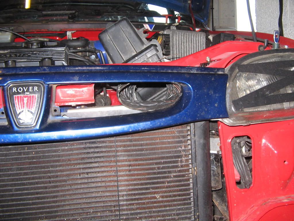
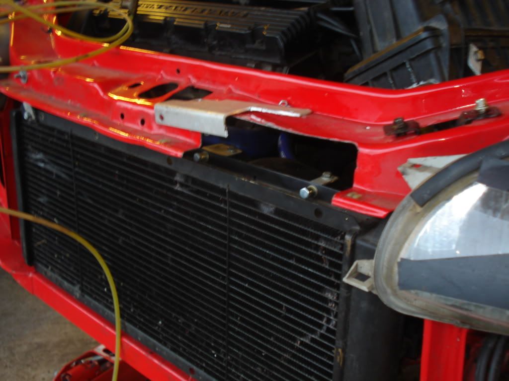
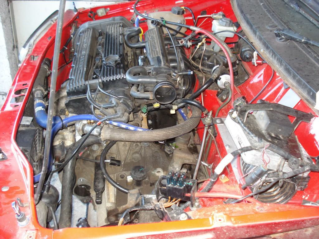
Whilst I had the front bumper off (I’d swapped the alternator earlier), I took the opportunity to improve the air inlet. The Rover 100 grill has removable kidney plates, which give a good location to run the inlet to. By cutting some metal away, and modifying the airbox, I made a pretty direct entry to the airbox. The fan bracket was causing a slight restriction, so I modified this into small brackets, which improved matters further. I could really do with making a scoop, so all the kidney area is used, but this will have to wait for some other time. You can see in the picture how big the bracket was originally, as I’ve left the remnants on the scuttle. The smaller ones are much fiddlier to fit though.
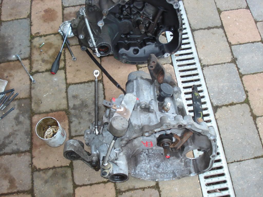
I had managed to acquire a R211 8V gearbox with the prized 4.2 diff ratio. I had been told they were like the proverbial rocking horse droppings, but I found one at my first attempt on Ebay. Guess I was just lucky. I managed to disconnect the gearbox and get it off the car without too much effort.
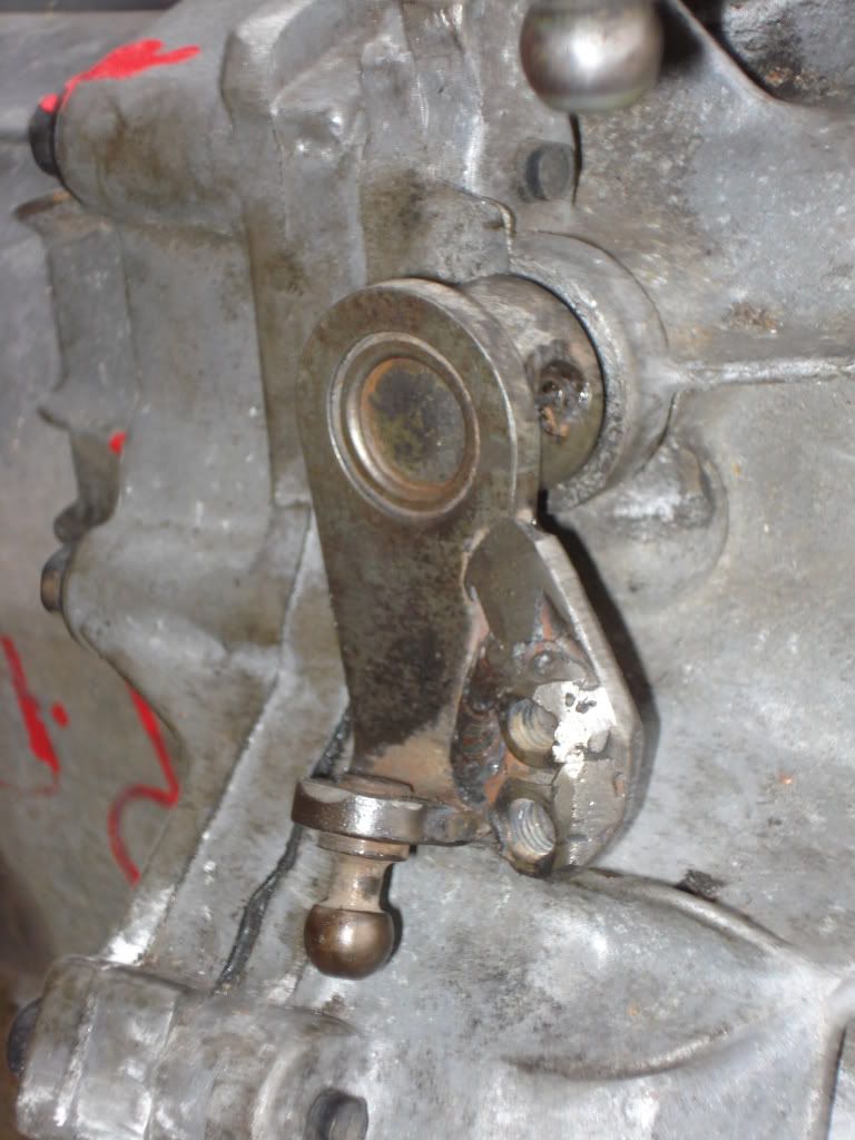
Once I’d done this I could swap over the mounting brackets from my old box onto the new. I’d heard the Rover 200 versions of the R65 had a different selector arm, and it clashed with the metro bulkhead. As this looked true, I cut the offending metal off.

After a bad experience at Rockingham, I’d converted my gear linkage away from balls and cups to proper rose joints that wouldn’t just come apart because they felt like it. This meant I simply needed to weld a new metal strip on in the appropriate place. I’d originally used M5 joints, with stud bar in between. This proved to be a little weak, with the lower selector bending, hence the temporary repair with some hefty sized stud bar that was lying around.
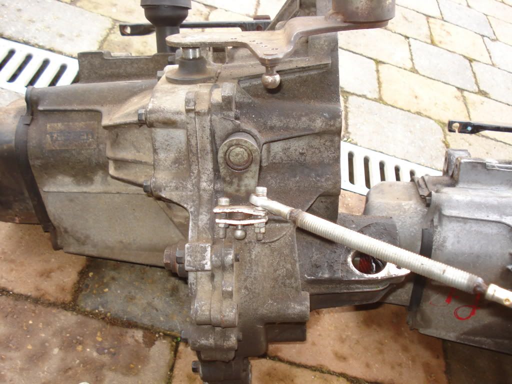
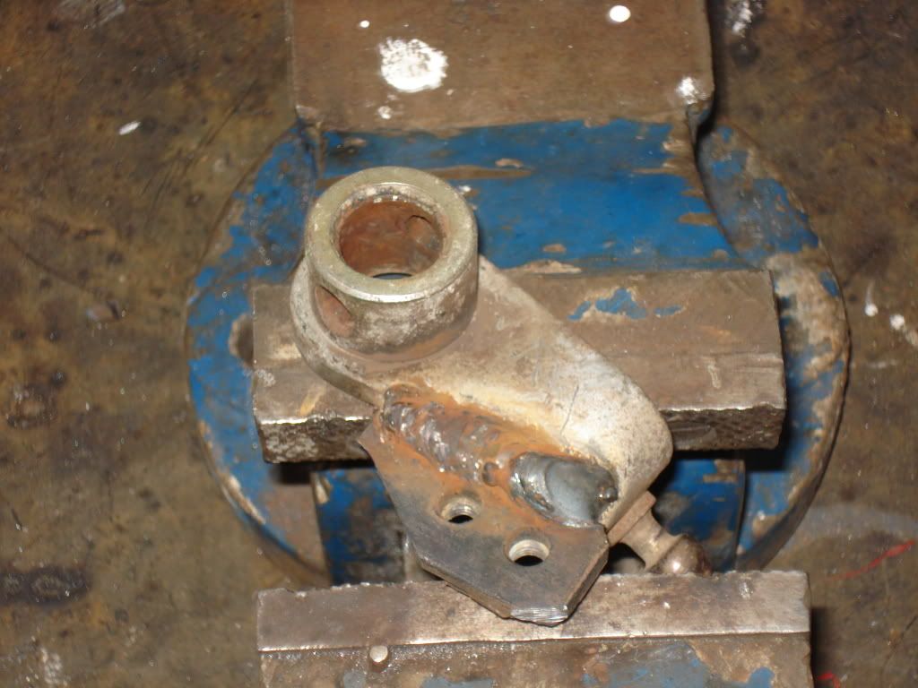
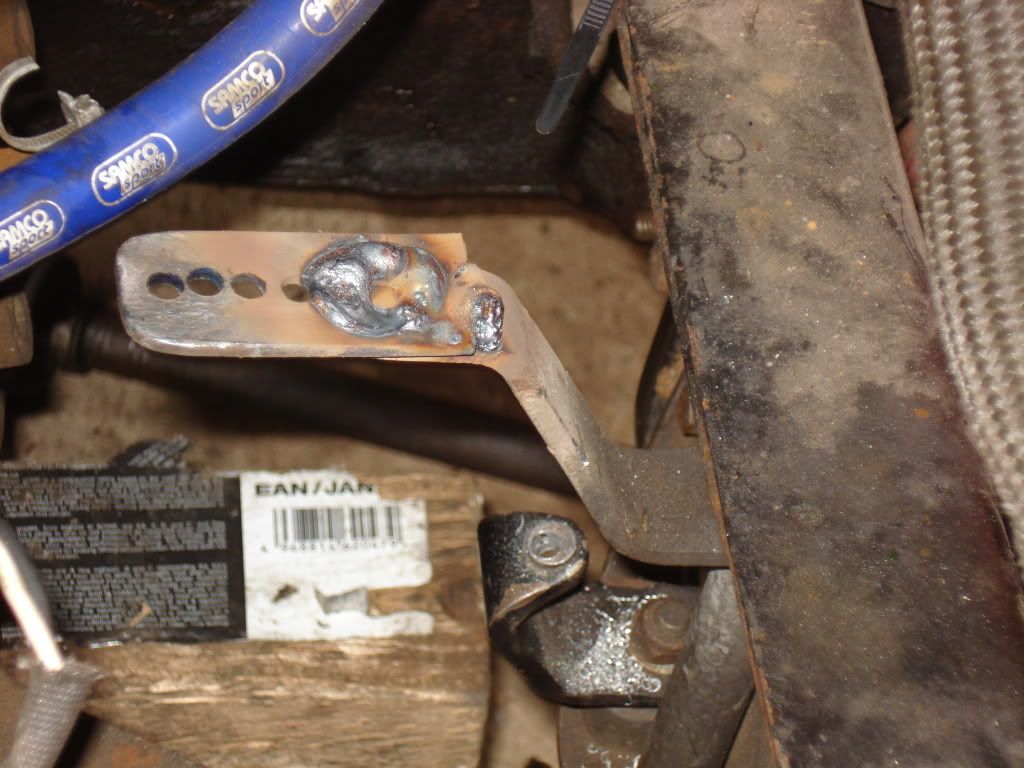
I’d upgraded to M6 rose joints, with proper turnbuckles. Hopefully the extra stiffness should help the shift quality. When I’d done the conversion, the gearbox had been in the car, and I didn’t have very good access to the lower selector. I’d made a bracket that bolted on, which despite looking rubbish, did the job. As I had the box out, I thought I’d do something better. After a couple of minutes of head scratching, I welded a couple of nuts onto some plate, then welded this onto the selector arm.
The cross gate shift was either really slack or really tight before, depending on whether the linkage was on top, or below the bracket. The new position should be in the middle. There is a slacker second position in case, and I can space the other end with washers to tighten the throw. After some finishing I think it turned out ok. The feel with the gearbox in the car’s ok, just need to test it in anger now.
I also took the chance to weld an extension to the linkage that had previously been bolted on. This extension acts as a quick shift, but unfortunately it had come loose at Snetterton during the four hour relay. Despite the poor access, I think it’s properly attached now.
As one of my mates was having trouble getting hold of a decent engine loom, I offered to make one for him. After a quick bit of research it didn’t seem too hard….so I didn’t think it would take too long. The engine loom is built around Tyco (AMP) Econoseal connectors, junior timer plugs and conventional 6.35 / 9.35mm blade connections. I thought I could save myself some hassle by going to one place for all the parts, as hopefully they’d save me the hassle of doing all the research. It was a good plan, but it just didn’t work out. In the end I found a really useful page on the Tyco website that was linked to the distributors, so that you could choose a part, then go straight to the relevant page on the net, usually RS or Farnell. I found just about everything I needed this way. The wire also caused me some headaches. It had been my original intention to copy the loom exactly, and so I’d tried to get all the correct colours. There’s just so many that not all of them are off the shelf, and when you’re only after a few meters nobody will pay to do a run for you. I ended up with half the loom coloured, and half black. In retrospect I should have done it all in two or three colours, as most of it’s not visible anyway. Having a really good drawing showing the circuits and the plug references is just as good when fault finding, and a new loom should last quite a while before it has any faults.
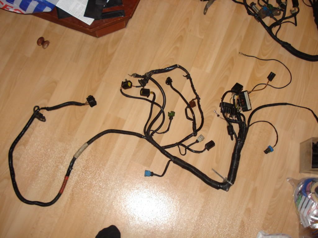
I used the loom from my car as a guide, in the belief that it was original, and would work with any car. After using the Rover 100 factory wiring diagrams, which aren’t quite the same as my loom, and the Haynes manual, I came up with what should have been the correct loom. Unfortunately the loom in Tom’s car wasn’t the same as mine. It had been converted from single point injection to multi point injection, which would have been ok, if it had been done well…..which it hadn’t. After installing the loom, and repairing the faults on the existing body loom, the car started and ran ok. I’d installed switches as back ups for the relay’s at Tom’s request. Connecting these in was tricky, as I needed a larger crimp then I had access to. I used terminal strip in the end, but wasn’t really satisfied. I’m going to make him another one for his other race car, so I might use proper terminal block with ring crimps, should make for a better job.
Jim.
Whilst I had the front bumper off (I’d swapped the alternator earlier), I took the opportunity to improve the air inlet. The Rover 100 grill has removable kidney plates, which give a good location to run the inlet to. By cutting some metal away, and modifying the airbox, I made a pretty direct entry to the airbox. The fan bracket was causing a slight restriction, so I modified this into small brackets, which improved matters further. I could really do with making a scoop, so all the kidney area is used, but this will have to wait for some other time. You can see in the picture how big the bracket was originally, as I’ve left the remnants on the scuttle. The smaller ones are much fiddlier to fit though.
I had managed to acquire a R211 8V gearbox with the prized 4.2 diff ratio. I had been told they were like the proverbial rocking horse droppings, but I found one at my first attempt on Ebay. Guess I was just lucky. I managed to disconnect the gearbox and get it off the car without too much effort.
Once I’d done this I could swap over the mounting brackets from my old box onto the new. I’d heard the Rover 200 versions of the R65 had a different selector arm, and it clashed with the metro bulkhead. As this looked true, I cut the offending metal off.
After a bad experience at Rockingham, I’d converted my gear linkage away from balls and cups to proper rose joints that wouldn’t just come apart because they felt like it. This meant I simply needed to weld a new metal strip on in the appropriate place. I’d originally used M5 joints, with stud bar in between. This proved to be a little weak, with the lower selector bending, hence the temporary repair with some hefty sized stud bar that was lying around.
I’d upgraded to M6 rose joints, with proper turnbuckles. Hopefully the extra stiffness should help the shift quality. When I’d done the conversion, the gearbox had been in the car, and I didn’t have very good access to the lower selector. I’d made a bracket that bolted on, which despite looking rubbish, did the job. As I had the box out, I thought I’d do something better. After a couple of minutes of head scratching, I welded a couple of nuts onto some plate, then welded this onto the selector arm.
The cross gate shift was either really slack or really tight before, depending on whether the linkage was on top, or below the bracket. The new position should be in the middle. There is a slacker second position in case, and I can space the other end with washers to tighten the throw. After some finishing I think it turned out ok. The feel with the gearbox in the car’s ok, just need to test it in anger now.
I also took the chance to weld an extension to the linkage that had previously been bolted on. This extension acts as a quick shift, but unfortunately it had come loose at Snetterton during the four hour relay. Despite the poor access, I think it’s properly attached now.
As one of my mates was having trouble getting hold of a decent engine loom, I offered to make one for him. After a quick bit of research it didn’t seem too hard….so I didn’t think it would take too long. The engine loom is built around Tyco (AMP) Econoseal connectors, junior timer plugs and conventional 6.35 / 9.35mm blade connections. I thought I could save myself some hassle by going to one place for all the parts, as hopefully they’d save me the hassle of doing all the research. It was a good plan, but it just didn’t work out. In the end I found a really useful page on the Tyco website that was linked to the distributors, so that you could choose a part, then go straight to the relevant page on the net, usually RS or Farnell. I found just about everything I needed this way. The wire also caused me some headaches. It had been my original intention to copy the loom exactly, and so I’d tried to get all the correct colours. There’s just so many that not all of them are off the shelf, and when you’re only after a few meters nobody will pay to do a run for you. I ended up with half the loom coloured, and half black. In retrospect I should have done it all in two or three colours, as most of it’s not visible anyway. Having a really good drawing showing the circuits and the plug references is just as good when fault finding, and a new loom should last quite a while before it has any faults.
I used the loom from my car as a guide, in the belief that it was original, and would work with any car. After using the Rover 100 factory wiring diagrams, which aren’t quite the same as my loom, and the Haynes manual, I came up with what should have been the correct loom. Unfortunately the loom in Tom’s car wasn’t the same as mine. It had been converted from single point injection to multi point injection, which would have been ok, if it had been done well…..which it hadn’t. After installing the loom, and repairing the faults on the existing body loom, the car started and ran ok. I’d installed switches as back ups for the relay’s at Tom’s request. Connecting these in was tricky, as I needed a larger crimp then I had access to. I used terminal strip in the end, but wasn’t really satisfied. I’m going to make him another one for his other race car, so I might use proper terminal block with ring crimps, should make for a better job.
Jim.
After finishing off quite a few little jobs, I was ready for a shakedown test. Being local(ish) I chose Cadwell. Things started off pretty well, despite the rain. Nothing fell off, and the car felt ok. The biggest issue was a soft brake pedal. It took a while to get rid of the winter rust, then I started to get into my groove. There were only a few cars there, so the track was pretty clear, and the slow cars were easy to clear. The difference of running A048’s over A539’s was immense. The 48’s don’t go off after a lap, so the front end keeps it’s grip. The car feels transformed with them.
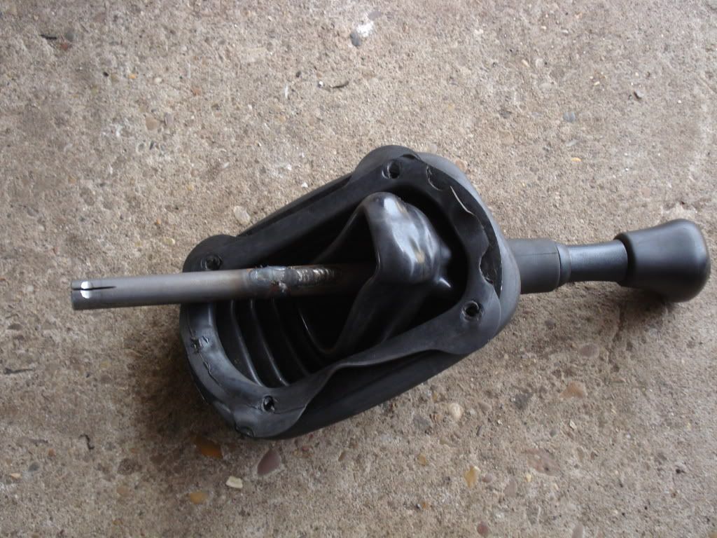
Class C allows a 4.2 diff. I’d have preferred either retaining the 3.7, or using the 3.9 from a rover 214, as these are both easily available. I definitely like the 4.2 though, I can see why people say it’s just right for the car. The gearchange felt really tight, no doubt helped the new linkage, and lack of track abuse. I had to use a standard gear lever, which felt a little short, so I need to improve that. One of my mates had a VX220 one going spare, but despite spending a couple of hours searching he couldn’t find it. I therefore had to extend the standard lever. I added about 100mm, which has brought the lever a lot closer to the wheel.
The ratio’s feel nice and close, helping to mask some of the gaps in the gearing. I can also accelerate in fifth now! I got a few comments about how well it went, and the usual surprise when I tell people it’s only a 1400, and no the headgaskets not gone yet! I lost a bit of time after shearing a bleed nipple off one of the rear cylinders. Luckily I had another cylinder in my box of bits, but it was a pain to change. In the end I just got used to having nothing for the first inch of travel, could still lock the brakes up, so the powers there. I can sort that out before Donnington anyway.
I’ve linked a video of me doing a lap below.
http://www.youtube.com/watch?v=8CRXoLLTwww&fea...
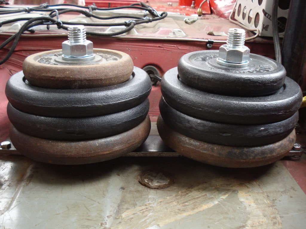
To hit the 865kg car and driver weight I’ve had to add some ballast. Given the cost of lead, I used some weights that I had lying about. I made a frame with some M24 bolts, and 5mm thick plate.
The first race of the seasons at Donington, on the 8th, so hopefully everything’s ready!
Jim.
Class C allows a 4.2 diff. I’d have preferred either retaining the 3.7, or using the 3.9 from a rover 214, as these are both easily available. I definitely like the 4.2 though, I can see why people say it’s just right for the car. The gearchange felt really tight, no doubt helped the new linkage, and lack of track abuse. I had to use a standard gear lever, which felt a little short, so I need to improve that. One of my mates had a VX220 one going spare, but despite spending a couple of hours searching he couldn’t find it. I therefore had to extend the standard lever. I added about 100mm, which has brought the lever a lot closer to the wheel.
The ratio’s feel nice and close, helping to mask some of the gaps in the gearing. I can also accelerate in fifth now! I got a few comments about how well it went, and the usual surprise when I tell people it’s only a 1400, and no the headgaskets not gone yet! I lost a bit of time after shearing a bleed nipple off one of the rear cylinders. Luckily I had another cylinder in my box of bits, but it was a pain to change. In the end I just got used to having nothing for the first inch of travel, could still lock the brakes up, so the powers there. I can sort that out before Donnington anyway.
I’ve linked a video of me doing a lap below.
http://www.youtube.com/watch?v=8CRXoLLTwww&fea...
To hit the 865kg car and driver weight I’ve had to add some ballast. Given the cost of lead, I used some weights that I had lying about. I made a frame with some M24 bolts, and 5mm thick plate.
The first race of the seasons at Donington, on the 8th, so hopefully everything’s ready!
Jim.
I can send the drawings if you want them, pdf or CAD? Can you send me a personal mail with your email address? I'm a bit gutted at the moment. Was at Donington yesterday, and it didn't go well at all. One lap of qualifying and the engine went bang. There had been an intermittent tick, which I was thought was a sticky tappet. It might actually have been the little end though....
Jim.
Jim.
Apologies for the major thread revival (now posting two years after the last post in this thread)!
Webbj2, I really like your solution to setting the corner weights on your Metro - and would like to do the same on my MGF. How have you found this solution in practice over the last two seasons? If you still have the technical schematics, I'd really like to try and replicate what you've done!
Great thread, thanks
gazz0788 said:
Hello all, brilliant work, im currently doing the same to my 94' GTa. This mite be a stab in the dark but any chance you could send me a pdf or info on your hydragas setup, as that looks a easier way of adjustment for corner wieghting.thanks
If you need the details, let me know - I am sure Jim won't mind me passing the info on I've no problem with you passing on the details. The interesting thing if you're corner weighting is to modify your hydragas pump so that you can pump up both sides at once. The weights are balanced hydraulically, so you get even weights consistently side to side without any real effort. Even if you want to work diagonally it's a good starting point and idea, as you can fit ball valves to either side and save yourself some time, and fluid.
Jim.
Jim.
Gassing Station | Readers' Cars | Top of Page | What's New | My Stuff