SEAT Ibiza - rwd turbo
Discussion


I'm just in the middle of building a custom trailer to carry the car, as it's a bit too wide for the std range of car trailers........... (well, the non "plant" ones that are nice to tow as the wheels are outside the bed area)
I'm also in the middle of revising the brake master cylinder and location and adding some plumbing and wiring so i can install my ABS system into the car in the near future ( ABS for competition cars )
I'm also in the middle of revising the brake master cylinder and location and adding some plumbing and wiring so i can install my ABS system into the car in the near future ( ABS for competition cars )
Been hacking along with some little jobs on the car:
1st up, as the rest of the car is now running using CAN databuses, i needed a module to "translate" for my old Motec engine ecu, which only speaks Australian (not really, it's Rs232 actually). So this little silver box (sitting in front of M8 ecu) parses in engine data via a RS232 dataline, validates it, and then spits it out onto the Primary Powertrain CAN databus, meaning it is available for the OBL (OnBoardLogger) and all the other control modules (Throttles, Transmission, Bodymodule, Map module, FuelPump module etc):

Next up is the start of work on a "smart" handwheel. Again, modernising the instrumentation and HMI, this is the start of the patterns for a carbon fiber handwheel, with integrated instrumentation and input capability (again, over CAN to minimise the looming requirement):
Starts with a pattern formed to the shape of the carbon "structure" of the wheel:
Front:

Rear:

Specific moulds have been made to form an ergonomic and "grippy" shape to the parts of the wheel that will be held, and used to make silicon "grips":

Front of wheel will have a drop in carbon panel that houses the PCB and display/switchgear etc:

Top of rim has gear selection indicator, and "shift light" strip, centre with configurable display (type TBC, probably some sort of graphic OLED), input selectors for various systems, and some buttons/warning lights etc
Finally, work has started on a new rear wing, more in keeping with the cars styling:

That^^ is just the original wing on a set of bodged up brackets to position it in an aerodynamically decent position (luckily, no regs to worry about anymore to meet "silhouette" or wing height/area etc). Next step is to mock up side mounting brackets to locate it and act as guide channels for the airflow.
Currently wondering about some WRC inspired design, perhaps like the latest PoloR one?
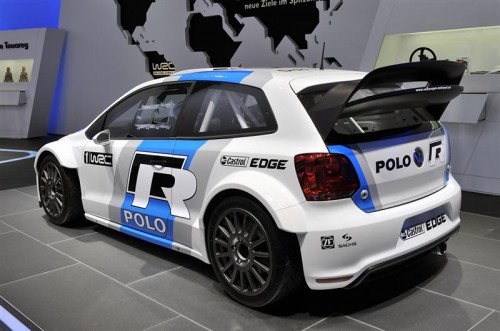
Suggestions anyone?? ;-)
1st up, as the rest of the car is now running using CAN databuses, i needed a module to "translate" for my old Motec engine ecu, which only speaks Australian (not really, it's Rs232 actually). So this little silver box (sitting in front of M8 ecu) parses in engine data via a RS232 dataline, validates it, and then spits it out onto the Primary Powertrain CAN databus, meaning it is available for the OBL (OnBoardLogger) and all the other control modules (Throttles, Transmission, Bodymodule, Map module, FuelPump module etc):
Next up is the start of work on a "smart" handwheel. Again, modernising the instrumentation and HMI, this is the start of the patterns for a carbon fiber handwheel, with integrated instrumentation and input capability (again, over CAN to minimise the looming requirement):
Starts with a pattern formed to the shape of the carbon "structure" of the wheel:
Front:
Rear:
Specific moulds have been made to form an ergonomic and "grippy" shape to the parts of the wheel that will be held, and used to make silicon "grips":
Front of wheel will have a drop in carbon panel that houses the PCB and display/switchgear etc:
Top of rim has gear selection indicator, and "shift light" strip, centre with configurable display (type TBC, probably some sort of graphic OLED), input selectors for various systems, and some buttons/warning lights etc
Finally, work has started on a new rear wing, more in keeping with the cars styling:
That^^ is just the original wing on a set of bodged up brackets to position it in an aerodynamically decent position (luckily, no regs to worry about anymore to meet "silhouette" or wing height/area etc). Next step is to mock up side mounting brackets to locate it and act as guide channels for the airflow.
Currently wondering about some WRC inspired design, perhaps like the latest PoloR one?
Suggestions anyone?? ;-)
Edited by anonymous-user on Friday 25th April 15:54
Fastdruid said:
Nice! How are you doing the connection to the wheel? I'm doing similar and running mine through a clockspring and a mini plug in the centre of the quick release.
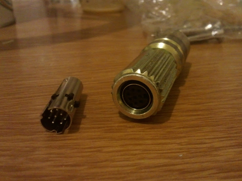
The quick release has to align well before the engagement on the socket so should always line up.
Currently with just a "coiled" cable (a-la old skool telephone handset!) Sinple and works well as i only have 1.4 turns lock2lock. I might move to a Lemo connector in the middle of the spline coupler, or possibly to some "pogo" pins and a target in the middle. Only 4 wires (12v, gnd, CANH, CANL) and could move to "power over CAN" and drop that to 2 wires if necessary.The quick release has to align well before the engagement on the socket so should always line up.
mwstewart said:
Awesome work as always. I'd love to spend a weekend watching you work, just to learn loads of things if nothing else!
Polo spoiler looks good.
Do it. If the two of you started building a car together it would be the most amazingly amazing high-quality thing ever. It'd never get finished of course but it'd be a hell of an everlasting build thread.Polo spoiler looks good.
rohrl said:
mwstewart said:
Awesome work as always. I'd love to spend a weekend watching you work, just to learn loads of things if nothing else!
Polo spoiler looks good.
Do it. If the two of you started building a car together it would be the most amazingly amazing high-quality thing ever. It'd never get finished of course but it'd be a hell of an everlasting build thread.Polo spoiler looks good.
Right time to break out the MDF!
First cut some trial end plates / supports to try to get an idea for what it looks like and the form factor required to support the wing element(s) in 3 axes:
Vertical square end plates close to elements to linearise airflow and prevent overspill at the ends:

Currently, the main upper element is really a bit too wide (by about 100mm), but i'm loath to cut it down for two reasons (more area = more downforce and it's a rather nice ex BTCC carbon element.... ;-)

The "Pukka" WRC cars have to have the wing system completely hidden (when viewed from the front) within the frontal area of the car (hence all the wacky complex shaped rear wings you see) but i don't! As the rear screen slope of my Ibiza is steep, the wing system will have to be quite high and rearwards to work effectively without being in the "shadow" of the cabin/roof. Sticking out the sides so to speak will make a large difference, as the ends of the element will be in cleaner air. Of course, the effecive AOA of the aerofoil section will change across it's width, but for now, without a wind tunnel or a lot of CFD we will have to manage as is! Luckily, with almost no rear overhang (rear wheels are right at the back of the car, even more so than normal as i lengthened the wheelbase by 50mm)my car is relatively non coupled in terms of front/rear aero balance, with the rear device acting pretty much straight down onto the rear wheels.
I would like to packaged a second, lower and adjustable / removable aerofoil element below the main upper element, and upright ends plates should allow that:

The issue so far is going to be getting a nice looking blend into the supports as they need to curve in to meet the tailgate frame. Hmmm? Hoping for some inspiration here as how to make that look nice without messing up the airflow stream lines!
First cut some trial end plates / supports to try to get an idea for what it looks like and the form factor required to support the wing element(s) in 3 axes:
Vertical square end plates close to elements to linearise airflow and prevent overspill at the ends:
Currently, the main upper element is really a bit too wide (by about 100mm), but i'm loath to cut it down for two reasons (more area = more downforce and it's a rather nice ex BTCC carbon element.... ;-)
The "Pukka" WRC cars have to have the wing system completely hidden (when viewed from the front) within the frontal area of the car (hence all the wacky complex shaped rear wings you see) but i don't! As the rear screen slope of my Ibiza is steep, the wing system will have to be quite high and rearwards to work effectively without being in the "shadow" of the cabin/roof. Sticking out the sides so to speak will make a large difference, as the ends of the element will be in cleaner air. Of course, the effecive AOA of the aerofoil section will change across it's width, but for now, without a wind tunnel or a lot of CFD we will have to manage as is! Luckily, with almost no rear overhang (rear wheels are right at the back of the car, even more so than normal as i lengthened the wheelbase by 50mm)my car is relatively non coupled in terms of front/rear aero balance, with the rear device acting pretty much straight down onto the rear wheels.
I would like to packaged a second, lower and adjustable / removable aerofoil element below the main upper element, and upright ends plates should allow that:
The issue so far is going to be getting a nice looking blend into the supports as they need to curve in to meet the tailgate frame. Hmmm? Hoping for some inspiration here as how to make that look nice without messing up the airflow stream lines!
 tmental. I love it!
Gassing Station | Readers' Cars | Top of Page | What's New | My Stuff