SEAT Ibiza - rwd turbo
Discussion


Just for you then Tom, here's some engine pics!
Block built up with custom crank, after internal and external machining to loose mass, remove any flashing and stress raising sharp radii etc:

Bed plate and billet main bearing caps:

CNC'd "sump" (it's only 20mm deep) fitted over to further re-enforce bottom end:

Dry sump pump(later upgraded to extra scaveneg stage just for the turbo, due to low mounting height)

Custom super long T&K Precision head studs for uniform head/block clamp loading:

On with his head: ;-)

Mock up block/head installed to sort out carbon plenum, throttle system, and general plumbing etc:
[URL=http://s135.photobucket.com/user/max_torque_2006/media/SEAT%20Ibiza%20rally%20car/run4_zps25a45198.jpg.html]
 [/URL]


hmm, which sized turbo shall i use?

Yup, big one it is........ ;-)
You can get an idea for how far back the engine is fitted in the chassis from this pic:

Built engine waiting fitting:

Block built up with custom crank, after internal and external machining to loose mass, remove any flashing and stress raising sharp radii etc:

Bed plate and billet main bearing caps:

CNC'd "sump" (it's only 20mm deep) fitted over to further re-enforce bottom end:

Dry sump pump(later upgraded to extra scaveneg stage just for the turbo, due to low mounting height)

Custom super long T&K Precision head studs for uniform head/block clamp loading:

On with his head: ;-)

Mock up block/head installed to sort out carbon plenum, throttle system, and general plumbing etc:
[URL=http://s135.photobucket.com/user/max_torque_2006/media/SEAT%20Ibiza%20rally%20car/run4_zps25a45198.jpg.html]
[/URL]

hmm, which sized turbo shall i use?

Yup, big one it is........ ;-)
You can get an idea for how far back the engine is fitted in the chassis from this pic:

Built engine waiting fitting:


aww999 said:
Amazing stuff, which nicely illustrates the gulf between the home enthusiast and and experienced professional when it comes to doing stuff with cars. Normally I look at a build thread and think "I could do that if I had the same budget" but this is way beyond anything I could attempt. Two questions, if I may:
You say you measure the manifold pressure only on the intake stroke - what benefit does this give?
Also, how do you go about insuring something like this? I know it's not road legal but I have heard stories of project cars being stolen from garages etc.
Anyway, thanks for taking the time to walk us all through it and putting all these pictures online!
If you run with port throttles, you don't have the volume of the intake manifold to "average" out the intake pressure pulses. With a conventional single throttle into a large manifold volume and the into the individual runners, as the intake valve opens and the piston pulls air into chamber, the volume of the manifold damps out most of the fast pressure fluctuations, and the throttle ends up flowing a fairly constant mass flow rate. This means you can use Manifold Absolute Pressure (MAP) as engine load determination.You say you measure the manifold pressure only on the intake stroke - what benefit does this give?
Also, how do you go about insuring something like this? I know it's not road legal but I have heard stories of project cars being stolen from garages etc.
Anyway, thanks for taking the time to walk us all through it and putting all these pictures online!
However, what REALLY matters is the air charge density (or the amount of air) trapped in the cylinder when the intake valve closes, because this affects how much fuel you must add, and when you start that charge burning (ignition angle)
If you fit individual throttle plates to your engine (1 per cylinder/runner), there is not enough volume between those plates and the intake valve to damp the pressure fluctuations. Remember, that an intake stroke only occurs every 180degCA, so for the other ~3/4 of the time, the intake valve is shut, and the air in the runner stagnates.
At this point, most people move to using throttle angle as their load arbitor, but although this gives good response, it is poor in terms of absolute accuracy and repeatability, as tiny changes in pressures, air density, throttle angles and flow characteristics make big changes in the actual charge density at IVC (Inlet Valve Closure). And with a turbo car, where intake density and temperature, and crucially pre-turbine exhaust pressure can vary enormously, it's even harder to make it work properly.
To get round this, i developed a system that has a high bandwidth (able to respond very fast) MAP sensor fitted to each intake runner downstream of the individual throttle plates. By using the engine position sensors (Cam/crank sensor etc) my system can then sample each of those MAP sensors in the correct order, and only during the time the intake valve is open. As this "ignores" the pressure in the runners for the rest of the time, the signal to noise ratio is excellent, and the system reports a highly accurate charge density value per runner. This means you get a good, stable load determination, with excellent noise rejection and repeat ability.
Insurance is not an issue, plenty of companies are used to insuring unique classic and motorsport cars ;-)
Edited by anonymous-user on Sunday 27th October 11:49
Dry sump systems have 4 primary benefits:
1) They maintain a more consistent and reliable oil pressure feed under high g maneuvers. In a conventional sump, the oil is much freer to "slosh" around, especially due to the proximity of the spinning bottom end components. A dry sump tank, which is deliberately "tall and thin" rather than "wide and shallow" will keep the pressure pump well fed with oil at all times
2) The help to reduce oil consumption and can increase engine power. As there isn't a large volume of oil in the actual sump, windage (oil sloshing into the spinning crank etc) losses are reduced. Using multiple scavange pumps means oil can be drained from specific locations (like the cylinder head, or turbo etc) menaing less chance of large volumes of oil getting "hung up" in the corners of the engine. Less windage also means less oil vapour/mist, and lower losses of lubrication oil via "carryover" in the blowby gas extraction. A dry sump system can also be used to reduce the crank case pressure below atmospheric, again reducing parastic windage losses.
3) Generally, the lower profile dry sump means the installed height of the powertrain can be reduced. This lowers the vehicles CofG to the benefit of maximum lateral / longitudinal grip.
4) Removing the oil from the main crankcase results in much improved oil cooling, and more efficient separation of the blowby gases from the oil.
A dry sump system also has several deficits. They tend to be heavier than a conventional system, and the drive system (normally a toothed belt) can be vulnerable to damage
Part 23a - Cooling systems:
With the engine pushed back behind the front axle for reasons of polar moment and static mass distribution, that left lots of space for the cooling pack to be optimised (and the steering rack to sit across the car in the optimum location for zero bump steer too, v. unusual in a front engined car).
A lightweight tubular frame carries the intercooler and main cooling radiator, and provides location for the plastic ducts and guide partitions to help channel the air efficiently into the rads.
Both IC and main rad are custom cores with ally end caps. Particular attention was paid to the flow geometry of the IC end caps (none of that nasty square tank/stubby pipe sticking out rubbish):

Wiggins couplings are used for the IC pipework connections:


Fan pack for main rad sits in carbon molded support to ensure high fan efficiency (important for a rally car that spends a lot of time going sideways (poor dynamic ramming) at a relatively low vehicle speed:

Rad & IC in place:

Kevlar underguard also forms lower air channel for main radiator inlet:

I decided to keep the original "crash bar" across the front (with some lightening) as rally cars tend to seek out rather solid objects to hit.......

The original steel bonnet was cut about and used to make a plug for a mold used to make a carbon/kevlar replacement with large exit vent for the rad pack:

Trial fit of bonnet test part made out of glass fibre to check trimming and clearances:

Just about enough room to tuck the ITG carbon air box under the front offside chassis rail:

Shiny plumbing, and oil-water heat exchanger mounted in 'top hose':

neiljohnson said:
Awesome but just one question
Isn't the air box a bit low for a rally car?? Surely going through water would result in hydro locking the engine!
Don't worry, i've thought of that! The air box sits in a "box" formed by the front bumper, inner wings, and the sump guard/undertray. Air gets rammed into this volume by the vehicles forward velocity and decellerates resulting in a nice high pressure feed for the airbox. However, the actual inlet for the airbox is mounted forwards of the inlet scoop outlet. As such, air must stop, and flow backwards into the airbox. That alone makes water ingestion unlikely, as the high density of water means it is "unwilling" to be turned 180deg due to it's momentum. Of course, a situation (like a crossing a ford etc) could lead to the entire volume being filled with water. To avoid this, there is a rubber "flap" fitted across the back of the volume in the inner wheelwell, that can be pushed open by the momentum of any water that enters that volume. (exit area is 3x entry area). As such, water arriving at high speed simply continues straight on through and out into the undertray/inner wing area. Of course, being stationary in deep water (over approx 10" deep) would be bad in this case as the airbox would be completely submerged. So best avoid that then ;-)Isn't the air box a bit low for a rally car?? Surely going through water would result in hydro locking the engine!
neiljohnson said:
Max_Torque said:
Don't worry, i've thought of that
Why am I not surprised you have come up with a way to avoid the water getting in but........You could have just mounted it higher

1) no room to do so (without compromising on the IC pipework and routing)
2) It would raise the cars CofG
3) It would result in a more tortuous intake path to the compressor
4) The current location is optimum for pressure recovery
;-)
Deadgrau5 said:
Please may I ask what is your profession? If you are not in engineering you really really should be!
Funnily enough i work in the automotive business! I've been lucky enough to work for a lot of the major OEM's and specialist consultancies, and chances are, a lot of the cars driven by people on PH include my engineering in them. One day i really must put together a list of all the cars i have ever worked on, but it would be quite a long list!DanSaff said:
Cheers 
It was and I have re read the thread again and it you mentioned it when asked about the camber change on the strut and then followed on to say about the rally cars.
I was hoping for a bit of cheeky info as I wouldn't say struggling but more undecided on which setup to go with.
on searching around I have found since my posting that double wishbones suffer from scrub on compression, and since I'm wanting to drag race it on a Sunday and track it on the Wednesday it might not be the way to go.
Anyway top class car!!
You can of course set up a double wishbone architecture to practically reproduce any other suspension system, including reducing scrub to effectively zero.It was and I have re read the thread again and it you mentioned it when asked about the camber change on the strut and then followed on to say about the rally cars.
I was hoping for a bit of cheeky info as I wouldn't say struggling but more undecided on which setup to go with.
on searching around I have found since my posting that double wishbones suffer from scrub on compression, and since I'm wanting to drag race it on a Sunday and track it on the Wednesday it might not be the way to go.
Anyway top class car!!
You have to weight up the advantages and disadvantages of each suspension system and make a judgement call. There is no single "right" answer, just a different set of compromises.
Depending on the actual vehicle in question, simple details such as the type and details of the body structure may make a certain type of suspension system impractical. And it's worth noting, the more complicated and adjustable you make a system the more "wrong" ways there are or setting it up!
Struts in a saloon car makes sense, as long as the lateral g limit is going to be below about 1.5g (i.e. no seriously aero assisted cars). Struts are very tall and so simply can't be sensibly packaged in a single seater for example.
My gearbox is the old Quaife 'HD' sequential, rated to 750Nm iirc. It's tough, but a bit clunky and really quite heavy. Swapping to pneumatic paddle shifting means i don't notice the clunkiness now, but i'd love to loose 15kg off the weight of the transmission. As a lot of people find, these days your transmission is more limiting that your engine. With modern EMS, finding 500hp/nm isn't actually too hard, but installing a reliable transmission to leverage that power to the ground is a lot harder (and mucho £££!)
Just completed a couple of minor "avionics" updates to enable the future installation of my prototype Antilock Brake and stability system. Initally just for logging chassis data and refining my realtime dynamics model.
Steering Angle Sensor swapped for a higher resolution absolute position sensor on the base of the steering column:

Bosch combined YAW rate & Lat/Long accelerometer (CAN output) installed on chassis CofG:

Bandpass audio spectrum amplifier for the next dyno sesion so i can log some Knock Sensor data:

ABS hydraulic modulator reverse engineering ongoing:

Currently, for rig test i have just removed the orginal OTP microcontroller from the ABS unit, and control the solenoid driver ASIC over SPi (which i "sniff hacked" before removing the original uC). I have a vehicle model running at 1kHz on a STM32F4 micro and another of the same micro controlling the ABS solenoids/pump. I plan to build a HIL test rig next, and that should enable me to run full vehicle sims with the actual test hardware etc. I have done some basic sim work in Simulink, but as i am not autocoding, the actual test code is in raw C.
The STM32F4 is a massive overkill really (32b >200MHz with h/w ALU/FPP etc) but means i don't have to worry too much about execution latency etc
The STM32F4 is a massive overkill really (32b >200MHz with h/w ALU/FPP etc) but means i don't have to worry too much about execution latency etc
DaveJH said:
Max_Torque said:
Currently, for rig test i have just removed the orginal OTP microcontroller from the ABS unit, and control the solenoid driver ASIC over SPi (which i "sniff hacked" before removing the original uC). I have a vehicle model running at 1kHz on a STM32F4 micro and another of the same micro controlling the ABS solenoids/pump. I plan to build a HIL test rig next, and that should enable me to run full vehicle sims with the actual test hardware etc. I have done some basic sim work in Simulink, but as i am not autocoding, the actual test code is in raw C.
The STM32F4 is a massive overkill really (32b >200MHz with h/w ALU/FPP etc) but means i don't have to worry too much about execution latency etc
Is there an English version of this for us mere mortals? The STM32F4 is a massive overkill really (32b >200MHz with h/w ALU/FPP etc) but means i don't have to worry too much about execution latency etc

Luckily the ABS unit i am using has a separate Application Specific Integrated Circuit (ASIC) that directly controls the electromechanical solenoids used to modify brake system hydraulic pressure. That ASIC is commanded over an industry standard serial communications bus using the SPi protocol. That mean't i could "eavesdrop" on the commands sent by the std microcontroller and work out how the solenoid control ASIC was commanded.
Replacing the original microcontroller(which i can't modify) with a modern 32bit ARM microcontroller meant i can play around with various control strategies and modify how the device operates.
In order to test how the device works, i have "built" a vehicle dynamics model that runs in real time on a second high speed ARM micro, and this means i can optimise the various input/output & control stragegies before i get anywhere near a real car (which is obviously a good idea when you're mucking around with brakes!)
The next step is to include the actual brake hardware in a Hardware In Loop (HIL) test. This uses the real mechanical parts, such as a brake master cyclinder, ABS modulator, and even brake calipers to assess how the entire system works before installing it in my car.
Simples
Trickiest bit?
Getting the transmission integration and control correct! Getting repeatable, fast, non damaging shifts across the complete range of road speed and engine torques is very tricky when you have a pretty basic EMS controlling the fuel and spark. Particularly the timing and shape of the torque interruption event and the actuator pressure preload on the shift system at that point. It's still not very good tbh.!
Getting the transmission integration and control correct! Getting repeatable, fast, non damaging shifts across the complete range of road speed and engine torques is very tricky when you have a pretty basic EMS controlling the fuel and spark. Particularly the timing and shape of the torque interruption event and the actuator pressure preload on the shift system at that point. It's still not very good tbh.!

I'm just in the middle of building a custom trailer to carry the car, as it's a bit too wide for the std range of car trailers........... (well, the non "plant" ones that are nice to tow as the wheels are outside the bed area)
I'm also in the middle of revising the brake master cylinder and location and adding some plumbing and wiring so i can install my ABS system into the car in the near future ( ABS for competition cars )
I'm also in the middle of revising the brake master cylinder and location and adding some plumbing and wiring so i can install my ABS system into the car in the near future ( ABS for competition cars )
Been hacking along with some little jobs on the car:
1st up, as the rest of the car is now running using CAN databuses, i needed a module to "translate" for my old Motec engine ecu, which only speaks Australian (not really, it's Rs232 actually). So this little silver box (sitting in front of M8 ecu) parses in engine data via a RS232 dataline, validates it, and then spits it out onto the Primary Powertrain CAN databus, meaning it is available for the OBL (OnBoardLogger) and all the other control modules (Throttles, Transmission, Bodymodule, Map module, FuelPump module etc):

Next up is the start of work on a "smart" handwheel. Again, modernising the instrumentation and HMI, this is the start of the patterns for a carbon fiber handwheel, with integrated instrumentation and input capability (again, over CAN to minimise the looming requirement):
Starts with a pattern formed to the shape of the carbon "structure" of the wheel:
Front:

Rear:

Specific moulds have been made to form an ergonomic and "grippy" shape to the parts of the wheel that will be held, and used to make silicon "grips":

Front of wheel will have a drop in carbon panel that houses the PCB and display/switchgear etc:

Top of rim has gear selection indicator, and "shift light" strip, centre with configurable display (type TBC, probably some sort of graphic OLED), input selectors for various systems, and some buttons/warning lights etc
Finally, work has started on a new rear wing, more in keeping with the cars styling:

That^^ is just the original wing on a set of bodged up brackets to position it in an aerodynamically decent position (luckily, no regs to worry about anymore to meet "silhouette" or wing height/area etc). Next step is to mock up side mounting brackets to locate it and act as guide channels for the airflow.
Currently wondering about some WRC inspired design, perhaps like the latest PoloR one?
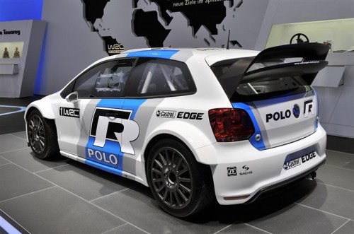
Suggestions anyone?? ;-)
1st up, as the rest of the car is now running using CAN databuses, i needed a module to "translate" for my old Motec engine ecu, which only speaks Australian (not really, it's Rs232 actually). So this little silver box (sitting in front of M8 ecu) parses in engine data via a RS232 dataline, validates it, and then spits it out onto the Primary Powertrain CAN databus, meaning it is available for the OBL (OnBoardLogger) and all the other control modules (Throttles, Transmission, Bodymodule, Map module, FuelPump module etc):
Next up is the start of work on a "smart" handwheel. Again, modernising the instrumentation and HMI, this is the start of the patterns for a carbon fiber handwheel, with integrated instrumentation and input capability (again, over CAN to minimise the looming requirement):
Starts with a pattern formed to the shape of the carbon "structure" of the wheel:
Front:
Rear:
Specific moulds have been made to form an ergonomic and "grippy" shape to the parts of the wheel that will be held, and used to make silicon "grips":
Front of wheel will have a drop in carbon panel that houses the PCB and display/switchgear etc:
Top of rim has gear selection indicator, and "shift light" strip, centre with configurable display (type TBC, probably some sort of graphic OLED), input selectors for various systems, and some buttons/warning lights etc
Finally, work has started on a new rear wing, more in keeping with the cars styling:
That^^ is just the original wing on a set of bodged up brackets to position it in an aerodynamically decent position (luckily, no regs to worry about anymore to meet "silhouette" or wing height/area etc). Next step is to mock up side mounting brackets to locate it and act as guide channels for the airflow.
Currently wondering about some WRC inspired design, perhaps like the latest PoloR one?
Suggestions anyone?? ;-)
Edited by anonymous-user on Friday 25th April 15:54
Fastdruid said:
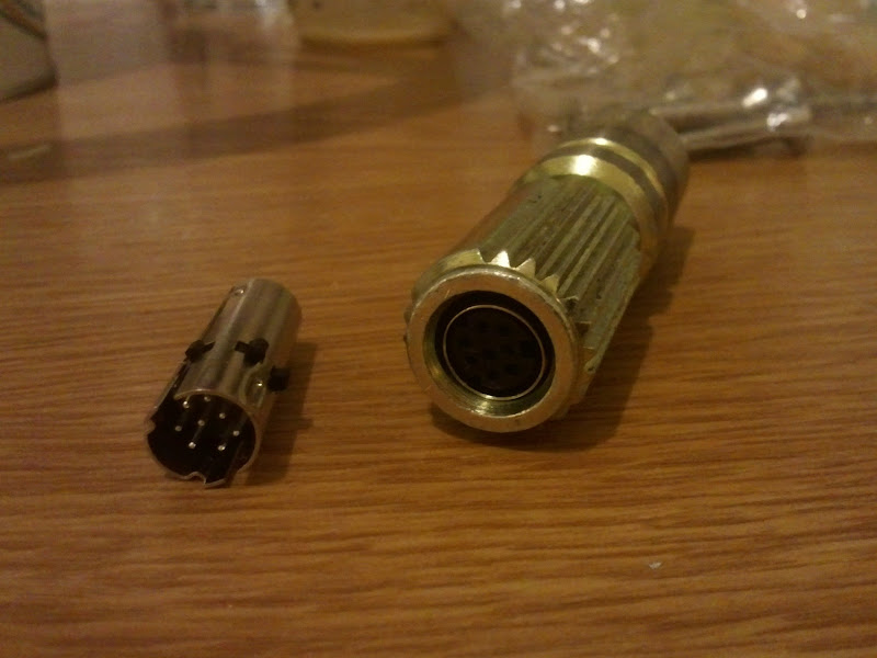
Nice! How are you doing the connection to the wheel? I'm doing similar and running mine through a clockspring and a mini plug in the centre of the quick release.
The quick release has to align well before the engagement on the socket so should always line up.
Currently with just a "coiled" cable (a-la old skool telephone handset!) Sinple and works well as i only have 1.4 turns lock2lock. I might move to a Lemo connector in the middle of the spline coupler, or possibly to some "pogo" pins and a target in the middle. Only 4 wires (12v, gnd, CANH, CANL) and could move to "power over CAN" and drop that to 2 wires if necessary.The quick release has to align well before the engagement on the socket so should always line up.
Gassing Station | Readers' Cars | Top of Page | What's New | My Stuff