Celica ST205 GT4 - Phase 2!
Discussion


August 11th 2013
Bit of an update today, I got brave!
First off though, I finally managed to set up my garage PC
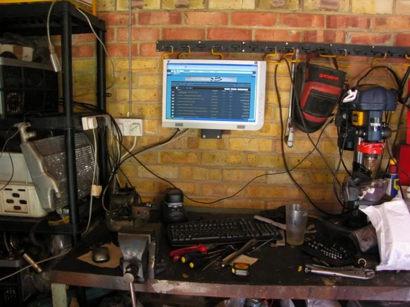
So I now spend a lot less time running in and out, and it is safer than having the laptop on my workbench
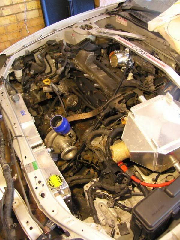
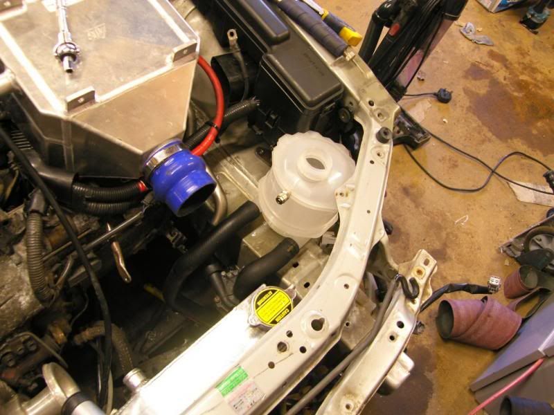
Now for the brave bit, as you know I have been a bit tight on space for the cooling pack and I also want to replace the front cross member. The solution to my problems? Get choppy
These are the normal pressings that surround the rad / headlight assembly -
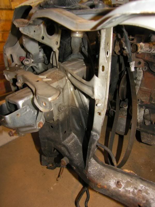
I used the spot weld drill, a pry bar and the angle grinder detach the pressings

A little bit of hacksaw action to some places inaccessible to the angle grinder
And it all came off -
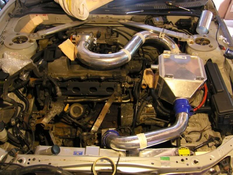
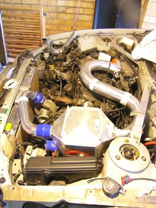
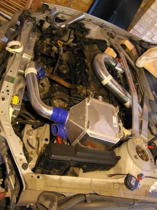
After a bit of tidying with the flap disc -
Rinse and repeat for the other side and then try the rads for size
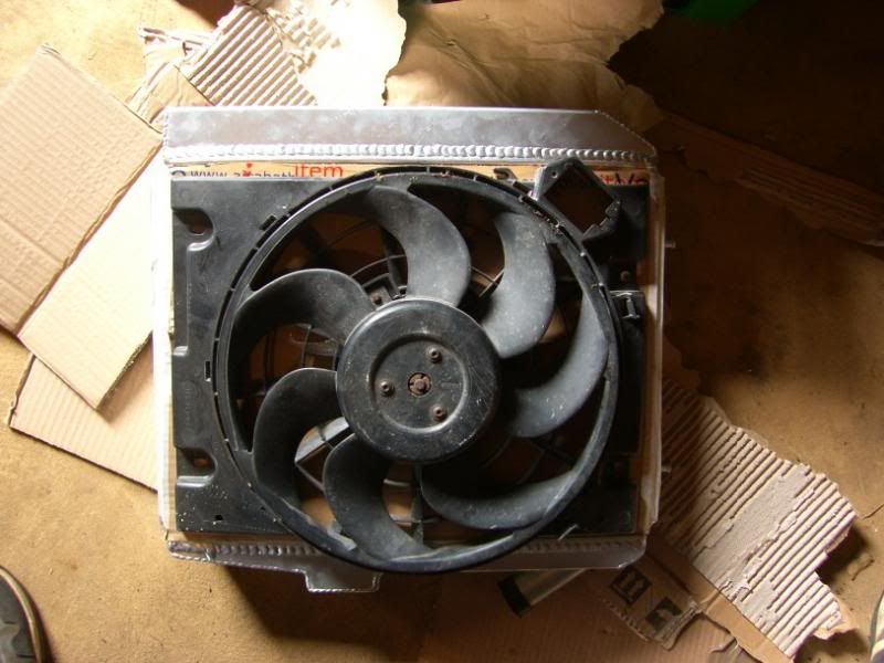
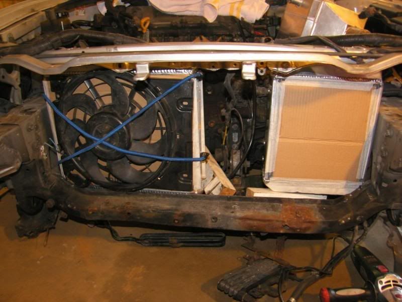
I started to think about fans and placing of the rads, I want them to be as far back as possible but still have a fan. After a bit of rooting around in the garage I found the pusher fan I used on the supercharged imp, put it on the rad and it was perfect!
Even fits well in the front of the car!
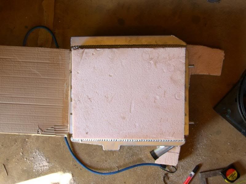
I then decided to start making up a mould for slightly better fitting fan cowl, out came the insulation foam! -
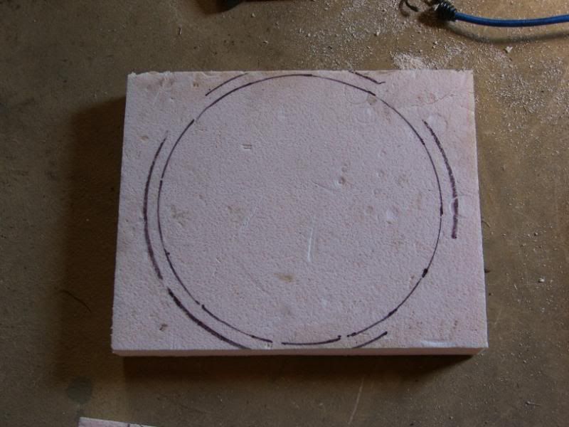
The fan traced onto the surface -
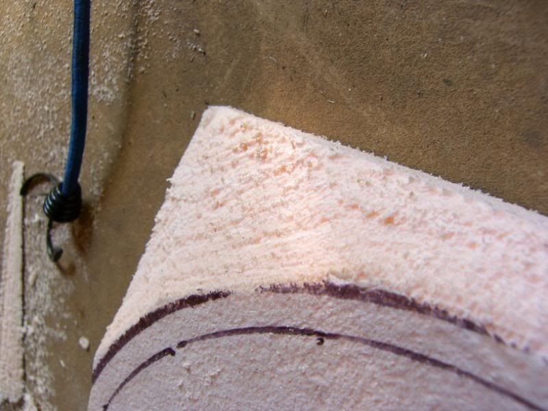
Rough cut -
Some sanding -
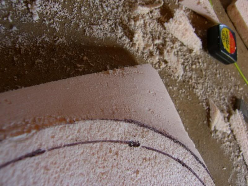
And there she is! -
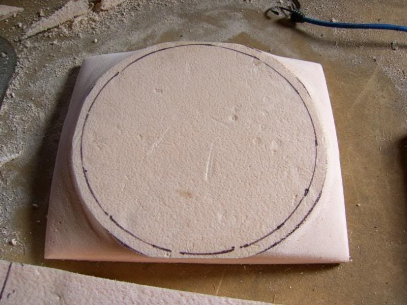
This will be covered in release agent and then laid up with epoxy and glass then carbon for the top skin
I have all the bits to make the exhaust manifold on their way, so that should be our next installment
Thats it for now, more soon!
J
Bit of an update today, I got brave!
First off though, I finally managed to set up my garage PC
So I now spend a lot less time running in and out, and it is safer than having the laptop on my workbench
Now for the brave bit, as you know I have been a bit tight on space for the cooling pack and I also want to replace the front cross member. The solution to my problems? Get choppy
These are the normal pressings that surround the rad / headlight assembly -
I used the spot weld drill, a pry bar and the angle grinder detach the pressings
A little bit of hacksaw action to some places inaccessible to the angle grinder
And it all came off -
After a bit of tidying with the flap disc -
Rinse and repeat for the other side and then try the rads for size
I started to think about fans and placing of the rads, I want them to be as far back as possible but still have a fan. After a bit of rooting around in the garage I found the pusher fan I used on the supercharged imp, put it on the rad and it was perfect!
Even fits well in the front of the car!
I then decided to start making up a mould for slightly better fitting fan cowl, out came the insulation foam! -
The fan traced onto the surface -
Rough cut -
Some sanding -
And there she is! -
This will be covered in release agent and then laid up with epoxy and glass then carbon for the top skin
I have all the bits to make the exhaust manifold on their way, so that should be our next installment
Thats it for now, more soon!
J
August 13th 2013
Another little update
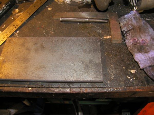
Today a little package that weighed a lot arrived, it contained......steel!
A big bit of 80mm x 10mm x 600mm for the head flange and a piece 200mm x 100mm x 10mm for the turbo flanges.
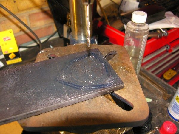
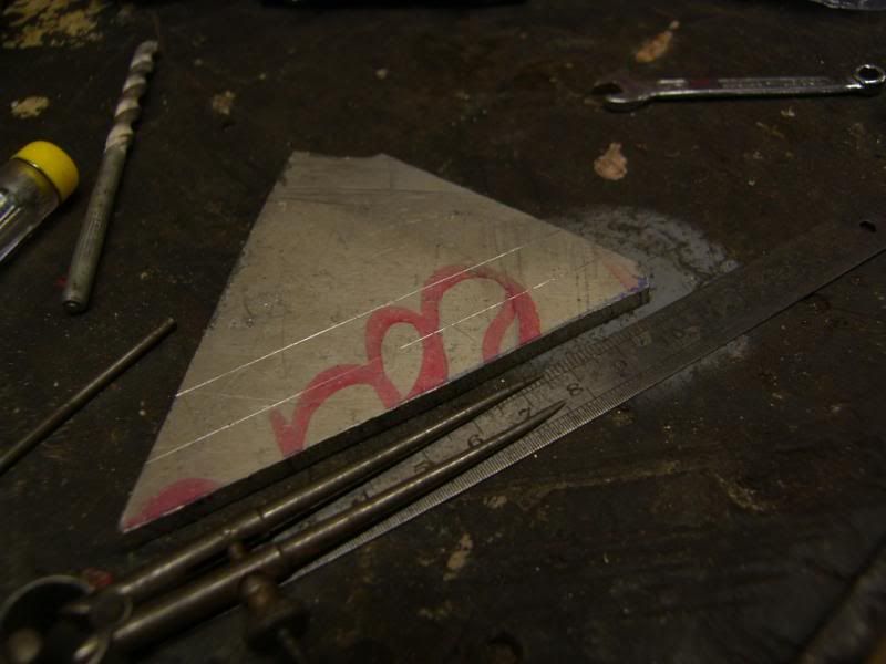
I made a start straight away, marking out the turbine inlet flange -
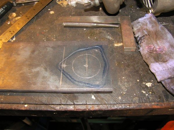
Pilot holes drilled -
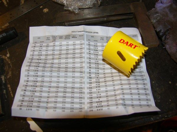
I calculated the tip speed for the hole saw, 20m/s for mild steel, the RPM calculation is -
20m/s * 1000 / 45mm * Pi = 141rpm
Then I realised there was a speed table in the box with the saw!
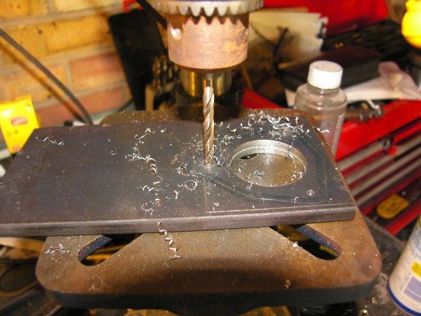
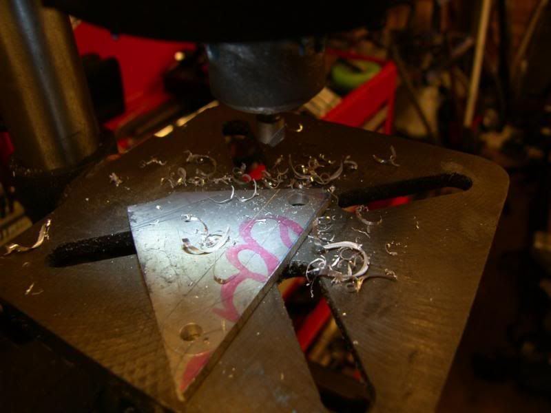
I then got my wife to help me by spraying coolant over the hole saw, keeping the teeth cool and helping it cut properly. I then enlarged the bolt holes to size too -
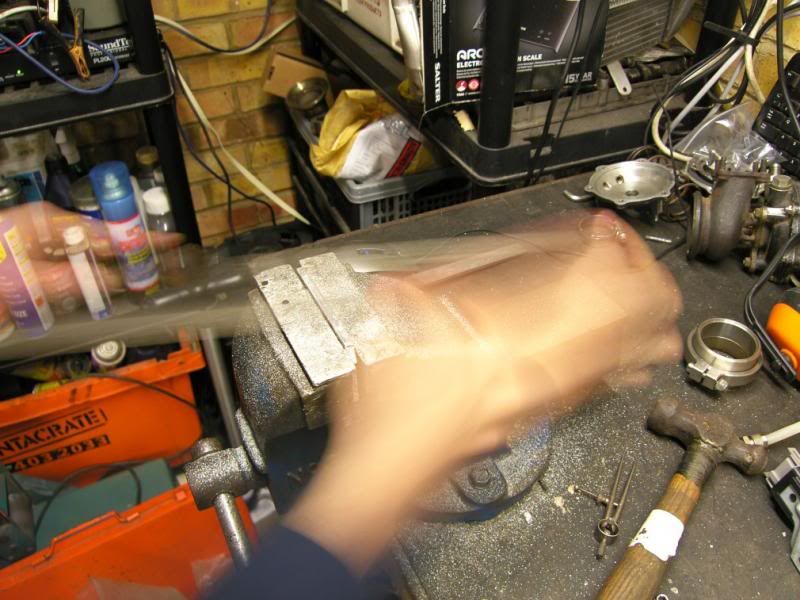
Next I rough cut the flange out using the angle grinder and a 1.2mm cutting disc. In the past I would have done this with a hacksaw, just didn't fancy it today
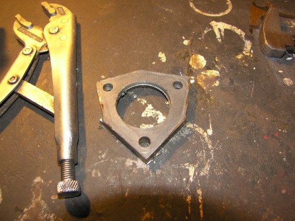
And then set to work on the belt linisher, this is a slow process as my linisher is pretty weak, but I am getting there. I stopped at this point for dinner, and will finish it tomorrow.
More tomorrow
J
Another little update
Today a little package that weighed a lot arrived, it contained......steel!
A big bit of 80mm x 10mm x 600mm for the head flange and a piece 200mm x 100mm x 10mm for the turbo flanges.
I made a start straight away, marking out the turbine inlet flange -
Pilot holes drilled -
I calculated the tip speed for the hole saw, 20m/s for mild steel, the RPM calculation is -
20m/s * 1000 / 45mm * Pi = 141rpm
Then I realised there was a speed table in the box with the saw!
I then got my wife to help me by spraying coolant over the hole saw, keeping the teeth cool and helping it cut properly. I then enlarged the bolt holes to size too -
Next I rough cut the flange out using the angle grinder and a 1.2mm cutting disc. In the past I would have done this with a hacksaw, just didn't fancy it today
And then set to work on the belt linisher, this is a slow process as my linisher is pretty weak, but I am getting there. I stopped at this point for dinner, and will finish it tomorrow.
More tomorrow
J
August 22nd 2013
Bit more progress chaps!
After a brilliant weekend at RRG, with the 1005bhp Short Sport Quattro and the 700bhp Sunbeam Talbot spurring me on, I was back in the garage like a rat up a drain pipe
I put a new belt onto the linisher and cracked on with the turbine inlet flange, the new belt munched through the steel like a badger on MDMA. The result is one of the best fits I have ever managed when hand fabricating, it is all very well being able to send a DXF file to a laser cutting place, but being able to do this by hand really does bring a smile to my face
[img src="http://i27.photobucket.com/albums/c186/twin_charged/Celica/SH105449_zpsb030c9a5.jpg" style="max-width:100%;"]
[img src="http://i27.photobucket.com/albums/c186/twin_charged/Celica/SH105448_zpse9d39a81.jpg" style="max-width:100%;"]
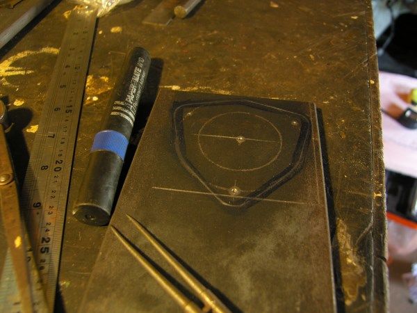
With the wind behind me the turbine outlet flange was marked out
[img src="http://i27.photobucket.com/albums/c186/twin_charged/Celica/SH105451_zps52e70dfc.jpg" style="max-width:100%;"]
Then pilot drilled and then three mounting holes drilled out size on size for the studs, this was being cocky as it would require the holes to be in exactly the right place for it to fit.
[img src="http://i27.photobucket.com/albums/c186/twin_charged/Celica/SH105452_zpsac2d7ff2.jpg" style="max-width:100%;"]
What d'ya know! *smug*
[img src="http://i27.photobucket.com/albums/c186/twin_charged/Celica/SH105453_zps7cf9e89c.jpg" style="max-width:100%;"]
[img src="http://i27.photobucket.com/albums/c186/twin_charged/Celica/SH105454_zps7c45baea.jpg" style="max-width:100%;"]
I then cracked out the 60mm hole saw, again a slow process with the drill geared as slow as it would go. To be honest my little pillar drill is a bit feeble for this task, but she soldiered through with plenty of WD40
[img src="http://i27.photobucket.com/albums/c186/twin_charged/Celica/SH105455_zpse5c58c8f.jpg" style="max-width:100%;"]
Then out with the 1.2mm slitting discs, time to make a mess!
[img src="http://i27.photobucket.com/albums/c186/twin_charged/Celica/SH105458_zpsc7c65765.jpg" style="max-width:100%;"]
Once roughed out, back to the linisher for shaping and final fit. The result I am rather pleased with, they fit bob on, the only down side being they make the turbine housing twice the weight!
[img src="http://i27.photobucket.com/albums/c186/twin_charged/Celica/SH105460_zpscb64c81b.jpg" style="max-width:100%;"]
[img src="http://i27.photobucket.com/albums/c186/twin_charged/Celica/SH105461_zps45cd5a89.jpg" style="max-width:100%;"]
Next up, the big one, exhaust head flange. Again in 10mm steel so we don't warp it when welding and with pre-turbine 1000 degree exhaust gas. I will be attacking that over the weekend.
The bends and *cheating* collector will be arriving very soon so it can all be mocked up ready for the TIG to be brought out
More soon chaps.
J
Bit more progress chaps!
After a brilliant weekend at RRG, with the 1005bhp Short Sport Quattro and the 700bhp Sunbeam Talbot spurring me on, I was back in the garage like a rat up a drain pipe
I put a new belt onto the linisher and cracked on with the turbine inlet flange, the new belt munched through the steel like a badger on MDMA. The result is one of the best fits I have ever managed when hand fabricating, it is all very well being able to send a DXF file to a laser cutting place, but being able to do this by hand really does bring a smile to my face
[img src="http://i27.photobucket.com/albums/c186/twin_charged/Celica/SH105449_zpsb030c9a5.jpg" style="max-width:100%;"]
[img src="http://i27.photobucket.com/albums/c186/twin_charged/Celica/SH105448_zpse9d39a81.jpg" style="max-width:100%;"]
With the wind behind me the turbine outlet flange was marked out
[img src="http://i27.photobucket.com/albums/c186/twin_charged/Celica/SH105451_zps52e70dfc.jpg" style="max-width:100%;"]
Then pilot drilled and then three mounting holes drilled out size on size for the studs, this was being cocky as it would require the holes to be in exactly the right place for it to fit.
[img src="http://i27.photobucket.com/albums/c186/twin_charged/Celica/SH105452_zpsac2d7ff2.jpg" style="max-width:100%;"]
What d'ya know! *smug*
[img src="http://i27.photobucket.com/albums/c186/twin_charged/Celica/SH105453_zps7cf9e89c.jpg" style="max-width:100%;"]
[img src="http://i27.photobucket.com/albums/c186/twin_charged/Celica/SH105454_zps7c45baea.jpg" style="max-width:100%;"]
I then cracked out the 60mm hole saw, again a slow process with the drill geared as slow as it would go. To be honest my little pillar drill is a bit feeble for this task, but she soldiered through with plenty of WD40
[img src="http://i27.photobucket.com/albums/c186/twin_charged/Celica/SH105455_zpse5c58c8f.jpg" style="max-width:100%;"]
Then out with the 1.2mm slitting discs, time to make a mess!
[img src="http://i27.photobucket.com/albums/c186/twin_charged/Celica/SH105458_zpsc7c65765.jpg" style="max-width:100%;"]
Once roughed out, back to the linisher for shaping and final fit. The result I am rather pleased with, they fit bob on, the only down side being they make the turbine housing twice the weight!
[img src="http://i27.photobucket.com/albums/c186/twin_charged/Celica/SH105460_zpscb64c81b.jpg" style="max-width:100%;"]
[img src="http://i27.photobucket.com/albums/c186/twin_charged/Celica/SH105461_zps45cd5a89.jpg" style="max-width:100%;"]
Next up, the big one, exhaust head flange. Again in 10mm steel so we don't warp it when welding and with pre-turbine 1000 degree exhaust gas. I will be attacking that over the weekend.
The bends and *cheating* collector will be arriving very soon so it can all be mocked up ready for the TIG to be brought out
More soon chaps.
J
August 26th 2013
Little update, finished all of the heavy metal work
The exhaust head flange was always going to be difficult, oval ports, many holes and just quite a big bit of steel
I started by marking it all out using the exhaust gasket as a guide, this was checked against the head and although the hole centers are in the right place, the holes are not the right size. This applies particularly to the ports, the gasket holes are +5mm in all dimensions, I guess to ensure clearance under all tolerance conditions. A restriction on one cylinder would be catastrophic under full load conditions, with increased exhaust gas temps and gas flow restrictions causing fueling imbalances and possible piston and head problems.
Anyway, they were marked out -
[img src="http://i27.photobucket.com/albums/c186/twin_charged/Celica/SH105462_zps01d68815.jpg" style="max-width:100%;"]
I don't have any pictures of the drilling, as it was tough going, the drill was untouchably hot by the time the holes were drilled, I was also occupied swatting wasps (got a queen so I am happy ).
Post drilling this is where we were -
[img src="http://i27.photobucket.com/albums/c186/twin_charged/Celica/SH105464_zpsb2dae822.jpg" style="max-width:100%;"]
I did start using a dremel but the shards of metal were so sharp that I stopped, pulled the swarf out of my hands and cracked out the hand file
[img src="http://i27.photobucket.com/albums/c186/twin_charged/Celica/SH105465_zpsc8eed2fd.jpg" style="max-width:100%;"]
The half round actually made short work of the material left, I got a good dab on and smashed through it all
I also took the opportunity to slot the holes, not to make it fit but to allow for heat expansion. The mild steel I have used is not as prone as stainless, but it is a good precaution to take at this stage, the last thing I want is snapped studs
[img src="http://i27.photobucket.com/albums/c186/twin_charged/Celica/SH105466_zps3c7041d5.jpg" style="max-width:100%;"]
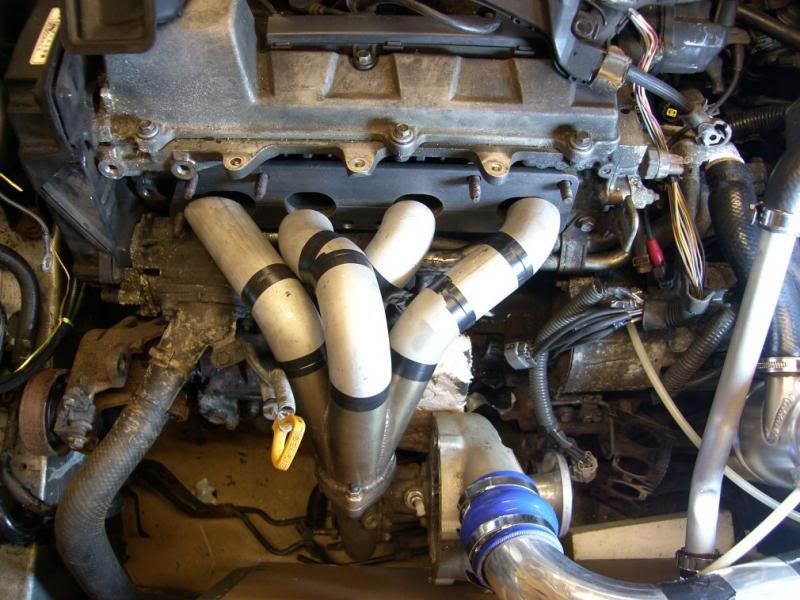
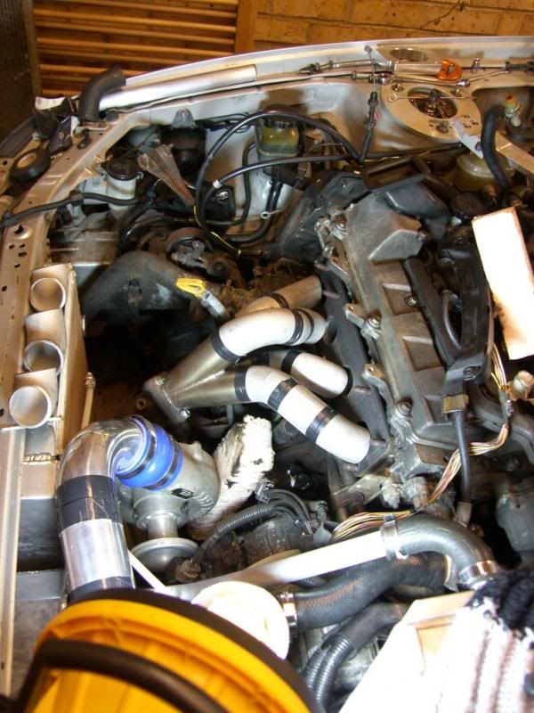
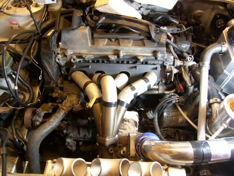
When popped on to the head, it all fits rather well The ports need a little fettling to fit 100%, but overall, good
[img src="http://i27.photobucket.com/albums/c186/twin_charged/Celica/SH105467_zps3abf2aa6.jpg" style="max-width:100%;"]
Just imagine the pipes in between they are in the post!
[img src="http://i27.photobucket.com/albums/c186/twin_charged/Celica/SH105470_zps96e20108.jpg" style="max-width:100%;"]
[img src="http://i27.photobucket.com/albums/c186/twin_charged/Celica/SH105469_zps8170c6bb.jpg" style="max-width:100%;"]
One interesting thing is that the exhaust port for cylinder one is almost 10mm longer that all the others, I did a lot of measuring to make sure this was the case. I think it may have something to do with the port being angled towards the turbo, so a perpendicular cross section will actually be identical to the others?
So next, I need more parts! My 30th is coming up soon, so I might treat myself to some tools and a few bits for the project
Laters,
J
Little update, finished all of the heavy metal work
The exhaust head flange was always going to be difficult, oval ports, many holes and just quite a big bit of steel
I started by marking it all out using the exhaust gasket as a guide, this was checked against the head and although the hole centers are in the right place, the holes are not the right size. This applies particularly to the ports, the gasket holes are +5mm in all dimensions, I guess to ensure clearance under all tolerance conditions. A restriction on one cylinder would be catastrophic under full load conditions, with increased exhaust gas temps and gas flow restrictions causing fueling imbalances and possible piston and head problems.
Anyway, they were marked out -
[img src="http://i27.photobucket.com/albums/c186/twin_charged/Celica/SH105462_zps01d68815.jpg" style="max-width:100%;"]
I don't have any pictures of the drilling, as it was tough going, the drill was untouchably hot by the time the holes were drilled, I was also occupied swatting wasps (got a queen so I am happy
).Post drilling this is where we were -
[img src="http://i27.photobucket.com/albums/c186/twin_charged/Celica/SH105464_zpsb2dae822.jpg" style="max-width:100%;"]
I did start using a dremel but the shards of metal were so sharp that I stopped, pulled the swarf out of my hands and cracked out the hand file
[img src="http://i27.photobucket.com/albums/c186/twin_charged/Celica/SH105465_zpsc8eed2fd.jpg" style="max-width:100%;"]
The half round actually made short work of the material left, I got a good dab on and smashed through it all
I also took the opportunity to slot the holes, not to make it fit but to allow for heat expansion. The mild steel I have used is not as prone as stainless, but it is a good precaution to take at this stage, the last thing I want is snapped studs
[img src="http://i27.photobucket.com/albums/c186/twin_charged/Celica/SH105466_zps3c7041d5.jpg" style="max-width:100%;"]
When popped on to the head, it all fits rather well
The ports need a little fettling to fit 100%, but overall, good [img src="http://i27.photobucket.com/albums/c186/twin_charged/Celica/SH105467_zps3abf2aa6.jpg" style="max-width:100%;"]
Just imagine the pipes in between
they are in the post![img src="http://i27.photobucket.com/albums/c186/twin_charged/Celica/SH105470_zps96e20108.jpg" style="max-width:100%;"]
[img src="http://i27.photobucket.com/albums/c186/twin_charged/Celica/SH105469_zps8170c6bb.jpg" style="max-width:100%;"]
One interesting thing is that the exhaust port for cylinder one is almost 10mm longer that all the others, I did a lot of measuring to make sure this was the case. I think it may have something to do with the port being angled towards the turbo, so a perpendicular cross section will actually be identical to the others?
So next, I need more parts! My 30th is coming up soon, so I might treat myself to some tools and a few bits for the project
Laters,
J
August 31st 2013
Been a busy boy today!
This week I spent my monthly budget on hard boost pipe bends, decided to go for 2.5" from the turbo to charge cooler then 3" from charge cooler to the throttle body. This is mainly so that I don't have to use any reducers, just nice neat hump hoses
I ordered four 180 degree bends, they have nice long tails and cost only a little more than a 90 degree, kinder on the pocket
I ordered the hump hoses, and a lot of clamps, in fact I spent £56 on clamps ops: However they are constant tension worm drive clamps, WRC spec, and I have enough for the entire cooling system, charge cooler water pipes and all the boost pipes

So today after the pipes arrived, I got brave with a hacksaw and the belt linisher
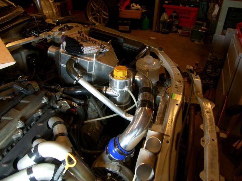
First of all I mocked up the turbo again, the position has changed a little again as once I started looking, putting a 180 degree bend in the boost pipe was unnecessary. Moving it lower meant we could have two 90's to the charge cooler, much better.
Then I started cutting the hard pipes, not easy as you have to visualise the pipe run in 3D before cutting. It is not finished yet, but this is where we ended up -
And with the strut brace in place -
Just need an AC TIG now to weld them all together!
Pretty happy with all this again, it is coming out the same as the picture in my head
J
Been a busy boy today!
This week I spent my monthly budget on hard boost pipe bends, decided to go for 2.5" from the turbo to charge cooler then 3" from charge cooler to the throttle body. This is mainly so that I don't have to use any reducers, just nice neat hump hoses
I ordered four 180 degree bends, they have nice long tails and cost only a little more than a 90 degree, kinder on the pocket
I ordered the hump hoses, and a lot of clamps, in fact I spent £56 on clamps
ops: However they are constant tension worm drive clamps, WRC spec, and I have enough for the entire cooling system, charge cooler water pipes and all the boost pipes So today after the pipes arrived, I got brave with a hacksaw and the belt linisher
First of all I mocked up the turbo again, the position has changed a little again as once I started looking, putting a 180 degree bend in the boost pipe was unnecessary. Moving it lower meant we could have two 90's to the charge cooler, much better.
Then I started cutting the hard pipes, not easy as you have to visualise the pipe run in 3D before cutting. It is not finished yet, but this is where we ended up -
And with the strut brace in place -
Just need an AC TIG now to weld them all together!
Pretty happy with all this again, it is coming out the same as the picture in my head
J
September 3rd 2013
Just a small update, got a cold so not feeling too enthusiastic.
Started putting up new lights in the garage, I have been working with a single energy saving bulb in a desk lamp so far, and we will soon have four full length strip lights
I also decided to have a quick bash at a beading tool, I only need a few doing so I don't want to pay a fabricator to do it. I took an old pair of mole grips and filed a semi circular groove in one jaw -
I then took a bolt, filed a flat on it -
Then zapped it into the other moley jaw -
I tried by hand but it did not have enough leverage, so I then put it into the vice and had another go, the result is pretty good! Could be even better with practice I think Here is a pic compared to the bead that arrived on the pipes I bought -
I need to get the AC TIG sorted to I can finish the damn boost pipes
J
Just a small update, got a cold so not feeling too enthusiastic.
Started putting up new lights in the garage, I have been working with a single energy saving bulb in a desk lamp so far, and we will soon have four full length strip lights
I also decided to have a quick bash at a beading tool, I only need a few doing so I don't want to pay a fabricator to do it. I took an old pair of mole grips and filed a semi circular groove in one jaw -
I then took a bolt, filed a flat on it -
Then zapped it into the other moley jaw -
I tried by hand but it did not have enough leverage, so I then put it into the vice and had another go, the result is pretty good! Could be even better with practice I think
Here is a pic compared to the bead that arrived on the pipes I bought - I need to get the AC TIG sorted to I can finish the damn boost pipes
J
September 14th 2013
Little update, things have arrived from america, my fuel rail and collector. Also a package from poland with my charge cooler tank
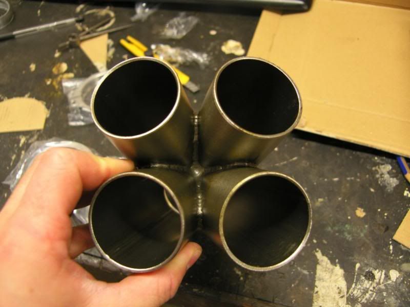
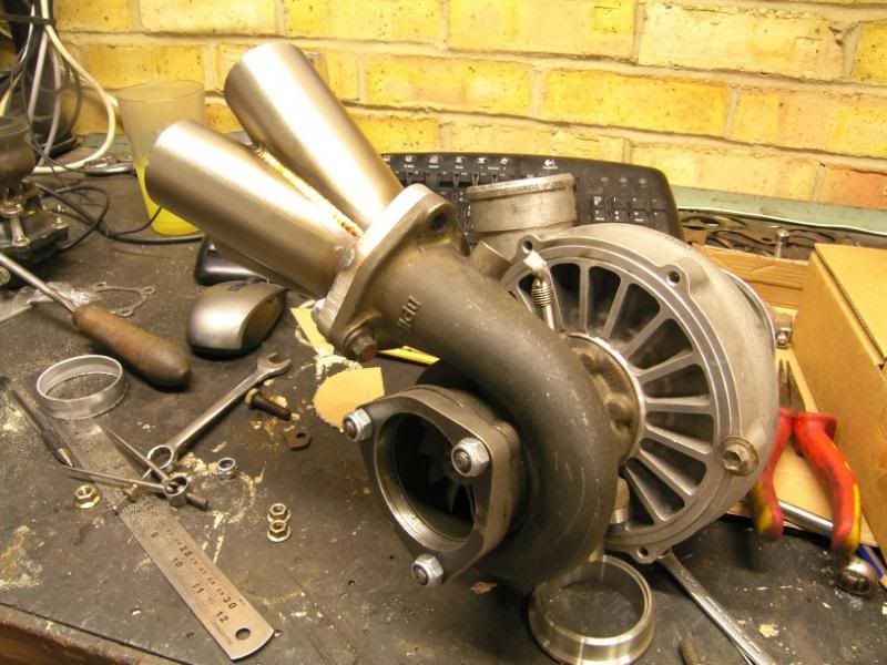
Here is the collector -
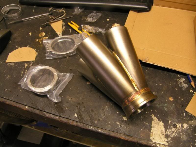
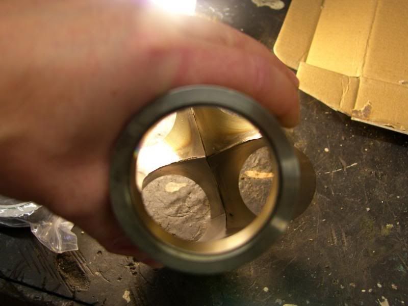
Really nicely put together, penetration is not great on the welds, but that can be sorted using my TIG. I will also run beads on the inside, as there is no penetration at all here -
Outside the welds are lovely though
So what to do next? Take a hacksaw to it :lol:
As it arrived, the mounting was a Tial V-Band type, it came with a flange too but this is not a lot of use as I have more than one exhaust housing. So I cut off the collector flange which will be used on the wastegate, and I will be welding on the flange I made earlier.
I took the opportunity to tack it onto the flange -
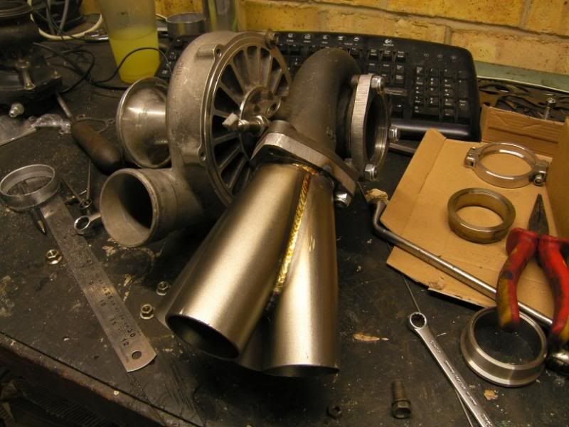
And then size it up on the engine -
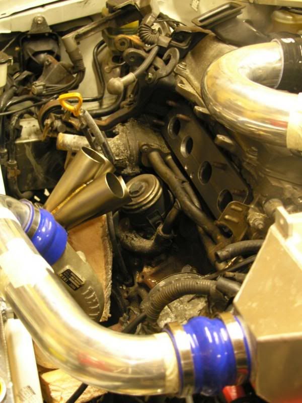
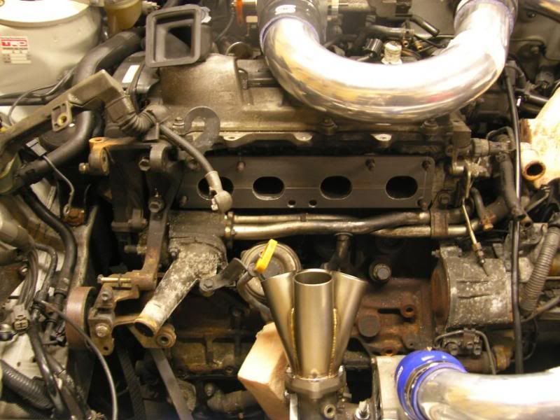
I have mounted it 90 degrees out to how they normally are, so that I can get the 1-3-4-2 order on the primaries a little easier. I am also quite short on space for fasteners, so either studs will be used or I will come up with some other cunning plan
I will get some shots of the fuel rail and swirl pot tomorrow
J
Little update, things have arrived from america, my fuel rail and collector. Also a package from poland with my charge cooler tank
Here is the collector -
Really nicely put together, penetration is not great on the welds, but that can be sorted using my TIG. I will also run beads on the inside, as there is no penetration at all here -
Outside the welds are lovely though
So what to do next? Take a hacksaw to it :lol:
As it arrived, the mounting was a Tial V-Band type, it came with a flange too but this is not a lot of use as I have more than one exhaust housing. So I cut off the collector flange which will be used on the wastegate, and I will be welding on the flange I made earlier.
I took the opportunity to tack it onto the flange -
And then size it up on the engine -
I have mounted it 90 degrees out to how they normally are, so that I can get the 1-3-4-2 order on the primaries a little easier. I am also quite short on space for fasteners, so either studs will be used or I will come up with some other cunning plan
I will get some shots of the fuel rail and swirl pot tomorrow
J
September 15th 2013
Had a good day between watching the streamed goodwood revival races live and time spent in the garage. Plenty of progress
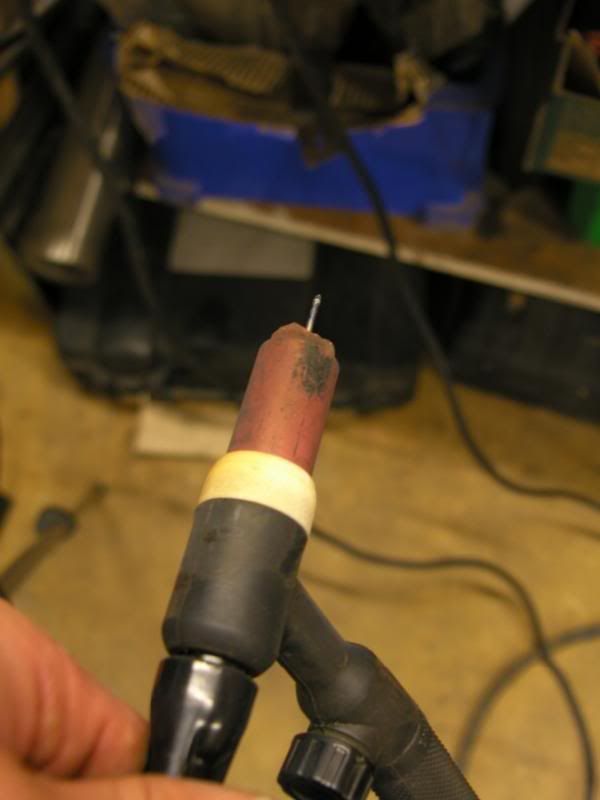
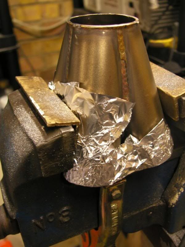
Yesterday I showed you the lack of penetration on the collector imported from america, I do not have a long reach torch so had to get brave with the tungsten
Collector as we started -
I blocked up the bottom of the pipes using tin foil so that the argon would pool, making my life a little easier as the ceramic cup would not be doing its job at the kind of projection length needed.
Tungsten poking out a LONG way! (yes I know the ceramic is screwed, there is a new one on it's way, this one got very hot a few days ago )
All foiled up -
Welding it was not fun, even with all the preparation the arc was still wandering around all over the place. Fortunately the edges of the stainless were heating up much faster than the surroundings, so I could keep the weld pool moving. The results were actually very good, I managed to get all the edges sorted out without losing the sharp spire in the center -
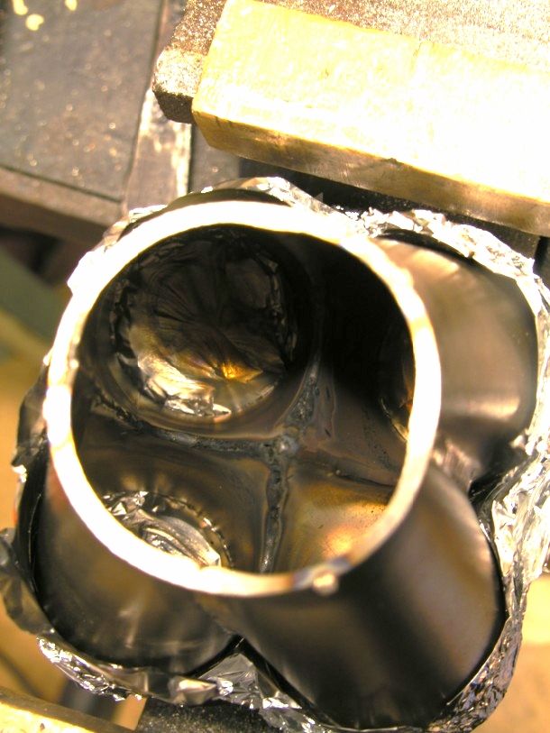
Next up the flange needed some attention, the four pipes of the collector came together into a four leaf clover shape, this needed to be copied and filed into the flange. I lined it up and gave it a quick squirt of paint to stencil on the shape -
This was then hand filed to shape, yes it was tough :lol:
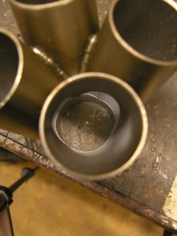
Looking down the collector, it was much closer and ready to be seam welded on the inside -
I then put three stitch welds on the outside, between the bolt holes. This was mainly for clearance as everything is quite tight round them!
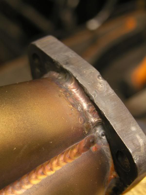
Lovely
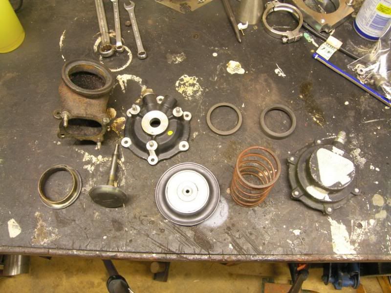
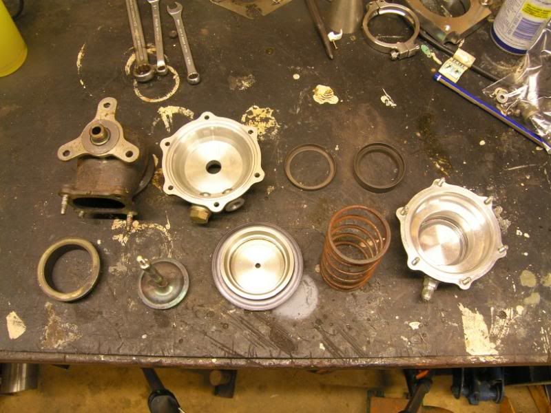
As a reward I decided to dismantle one of my wastegates, see what they were like inside both construction and condition wise. The construction is really excellent, just little things like steel spring cups so that they spring does not eat into the aluminium housings. And a proper bronze valve guide for the valve shaft. Even the diaphragm is a thicker different material to usual?
I will be machining off the current unknown dimension V-band flange and welding on one of my ones.
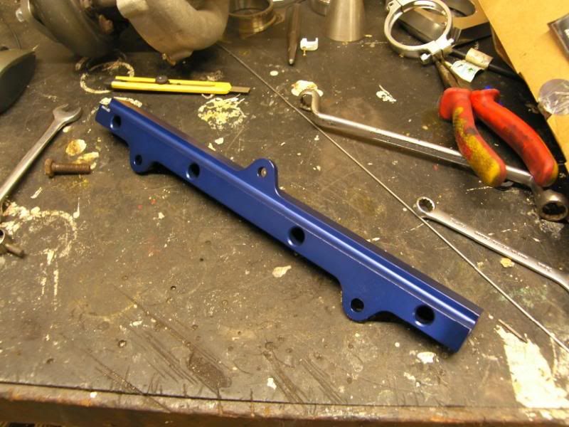
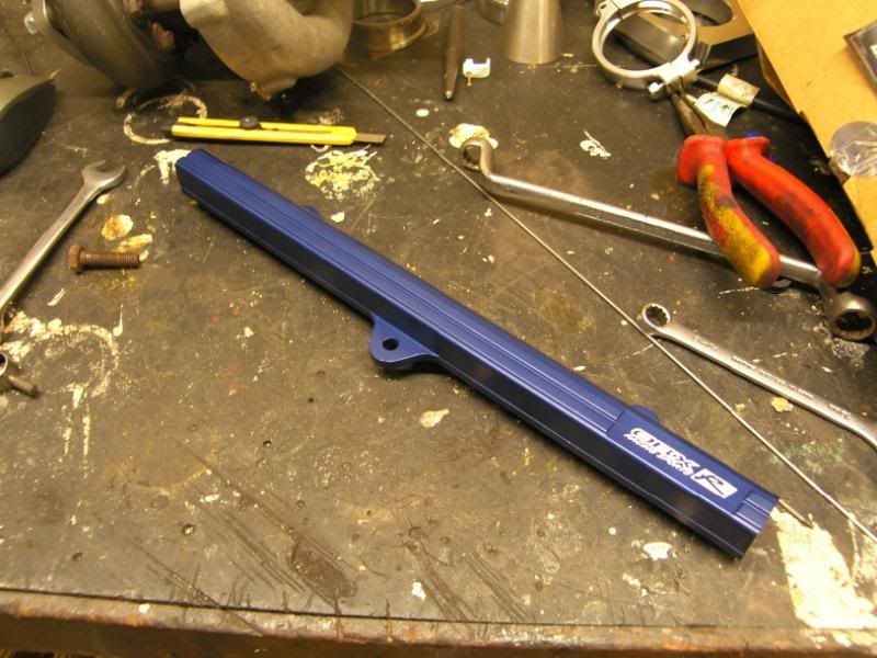
Finally, I also unpacked the fuel rail (just for you diablou!), lovely construction again, just a few sharp edges that had to be taken off
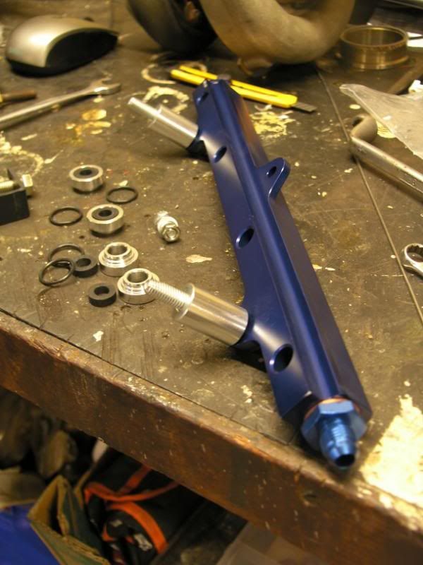
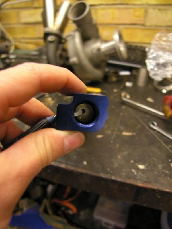
De-burring tool -
Thats it folks, more soon
J
Had a good day between watching the streamed goodwood revival races live and time spent in the garage. Plenty of progress
Yesterday I showed you the lack of penetration on the collector imported from america, I do not have a long reach torch so had to get brave with the tungsten
Collector as we started -
I blocked up the bottom of the pipes using tin foil so that the argon would pool, making my life a little easier as the ceramic cup would not be doing its job at the kind of projection length needed.
Tungsten poking out a LONG way! (yes I know the ceramic is screwed, there is a new one on it's way, this one got very hot a few days ago
)All foiled up -
Welding it was not fun, even with all the preparation the arc was still wandering around all over the place. Fortunately the edges of the stainless were heating up much faster than the surroundings, so I could keep the weld pool moving. The results were actually very good, I managed to get all the edges sorted out without losing the sharp spire in the center -
Next up the flange needed some attention, the four pipes of the collector came together into a four leaf clover shape, this needed to be copied and filed into the flange. I lined it up and gave it a quick squirt of paint to stencil on the shape -
This was then hand filed to shape, yes it was tough :lol:
Looking down the collector, it was much closer and ready to be seam welded on the inside -
I then put three stitch welds on the outside, between the bolt holes. This was mainly for clearance as everything is quite tight round them!
Lovely
As a reward I decided to dismantle one of my wastegates, see what they were like inside both construction and condition wise. The construction is really excellent, just little things like steel spring cups so that they spring does not eat into the aluminium housings. And a proper bronze valve guide for the valve shaft. Even the diaphragm is a thicker different material to usual?
I will be machining off the current unknown dimension V-band flange and welding on one of my ones.
Finally, I also unpacked the fuel rail (just for you diablou!), lovely construction again, just a few sharp edges that had to be taken off
De-burring tool -
Thats it folks, more soon
J
December 15th 2013
Finally a bit of an update!
Things have been a bit busy in the Hill household, busy with work, our little pickle Ruby and working on the house too. All this meant that the Celica took a bit of a back seat for a while, I have now got a bit of my car mojo back and found some time to be able to work on it again
I did a little work on the chargecooler mounts, with the packaging constraints the mounts were proving a little difficult to site, I manage to fabricated a mount that uses two of the original thread locations to hold one of the most inaccessible points on the core, solving another issue.
Marked out on 5mm aluminium plate -
Cut out by and shaped by hand, then the necessary bends put in to locate it securely without putting any stress on the chargecooler core –
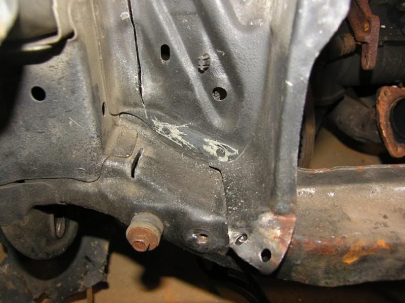
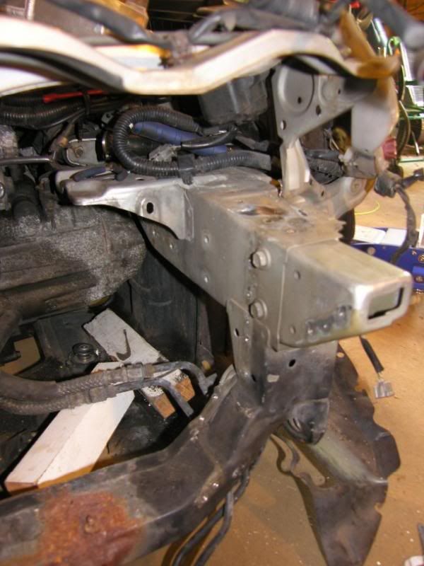
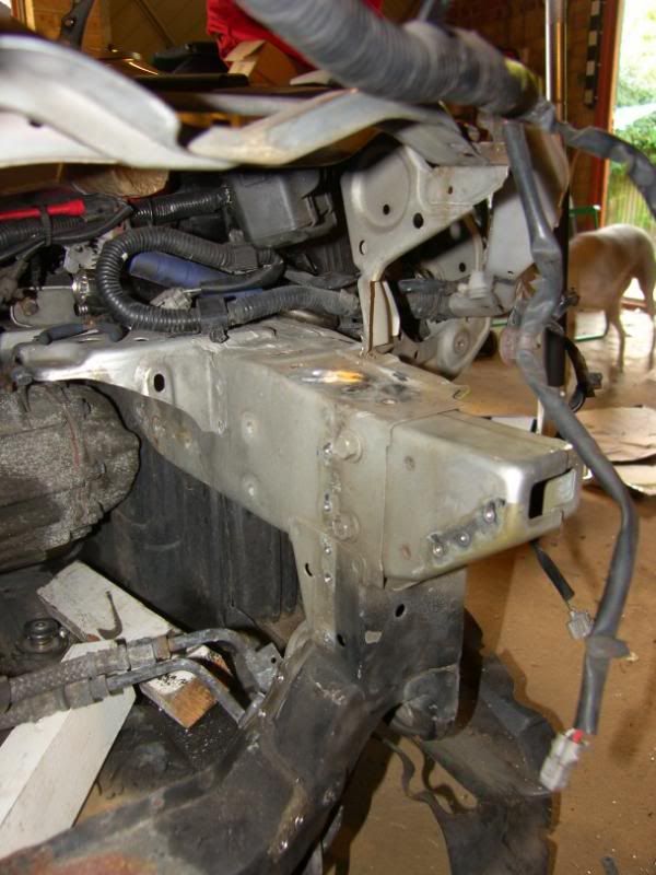
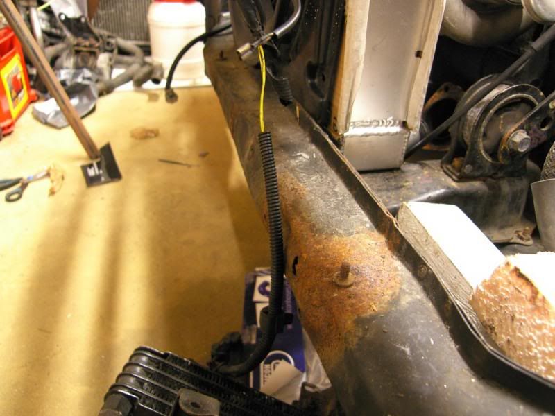
Next up I wanted to update the front of the chassis to allow the cooling package to fit and also to remove the lower front bar. The car has had a small impact at some point and the bar was not in great shape, I could repair it but it is heavy and not a very rigid design. With the location of the radiator the bar location actually became redundant, the only purpose of this bar was to maintain the separation of the front chassis rails and for the longitudinal engine mounting bar, both could be replaced with a more elegant solution.
This is the lower bar, showing the poor condition –
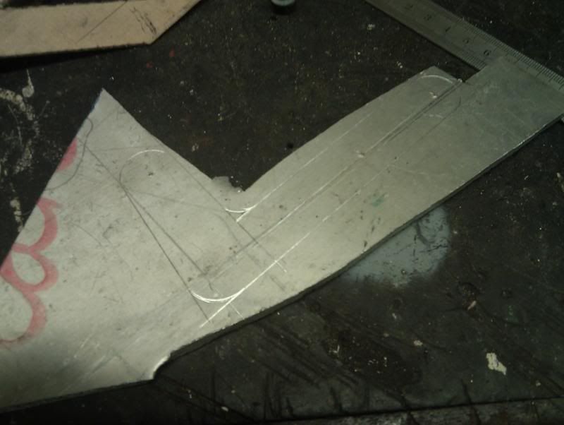
I started by locating some suitable factory bolt points and then making a template –
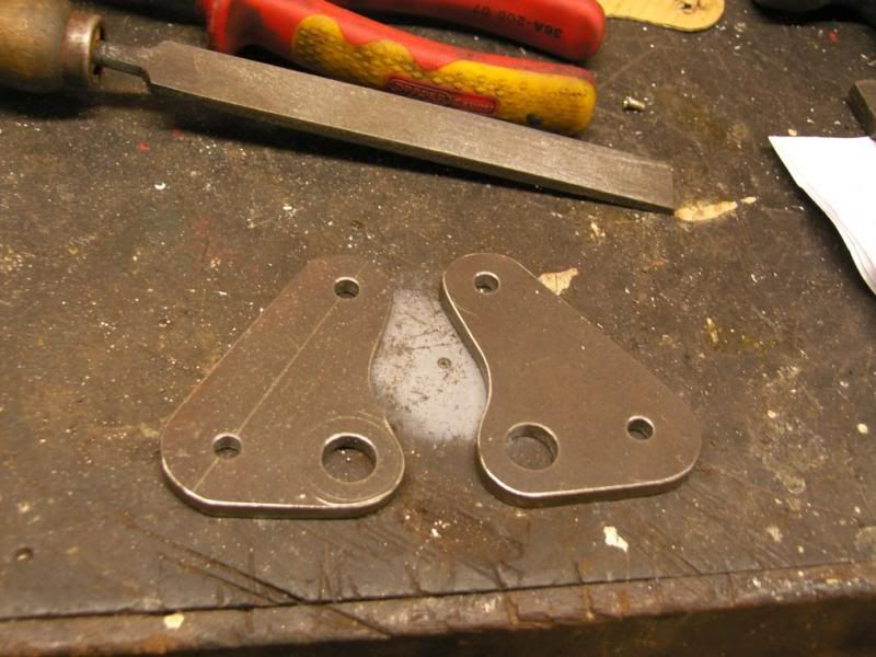
Marked out and started the slow hand fabrication process –
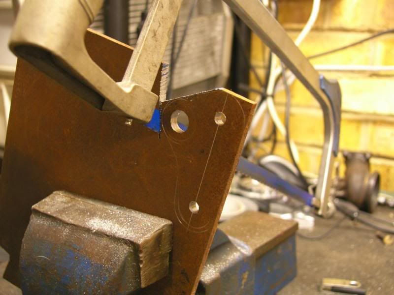
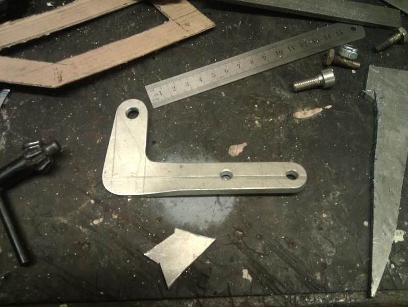
Two identical plates ready for fitting to the chassis –
Tested for fitment –
A bar was then cut to size and fettled to fit –
Once I was happy I got the TIG out and stuck it all together –
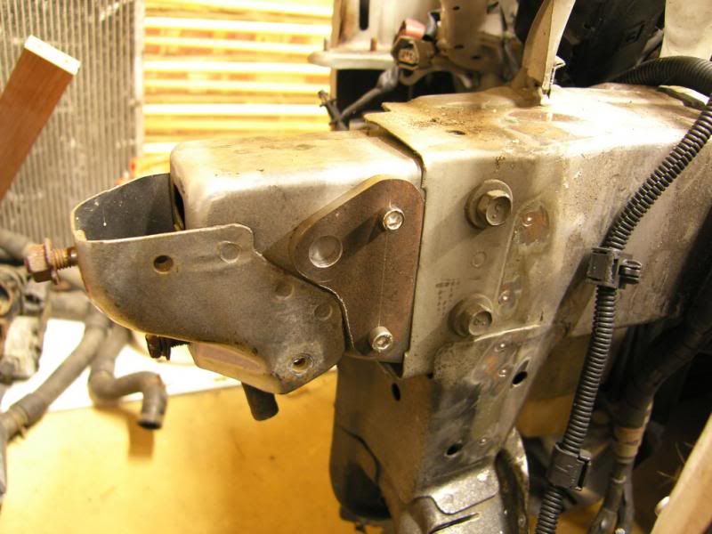
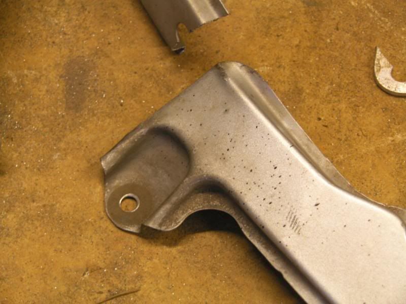
This bar will be the mounting point for various items including the radiators and lights, the original light mountings will be used for the outer lights and they had to be trimmed to be fit.
Here is a standard mounting, and the modified one with the section that has been cut off –
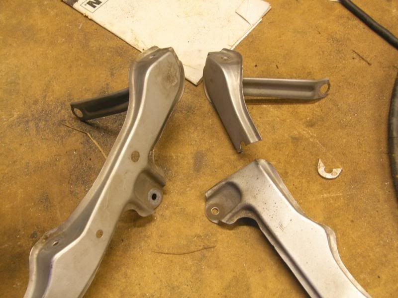
I tried to get the modified mount to look as factory as possible –
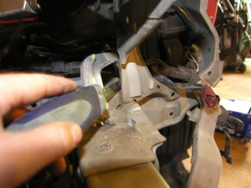
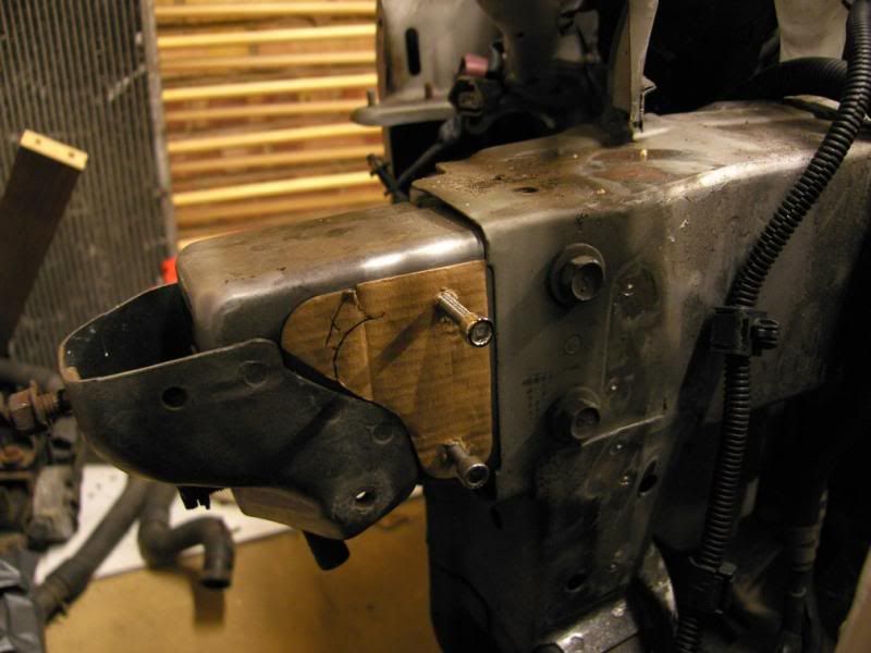
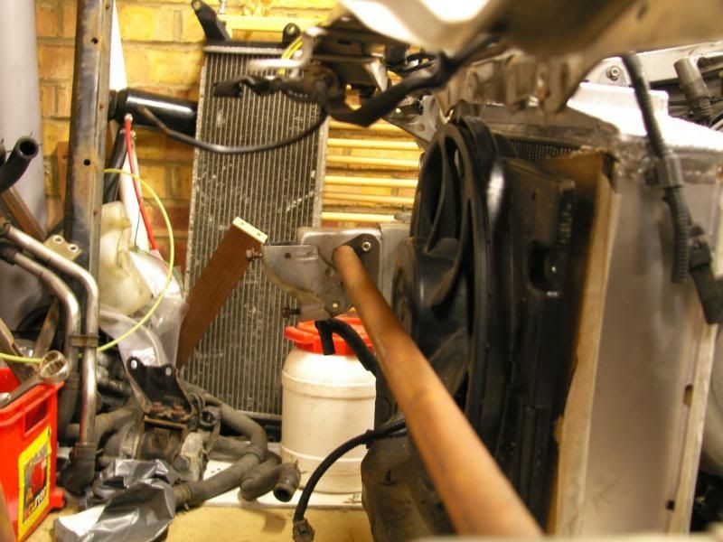
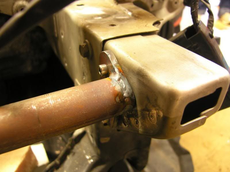
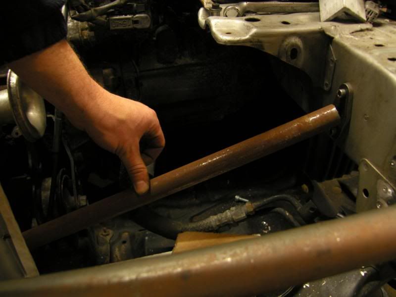
Finally I started the front engine mounting system, this will be a spaceframe design, triangulated to ensure the necessary rigidity. The first mount will be using these two factory M6 mounting points on the chassis rail –
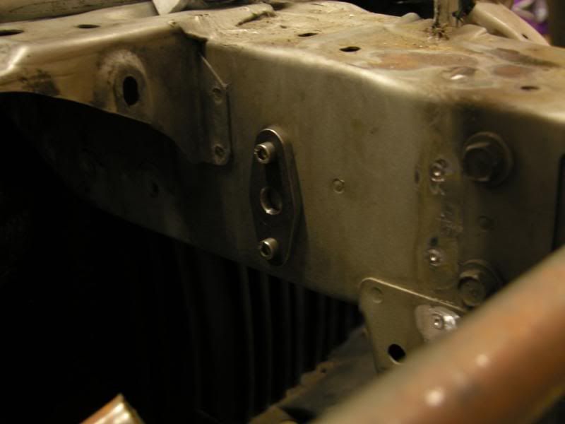
With the tube held in place to give an idea of the location –
That was all for today, but progress should be steady over the next few weeks, orders will be placed for the remaining exhaust manifold parts and down pipe parts.
I am thinking of putting the wastegate pipe out of the bonnet vent, not sure if this is a good idea, but it is not a daily driver so should be bearable
Thanks chaps,
J
Finally a bit of an update!
Things have been a bit busy in the Hill household, busy with work, our little pickle Ruby and working on the house too. All this meant that the Celica took a bit of a back seat for a while, I have now got a bit of my car mojo back and found some time to be able to work on it again
I did a little work on the chargecooler mounts, with the packaging constraints the mounts were proving a little difficult to site, I manage to fabricated a mount that uses two of the original thread locations to hold one of the most inaccessible points on the core, solving another issue.
Marked out on 5mm aluminium plate -
Cut out by and shaped by hand, then the necessary bends put in to locate it securely without putting any stress on the chargecooler core –
Next up I wanted to update the front of the chassis to allow the cooling package to fit and also to remove the lower front bar. The car has had a small impact at some point and the bar was not in great shape, I could repair it but it is heavy and not a very rigid design. With the location of the radiator the bar location actually became redundant, the only purpose of this bar was to maintain the separation of the front chassis rails and for the longitudinal engine mounting bar, both could be replaced with a more elegant solution.
This is the lower bar, showing the poor condition –
I started by locating some suitable factory bolt points and then making a template –
Marked out and started the slow hand fabrication process –
Two identical plates ready for fitting to the chassis –
Tested for fitment –
A bar was then cut to size and fettled to fit –
Once I was happy I got the TIG out and stuck it all together –
This bar will be the mounting point for various items including the radiators and lights, the original light mountings will be used for the outer lights and they had to be trimmed to be fit.
Here is a standard mounting, and the modified one with the section that has been cut off –
I tried to get the modified mount to look as factory as possible –
Finally I started the front engine mounting system, this will be a spaceframe design, triangulated to ensure the necessary rigidity. The first mount will be using these two factory M6 mounting points on the chassis rail –
With the tube held in place to give an idea of the location –
That was all for today, but progress should be steady over the next few weeks, orders will be placed for the remaining exhaust manifold parts and down pipe parts.
I am thinking of putting the wastegate pipe out of the bonnet vent, not sure if this is a good idea, but it is not a daily driver so should be bearable
Thanks chaps,
J
December 17th 2013
Little update for today, I had a bit of a brain wave whilst at my desk at work. Now the brain wave did not work out but I have come to another solution.
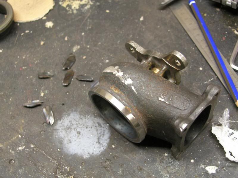
I have five ex-IMSA wastegates , they are stunning quality with all fixings by stud and nut, bronze valve guide and thin wall cast steel body.
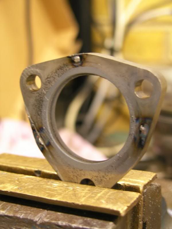
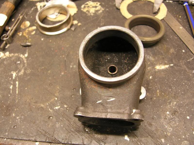
I have wanted to use one on this project for a long time, but the issue with doing so is the inlet join. When fitted originally it was sealed together with a v-band type connector, I do not have the mating half of this connector, not a massive issue as I could machine something suitable. The main issue is that I am also missing the band clamp, something I cannot fabricate and despite looking high and low, I cannot find a suitable item to use.
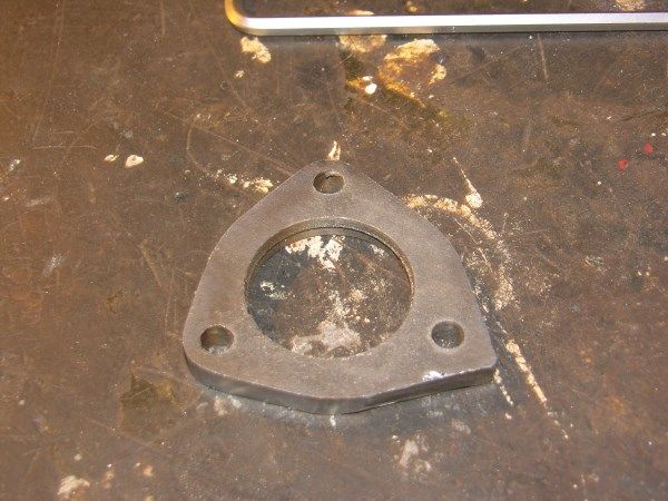
Here is the wastegate flange -
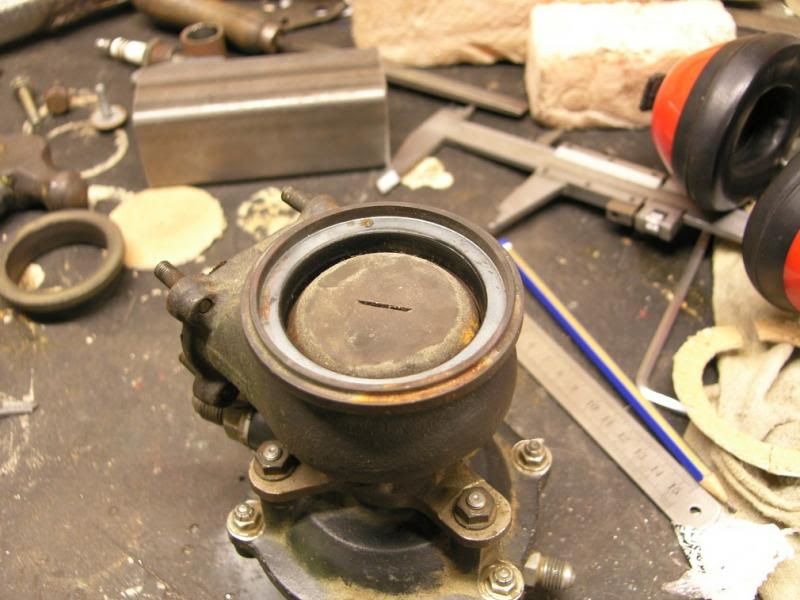
My initial idea was to tap the flange to take a number of fixings and then mate a flange to it, the issue with this was the lack of flange width to tap.
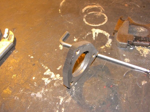
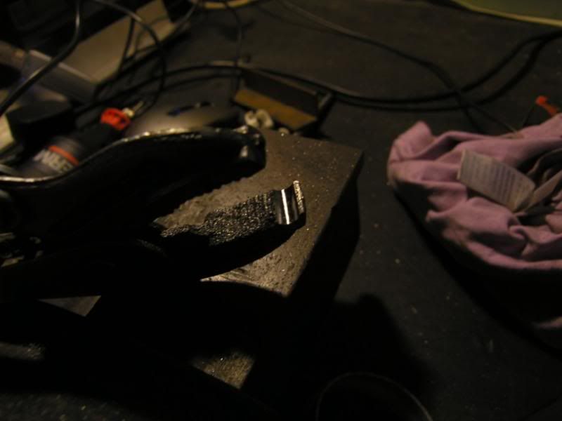
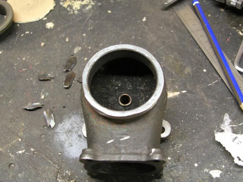
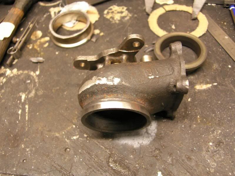
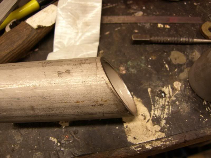
So, finally, I decided to sacrifice one of the wastegates to the god of speed, and start cutting it up
The body is made from a very hard steel alloy of some sort, it took the edge off a hacksaw blade, and there was too much material to just linish off. So the angle grinder and 1mm slitting disc was broken out, this made short work of the flange giving me a much better point to linish back from.
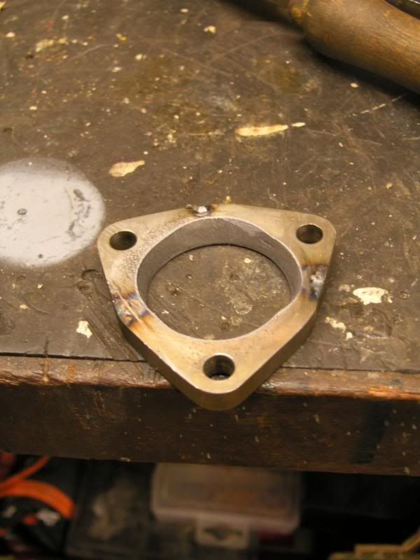
Bits sliced off the wastegate body –
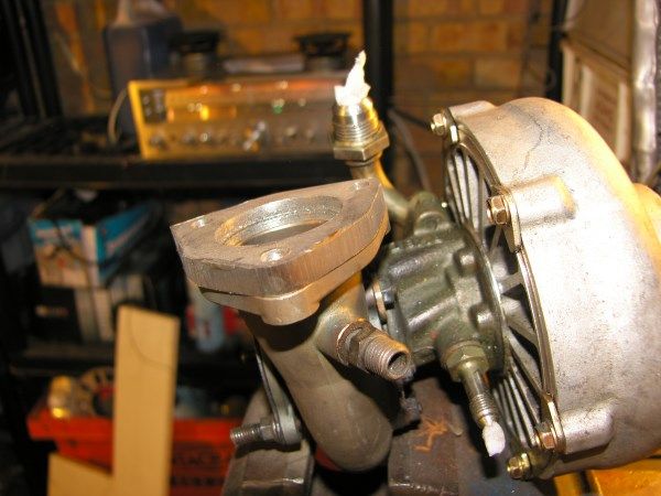
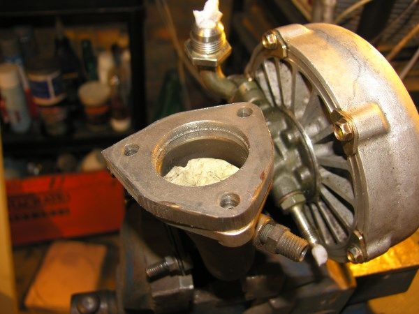
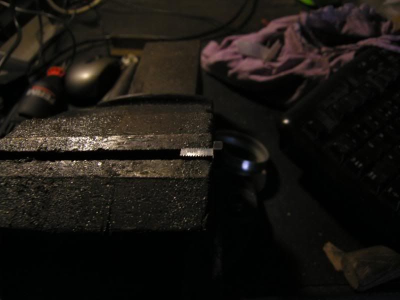
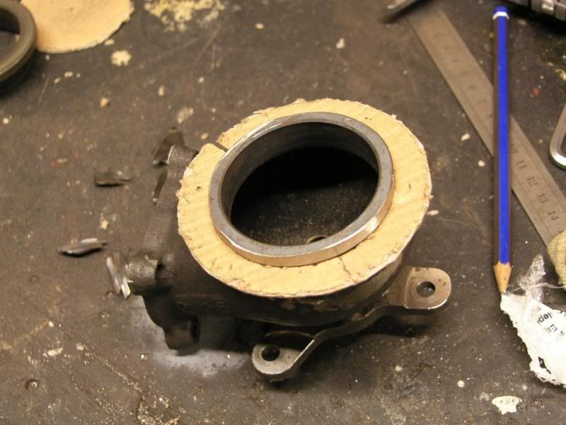
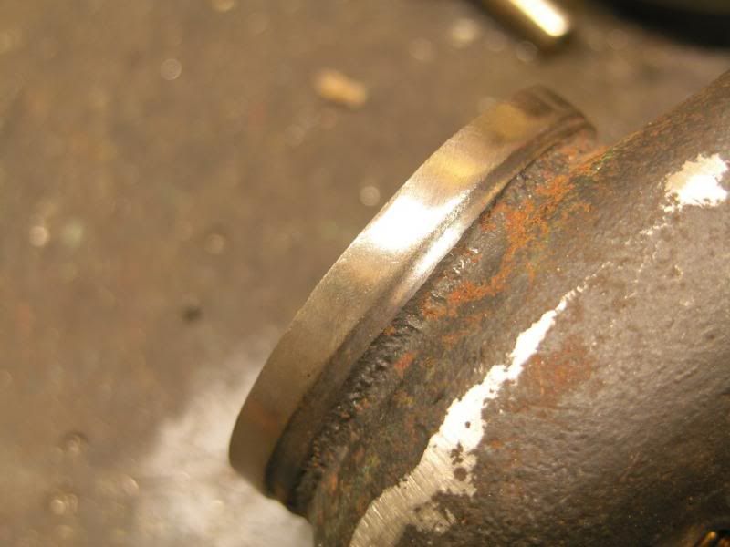
Linished back close to where I want it to be –
I will make up a flange that will be level with the current surface, allowing the floating seat to seal properly -
I might have a go at making some flanges tomorrow
J
Little update for today, I had a bit of a brain wave whilst at my desk at work. Now the brain wave did not work out but I have come to another solution.
I have five ex-IMSA wastegates , they are stunning quality with all fixings by stud and nut, bronze valve guide and thin wall cast steel body.
I have wanted to use one on this project for a long time, but the issue with doing so is the inlet join. When fitted originally it was sealed together with a v-band type connector, I do not have the mating half of this connector, not a massive issue as I could machine something suitable. The main issue is that I am also missing the band clamp, something I cannot fabricate and despite looking high and low, I cannot find a suitable item to use.
Here is the wastegate flange -
My initial idea was to tap the flange to take a number of fixings and then mate a flange to it, the issue with this was the lack of flange width to tap.
So, finally, I decided to sacrifice one of the wastegates to the god of speed, and start cutting it up
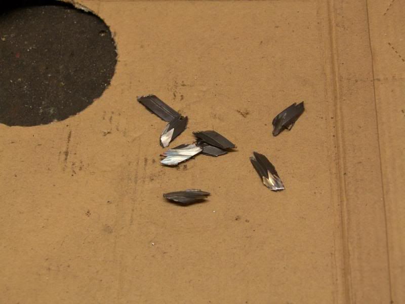
The body is made from a very hard steel alloy of some sort, it took the edge off a hacksaw blade, and there was too much material to just linish off. So the angle grinder and 1mm slitting disc was broken out, this made short work of the flange giving me a much better point to linish back from.
Bits sliced off the wastegate body –
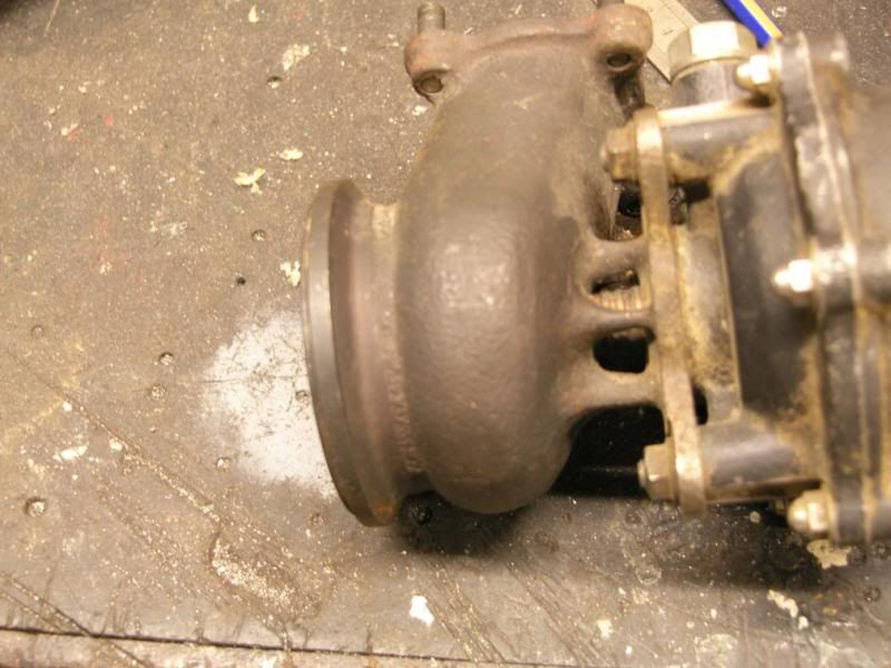
Linished back close to where I want it to be –
I will make up a flange that will be level with the current surface, allowing the floating seat to seal properly -
I might have a go at making some flanges tomorrow
J
December 18th 2013
Small update
After cutting off the wastegate flange yesterday, I was left with a neat but uneven face that I want to weld a ring on to. I do not have access to a lathe to true this face up, so I had to get creative
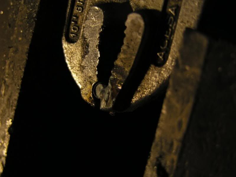
I clamped the wastegate body into the pillar drill using the valve stem as the central point, the body was prevented from turning with ...... gaffer tape, lol!
I then got a carbide bit in the dremel and braced it against the drill table, then slowly brought it into contact with the body -
(click on the below to watch a video)
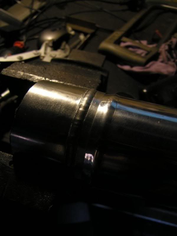
After this the surface finish was good and the OD nice and true
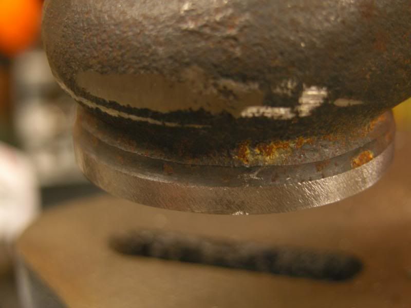
I then put a small drum sanding bit in the dremel to further tidy the surface
Now all I need
Small update
After cutting off the wastegate flange yesterday, I was left with a neat but uneven face that I want to weld a ring on to. I do not have access to a lathe to true this face up, so I had to get creative
I clamped the wastegate body into the pillar drill using the valve stem as the central point, the body was prevented from turning with ...... gaffer tape, lol!
I then got a carbide bit in the dremel and braced it against the drill table, then slowly brought it into contact with the body -
(click on the below to watch a video)
After this the surface finish was good and the OD nice and true
I then put a small drum sanding bit in the dremel to further tidy the surface
Now all I need
January 4th 2014
Little update, we have had a excellent christmas and new year break, and my lovely wife even put pressure on me to spend more time in the garage
It does not look like much has happened, but I have spent time finalising positions for pipe work and tanks. The charge cooler swirl pot location has changed and is now lower than the top of the core, so a small header tank will need to be installed, not a big problem. The plus side is much neater routing of the pipe work and what should be a more effective system, with the swirl pot providing a good head of coolant right above the pump.
The tank is now located in the front wing recess where the airbox usually is, you can also see the pump directly below it -
I whipped up the last bracket for the chargecooler core, a small tab was TIG'ed on to the chassis / engine mount, this provided a bolting point to triangulate the core. A small bar was then marked out and drilled to join the two parts -
Unfortunately my belt sander has died, so there was plenty of this to shape the plate -
I have also tried bending some aluminium pipe at home using a bending spring and some brute force I have found the limit for 1.6mm wall 25mm dia pipe to be around 100 degree bend at 2xD, then it work hardens/thins to the point where it snaps and I fall on my Still managed to get a tidy pipe bent up for the core to rad pipe.
This is where we stopped for the day -
Not looking too bad Did a few other little bits and bobs, trimmed some of the constant tensions clamps to length (I hate excess length, cuts hands to ribbons!) popped a few other now surplus brackets off, and took the coil off the firewall as we are going to COP's.
I am still waiting on the stainless steel delivery, I am hoping for next week. I have also had a quote for a nice fabricated swirl pot for the engine cooling system, this will be 100mm diameter and 177mm tall, plenty of volume and will locate perfectly just in front of the charge cooler core.
Hope you are all well.
J
Little update, we have had a excellent christmas and new year break, and my lovely wife even put pressure on me to spend more time in the garage
It does not look like much has happened, but I have spent time finalising positions for pipe work and tanks. The charge cooler swirl pot location has changed and is now lower than the top of the core, so a small header tank will need to be installed, not a big problem. The plus side is much neater routing of the pipe work and what should be a more effective system, with the swirl pot providing a good head of coolant right above the pump.
The tank is now located in the front wing recess where the airbox usually is, you can also see the pump directly below it -
I whipped up the last bracket for the chargecooler core, a small tab was TIG'ed on to the chassis / engine mount, this provided a bolting point to triangulate the core. A small bar was then marked out and drilled to join the two parts -
Unfortunately my belt sander has died, so there was plenty of this to shape the plate -
I have also tried bending some aluminium pipe at home using a bending spring and some brute force
I have found the limit for 1.6mm wall 25mm dia pipe to be around 100 degree bend at 2xD, then it work hardens/thins to the point where it snaps and I fall on my Still managed to get a tidy pipe bent up for the core to rad pipe.This is where we stopped for the day -
Not looking too bad
Did a few other little bits and bobs, trimmed some of the constant tensions clamps to length (I hate excess length, cuts hands to ribbons!) popped a few other now surplus brackets off, and took the coil off the firewall as we are going to COP's.I am still waiting on the stainless steel delivery, I am hoping for next week. I have also had a quote for a nice fabricated swirl pot for the engine cooling system, this will be 100mm diameter and 177mm tall, plenty of volume and will locate perfectly just in front of the charge cooler core.
Hope you are all well.
J
January 10th 2014
Finally! After a little mix up at the stainless suppliers, the manifold and down pipe materials have arrived
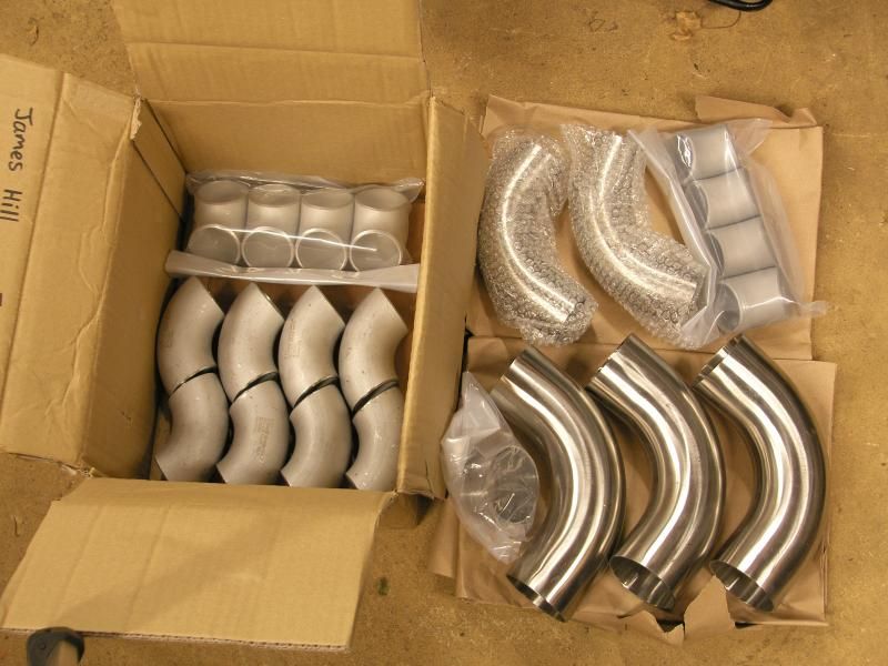
4 x 1.5" I.D. Sch10s 304L short 90 degree bends.
4 x 1.5" I.D. Sch10s 304L 45 degree bends.
8 x 1.5" I.D. Sch10s 304L 90 degree bends.
3 x 2.5" 316L 16G 90 degree bends.
2 x 2" 316L 16G 90 degree bends.
1 x 2.5" - 2" 316L 16G reducer.
Better get that belt sander I was on about
J
Finally! After a little mix up at the stainless suppliers, the manifold and down pipe materials have arrived
4 x 1.5" I.D. Sch10s 304L short 90 degree bends.
4 x 1.5" I.D. Sch10s 304L 45 degree bends.
8 x 1.5" I.D. Sch10s 304L 90 degree bends.
3 x 2.5" 316L 16G 90 degree bends.
2 x 2" 316L 16G 90 degree bends.
1 x 2.5" - 2" 316L 16G reducer.
Better get that belt sander I was on about
J
January 19th 2014
Little update, slowly but surely!
First of all, my custom swirl pot and header tank for the cooling system has arrived I sized it quite large so that I can have my calculated air spring above the water inlet level, this should allow expansion in the system without boiling the water
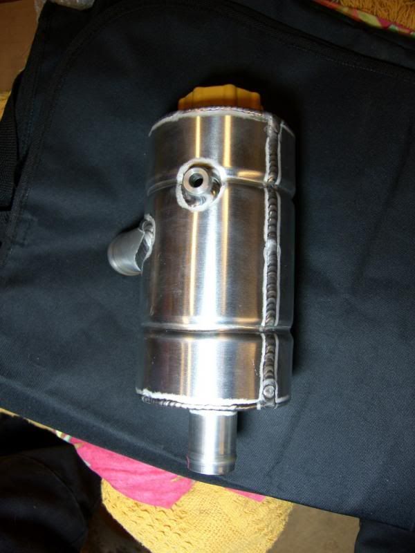
It is 4" round and 7" deep, this equates to just under 1.4 liters in capacity, 1.25" inlet and outlet and a Ford type radiator cap.
I purchased it from here -
http://www.evalution-designs.co.uk/
Chris the owner / fabricator is very helpful and built mine to my specifications, with minimal direction. The result is very tidy
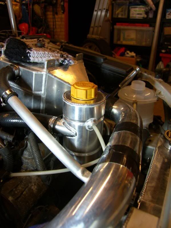
Here is is in location, just in front of the charge cooler -
I have also started on the manifold, cutting various pipes and straights to move towards a snakey solution
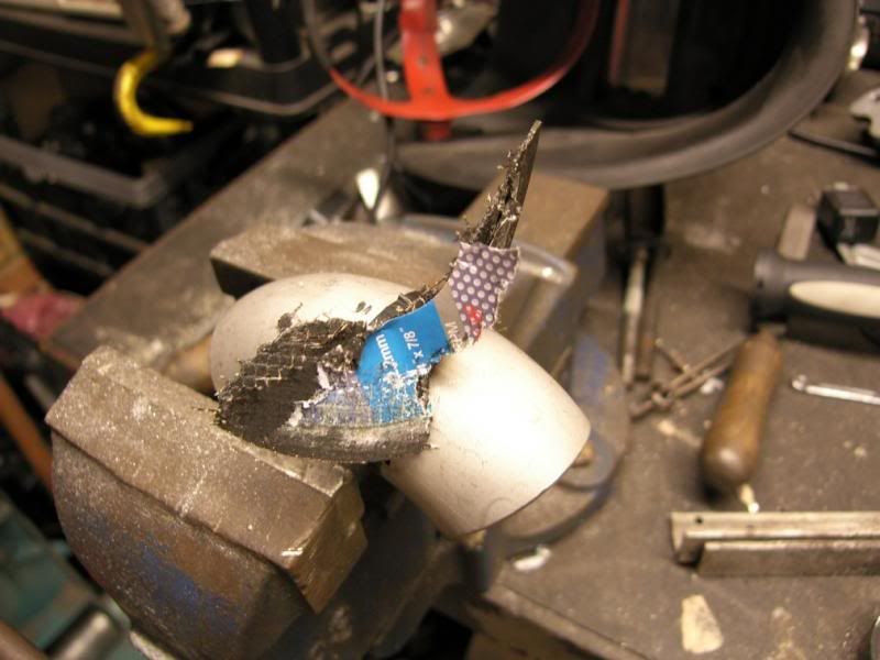
Using a 1.2mm slitting disc I could cut the 3mm wall stainless with ease. Number one cylinder port is at an angle as it comes out of the head, so will require a similar angle from the manifold, it looks wrong but is actually right!
I also found that the mandrel bends have quite a lot of internal stresses still in the material, as I was joining two cuts up, the pipe grabbed the disc and shattered it!
This is where we finished the day, getting there, some fine adjustment required with the belt / disc sander.
So this week I will be fettling the joins and thinking about tacking the parts together
J
Little update, slowly but surely!
First of all, my custom swirl pot and header tank for the cooling system has arrived
I sized it quite large so that I can have my calculated air spring above the water inlet level, this should allow expansion in the system without boiling the water It is 4" round and 7" deep, this equates to just under 1.4 liters in capacity, 1.25" inlet and outlet and a Ford type radiator cap.
I purchased it from here -
http://www.evalution-designs.co.uk/
Chris the owner / fabricator is very helpful and built mine to my specifications, with minimal direction. The result is very tidy
Here is is in location, just in front of the charge cooler -
I have also started on the manifold, cutting various pipes and straights to move towards a snakey solution
Using a 1.2mm slitting disc I could cut the 3mm wall stainless with ease. Number one cylinder port is at an angle as it comes out of the head, so will require a similar angle from the manifold, it looks wrong but is actually right!
I also found that the mandrel bends have quite a lot of internal stresses still in the material, as I was joining two cuts up, the pipe grabbed the disc and shattered it!
This is where we finished the day, getting there, some fine adjustment required with the belt / disc sander.
So this week I will be fettling the joins and thinking about tacking the parts together
J
Thanks Krikkit, the casual use of TIG results from having only a TIG to glue metal together. I am sure if I had a MIG, I would use that more!
I have been through a few jobs since I left university years ago, I now have my own business offering specialist calibration services to large automotive manufacturers.
This means lots of time spent at a computer, so the chance to come home and get my hands dirty brings a great deal of happiness and pleasure to my life!
Dave, thank you! The Celica was initially chosen on engineering merit, after years of di*king about with Hillman Imps and repeatedly reaching the next weakest link in the chain, a big shift was on the cards.
I was looking for something within budget, new enough to have things like injection, old enough to not have 10 ECU's, and most importantly have the chassis and drivetrain that can accept all I want to throw at it.
The Celica came up trumps, gearbox and 'diffs capable of absorbing 600hp reliably, forged four / two pot calipers and 315mm discs, and a jolly clever suspension system.
Also, there are so many little details on them too, the two bulges / vents on the bonnet, there to cool the remote reservoir dampers on the WRC cars, a vent to cool the cam belt, radiators for -
Engine coolant
Engine oil
Gearbox oil
Power steering
Charge cooler
And a bit of proper championship pedigree behind the monocoque too
J
Hi,
A friend of mine pointed out this thread to me as i used to own this car around 4/5 years ago, the second owner after it was imported. i also knew the 1st owner of the car as well.
its really good to see how much you have done and that its being given a second chance.
it was always a great car to drive and never let me down.
are you going to be taking it to any shows this year? would like to see it again.
Regards,
Chris

Gassing Station | Readers' Cars | Top of Page | What's New | My Stuff